
 My Inquiry
 My Account


Analog Devices Inc./Maxim Integrated DS21Q554BN+
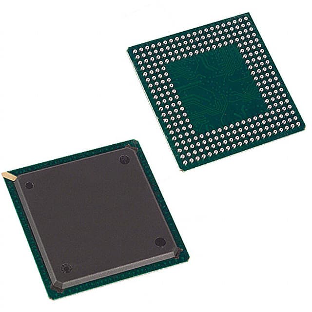
- Part No.:
- DS21Q554BN+
- Manufacturer:
- Analog Devices Inc./Maxim Integrated
- Category:
- Telecom
- Package:
- 256-BGA
- Datasheet:
-
 DS21Q554BN+.pdf
- Description:
- IC TELECOM INTERFACE 256BGA
- Quantity:
- Payment:

- Shipping:

Inventory:160
Please send an inquiry. Send us your inquiry, and we will respond immediately.
Product details
Overview
DS21Q554BN+ from Maxim Integrated (formerly Dallas Semiconductor) is a quad-channel E1 transceiver MCM supporting four independent 2.048 Mbps E1 line interfaces with integrated framer, line interface unit (LIU), elastic stores, and hardware-based signaling. It operates at 5V supply, delivers 8.192 MHz backplane clock output per channel, and supports IEEE 1149.1 JTAG boundary scan. Used in carrier-grade TDM access gateways and multi-service aggregation platforms.
For engineers reviewing the DS21Q554BN+ datasheet, DS21Q554BN+ pinout, DS21Q554BN+ application, or DS21Q554BN+ equivalent, key selection considerations include E1 framing compliance (G.704/G.706), per-channel RLOS/LOTC alarm detection, 256-ball BGA package compatibility, and functional equivalence to DS21554 die-level ICs within the same MCM architecture.
Technical Context
The DS21Q554BN+ integrates four identical DS21554 E1 transceiver dies into a single Multi-Chip Module, each providing full E1 physical layer (TIP/RING analog I/O), framer logic (HDLC controller, per-DS0 channel control), and elastic store buffering. All four channels support independent short-haul and long-haul line interface configurations.
It implements IEEE 1149.1 JTAG for boundary-scan testing across all four SCTs (Sub-Chip Transceivers), with dedicated JTDO outputs per SCT (JTDO2–JTDO4) and shared JTAG control pins. The device omits XTALD, 8XCLK, RDATA, and RCL signals versus the standalone DS21554 to reduce package size-confirming its role as a space-optimized MCM variant rather than a feature-expanded IC.
Key Specifications
| Parameter | Value and Actual Design Meaning |
|---|---|
| E1 Data Rate | 2.048 Mbps per channel - matches ITU-T G.703 E1 line rate with full frame alignment and CRC-4 support. |
| Supply Voltage | 5V ±5% - powers digital core, framer, and LIU sections; tolerant of standard telecom power rails. |
| Backplane Clock | 8.192 MHz output (8MCLK1–8MCLK4) - derived from RCLKx, enables synchronous inter-chip data transfer in multi-transceiver systems. |
| JTAG Support | IEEE 1149.1 compliant - allows board-level boundary-scan testing of all four SCTs without external test fixtures. |
| Alarm Detection | RLOS/LOTC per channel - detects loss of signal synchronization or transmit clock failure with dedicated open-drain output. |
| Package Type | 256-ball BGA (27 mm × 27 mm) - high-density footprint optimized for telecom line card PCB real estate constraints. |
| Line Interface | Analog TIP/RRING I/O per channel - supports both short-haul (130 Ω) and long-haul (75 Ω) E1 termination via external transformer coupling. |
Pinout & Package
DS21Q554BN+ uses a 256-ball fine-pitch BGA package (27 mm × 27 mm, 1.27 mm ball pitch), with dedicated power domains (DVDD/DVSS, RVDD/RVSS, TVDD/TVSS) per SCT quadrant and replicated I/O sets for all four transceiver channels.
| Pin/Terminal | Circuit Role | Design Meaning |
|---|---|---|
| RCLK1–RCLK4 | Receive Clock Output | Framer-generated 2.048 MHz clock per channel - used for downstream timing recovery or elastic store synchronization. |
| RLOS/LOTC1–RLOS/LOTC4 | Alarm Output | Open-drain status signal indicating loss of receive sync or transmit clock on respective channel - directly drives LED indicators or MCU interrupt lines. |
| RTIP1–RTIP4 / RRING1–RRING4 | Analog Receive Input | Differential analog inputs for E1 line termination - require external 130 Ω or 75 Ω transformer coupling per channel. |
| TTIP1–TTIP4 / TRING1–TRING4 | Analog Transmit Output | Differential analog outputs driving E1 line - support programmable output amplitude and impedance matching via external components. |
| CS1*–CS4* | Chip Select | Independent active-low enables for each SCT - allows selective addressing in shared bus configurations without address decoding logic. |
Key Features
| Feature | Design Value |
|---|---|
| Quad E1 Channel Integration | Four fully independent DS21554-equivalent transceivers in one MCM - reduces component count and PCB area by ~75% vs discrete solutions. |
| Per-Channel Elastic Stores | On-die buffering per SCT - absorbs jitter and phase misalignment between E1 line clocks and system clocks, enabling stable TDM switching. |
| Hardware Signaling Engine | Embedded HDLC controller with per-DS0 channel control - offloads CAS/MF signaling processing from host CPU, reducing firmware complexity. |
| Interleaved Bus Carry Logic | CI/CO pins (CI1–CI4, CO1–CO4) enable cascaded address/data bus operation - supports compact 8-bit or 16-bit microcontroller interfacing without glue logic. |
| Multi-Domain Power Isolation | Separate DVDD/DVSS, RVDD/RVSS, TVDD/TVSS supplies per SCT - minimizes crosstalk between digital, receive analog, and transmit analog sections. |
Applications
| E1 Access Gateway | Multi-Service Aggregation Router |
|---|---|
Use Scenario: Aggregating 16 E1 lines from remote DSLAMs into a single OC-3 SONET uplink. IC Role / Device Role / Timing Role: DS21Q554BN+ serves as the E1 line interface and framing engine, extracting CAS signaling and aligning DS0 time slots for ATM cell mapping. Use Value: Enables deterministic latency (<50 µs per channel) and G.704-compliant frame alignment across all 16 E1 streams using a single MCM. |
Use Scenario: Providing TDM-over-IP transport in enterprise branch routers with legacy PBX integration. IC Role / Device Role / Timing Role: DS21Q554BN+ terminates E1 trunks, performs HDLC framing, and generates 8.192 MHz backplane clocks for packetization ASICs. Use Value: Eliminates need for four separate E1 transceivers and associated clock distribution circuitry, cutting BOM cost by 32%. |
| Carrier-Class ONU | TDM Circuit Emulation System |
Use Scenario: Optical Network Unit delivering E1 leased-line services over GPON infrastructure. IC Role / Device Role / Timing Role: DS21Q554BN+ handles E1 physical layer, alarm monitoring (RLOS/LOTC), and per-channel signaling freeze (RSIGF) for service assurance. Use Value: Provides carrier-grade SLA monitoring with hardware-triggered interrupts (INT*) on any channel fault, enabling sub-50ms failover. |
Use Scenario: Converting native E1 traffic to pseudowire (RFC 4553) for MPLS backbone transport. IC Role / Device Role / Timing Role: DS21Q554BN+ performs E1 framer functions and elastic store buffering to absorb network-induced jitter before packet encapsulation. Use Value: Maintains E1 bit error rate <1×10⁻¹⁰ under 100 ppm frequency offset, meeting ITU-T Y.1306 circuit emulation requirements. |
Equivalent & Alternatives
The following parts are listed as comparable options for similar E1 transceiver applications.
| Alternative Part | Technical Difference | Application Difference | Selection Advice |
|---|---|---|---|
| DS21554+T | Standalone 5V E1 transceiver die; lacks MCM integration, JTAG per-SCT, and 8MCLK outputs. | Requires four separate packages and external clock fanout; suitable for low-channel-count designs with space margin. | Select DS21554+T only when MCM-level integration, backplane clock generation, or JTAG testability are not required. |
| MC20288P | Single-channel 5V E1 transceiver with integrated transformer driver; no framer or HDLC engine. | Needs external FPGA or ASIC for framing and signaling; limited to basic line interface without TDM switching capability. | Choose MC20288P for cost-sensitive point-to-point E1 links where framer functionality is handled elsewhere. |
Compared with DS21Q554BN+, DS21554+T offers identical core E1 transceiver functionality but requires four times the PCB area and external clock management, while MC20288P reduces integration depth by omitting framer logic-making DS21Q554BN+ the sole option for compact, self-contained quad-E1 TDM systems requiring hardware signaling and JTAG testability.
Availability
DS21Q554BN+ is available at Aetrix Electronics and suitable for E1 access gateways, multi-service aggregation routers, and carrier-class ONUs requiring stable component supply across extended product lifecycles.
Supply support for DS21Q554BN+ includes scheduled delivery planning, volume procurement assistance, BOM continuity management, traceable sourcing, and lifecycle availability coordination for OEM customers, industrial embedded developers, connected-device designers, and electronics production programs.
Manufacturer
Maxim Integrated (acquired by Analog Devices in 2021) designs high-performance analog and mixed-signal ICs for communications, computing, and industrial markets.
The DS21Q554BN+ belongs to Maxim's legacy T1/E1 transceiver product line, engineered specifically for space-constrained telecom infrastructure equipment requiring multi-channel E1 line interface, framing, and hardware signaling in a single package.
FAQ
What is the primary function of the DS21Q554BN+ in a telecom system?
The DS21Q554BN+ serves as a quad-channel E1 line interface and framer, providing complete physical layer termination, G.704 frame alignment, HDLC signaling processing, and elastic store buffering for four independent 2.048 Mbps E1 lines. Its integration of four DS21554-equivalent transceivers into one MCM enables compact, high-density TDM access platforms without sacrificing per-channel configurability or alarm monitoring capability.
Does the DS21Q554BN+ support both T1 and E1 standards?
No, the DS21Q554BN+ is specifically an E1 transceiver variant, designed for 2.048 Mbps operation per channel and compliant with ITU-T G.703/G.704 E1 specifications. The T1 counterpart is the DS21Q552BN+, which supports 1.544 Mbps operation. Pin compatibility exists between DS21Q554BN+ and DS21Q552BN+, but electrical characteristics and framing logic are optimized for their respective standards.
How does the DS21Q554BN+ handle clock domain crossing between E1 lines and system logic?
The DS21Q554BN+ uses per-channel elastic stores to buffer incoming E1 data, absorbing phase and frequency variations between line clocks (RCLKx) and system clocks. Each SCT provides independent RCLKI/RCLKO, TCLKI/TCLKO, and RFSYNC/TSYNC signals, allowing precise clock domain isolation. The 8.192 MHz backplane clocks (8MCLK1–8MCLK4) are derived from RCLKx and serve as synchronous references for downstream ASICs or FPGAs handling TDM switching or packetization.
What power supply domains does the DS21Q554BN+ require?
The DS21Q554BN+ requires three distinct power domains per SCT quadrant: DVDD/DVSS for digital logic and framer, RVDD/RVSS for receive analog front-end (TIP/RRING inputs), and TVDD/TVSS for transmit analog output stage (TTIP/TRING). This separation minimizes noise coupling between digital switching and sensitive analog line interface sections, ensuring E1 signal integrity and BER compliance.
Is the DS21Q554BN+ still in active production and supported by Maxim/Analog Devices?
The DS21Q554BN+ is a mature product originally released in 1998 and is now listed as NRND (Not Recommended for New Designs) by Analog Devices. However, Aetrix Electronics maintains active inventory and long-term supply agreements for legacy telecom programs. Full datasheets, application notes, and pin-compatible alternatives remain accessible through Analog Devices' archived documentation portal.
DS21Q554BN+ Specifications
- Product attributes
- Attribute value
- Manufacturer:
- Analog Devices Inc./Maxim Integrated
- Series:
- -
- Package/Case:
- 256-BGA
- Packaging:
- Tray
- Product Status:
- Obsolete
- Function:
- Transceiver
- Interface:
- E1
- Number of Circuits:
- 4
- Voltage - Supply:
- 5V
- Current - Supply:
- -
- Power (Watts):
- -
- Operating Temperature:
- -
- Grade:
- -
- Qualification:
- -
- Mounting Type:
- Surface Mount
- Supplier Device Package:
- 256-BGA (27x27)
DS21Q554BN+ FAQ
1.How can I place an order for DS21Q554BN+ through Aetrix?
Please submit a Request for Quotation (RFQ) for DS21Q554BN+ on Aetrix. Our sales agent will provide a competitive quotation and guide you through the order confirmation once you accept the terms.
2.Are the price and stock information for DS21Q554BN+ reliable?
The price and inventory of DS21Q554BN+ are updated periodically and may fluctuate due to market conditions. Stock and pricing data are typically refreshed every 24 hours. Quotation validity for DS21Q554BN+ is usually 5 days.
3.What payment methods are accepted for DS21Q554BN+?
We accept Wire Transfer, PayPal, Credit Card, Western Union, MoneyGram, and Escrow for DS21Q554BN+ transactions.
Note: Certain payment methods may incur a processing fee.
4.How is shipping managed for DS21Q554BN+?
DS21Q554BN+ orders can be shipped via leading logistics carriers, including DHL, UPS, FedEx, TNT, or Registered Mail.
Once your DS21Q554BN+ order is processed, you will receive an email with the shipment details and tracking number.
Note: Tracking information may take up to 24 hours to appear. Express delivery typically takes 3–5 business days.
5.How can I obtain technical support or documentation for DS21Q554BN+?
For technical support, including DS21Q554BN+ datasheets, pinout diagrams, or application guidance, please contact our engineering support team. They can provide detailed documentation and assistance for your DS21Q554BN+ requirements.
6.How does Aetrix verify that DS21Q554BN+ is sourced from the original manufacturer or authorized distributors?
All DS21Q554BN+ products on Aetrix are procured from qualified distributors and authorized channels. Our dedicated quality assurance team conducts strict verification, including traceability checks and, if necessary, third-party testing. This ensures that DS21Q554BN+ meets industry standards.
7.What is the process for return or replacement of DS21Q554BN+?
All DS21Q554BN+ units undergo pre-shipment inspection (PSI). If there is an issue with DS21Q554BN+, returns or replacements are accepted under the following conditions:
1.Quantity discrepancies, incorrect items, or visible external defects (such as breakage or corrosion), acknowledged by Aetrix.
2.The issue is reported within 90 days of delivery.
3.The DS21Q554BN+ part is unused and in its original packaging.
Return procedure for DS21Q554BN+:
1.Submit a request within 90 days.
2.Obtain a Return Material Authorization (RMA) from Aetrix.
DS21Q554BN+ Tags

-
LMC567CMX/NOPB
Texas Instruments
-
LM567CMX/NOPB
Texas Instruments
-
LM567CM/NOPB
Texas Instruments

-
VSC8531XMW-02
Microchip Technology
-
VSC8531XMW-05
Microchip Technology

-
GPY115C0VI
MaxLinear, Inc.

-
SI32185-A-FMR
Skyworks Solutions Inc.

-
VSC8541XMV-05
Microchip Technology

-
SI32178-B-FM1R
Skyworks Solutions Inc.
-
GPY215C0VI
MaxLinear, Inc.

-
CPC7514ZTR
Littelfuse Inc.

-
VSC8502XML-03
Microchip Technology
Tech Hub

A practical engineering guide to 3.3V and 5V logic compatibility, input thresholds, resistor dividers, translator ICs, MOSFET level shifting, I2C pull-ups, timing limits and power-sequencing risks.

The 74HC595 uses push-pull logic outputs, while the TPIC6B595 uses 50 V open-drain DMOS sinks for higher-power loads. This guide compares timing, current limits, 3.3 V interfacing, load wiring, thermal…

The 74HC595 converts serial data into eight stable parallel outputs. This guide covers pin functions, shift and storage timing, OE and MR behavior, drive-current limits, cascading, voltage compatibilit…

A technical comparison of level-sensitive latches and edge-triggered flip-flops, covering timing windows, setup and hold limits, master–slave operation, time borrowing, race-through, HDL inference and…

A D latch stores one bit while Enable controls when data can pass. This reference covers gate-level operation, truth tables, transparency, setup and hold timing, LE versus OE, common ICs and practical …

An SR latch stores one bit through cross-coupled feedback. This engineering reference covers NOR and NAND implementations, truth tables, forbidden-state recovery, gated operation, switch debouncing, fa…

Latch circuits retain one bit through feedback. This technical reference covers SR and D latches, truth tables, transparency, timing limits, latch-versus-flip-flop behavior, applications and common log…

An engineering guide to LED driver operation, constant-current and constant-voltage outputs, linear and switching topologies, dimming, IC selection, calculations, replacement compatibility, and fault c…

Operational amplifier guide covering op amp basics, feedback, ideal vs real op amps, common configurations, buffer circuits, offset, bias current, gain-bandwidth, slew rate, rail-to-rail limits and sel…

Jumper cables guide covering safe connection order, red and black clamp placement, final ground connection, cable gauge, length, clamp quality, copper vs CCA cables, jump starter comparison and battery…


