
 My Inquiry
 My Account


Analog Devices Inc./Maxim Integrated DS2450S+
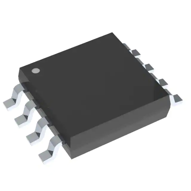
- Part No.:
- DS2450S+
- Manufacturer:
- Analog Devices Inc./Maxim Integrated
- Category:
- Analog to Digital Converters (ADC)
- Package:
- 8-SOIC (0.209", 5.30mm Width)
- Datasheet:
-
 DS2450S+.pdf
- Description:
- IC ADC 16BIT SAR 8SOIC
- Quantity:
- Payment:

- Shipping:

Inventory:2,258
Please send an inquiry. Send us your inquiry, and we will respond immediately.
Product details
Overview
DS2450S+ from Maxim Integrated is a 1-Wire quad analog-to-digital converter with four high-impedance voltage inputs, 16-bit successive-approximation architecture, user-programmable input ranges (2.56V or 5.12V), 1–16-bit resolution per channel, and integrated alarm threshold detection. It operates from a single 5V supply or parasitic power, supports multidrop 1-Wire bus topology, and targets distributed sensor monitoring in industrial control and environmental sensing systems.
For engineers reviewing the DS2450S+ datasheet, DS2450S+ pinout, DS2450S+ application, or DS2450S+ equivalent, key selection considerations include its 1-Wire interface compatibility, per-channel programmable resolution and alarm thresholds, VCC/parasitic power flexibility, 8-pin SOIC package constraints, and conditional search capability for event-driven system wake-up.
Technical Context
The DS2450S+ implements a successive-approximation ADC with a 4:1 analog multiplexer and independent SRAM-based control registers per channel. Each channel supports configurable input range (2.56V/5.12V), resolution (1–16 bits), and dual alarm thresholds (high/low), with automatic flag generation upon violation.
It uses the Dallas Semiconductor 1-Wire protocol with standard (16.3 kbps) or overdrive (142 kbps) communication modes, requires no external clock, and integrates a 16-bit CRC generator for memory read/write integrity. Power delivery is flexible: VCC-supplied (enabling concurrent bus activity during conversion) or parasitic (requiring strong 5V pullup during A/D conversion).
Key Specifications
| Parameter | Value and Actual Design Meaning |
|---|---|
| Interface | Single-wire 1-Wire bus (standard or overdrive mode) |
| Analog Inputs | Four independent high-Z inputs (AIN-A to AIN-D), each configurable as analog input or open-drain digital output |
| ADC Resolution | Programmable 1 to 16 bits per channel; always outputs 16-bit result (LSBs zero-padded if resolution < 16) |
| Input Range | User-selectable 2.56V or 5.12V full-scale range per channel |
| Power Supply | Single 4.5–5.5V VCC or parasitic power via 1-Wire bus (with strong 5V pullup during conversion) |
| Active Power | 2.5 mW typical at 5V; enables low-energy remote sensing |
| Operating Temp | -40°C to +85°C - validated for industrial ambient conditions |
| Unique ID | Factory-lasered 64-bit ROM (8-bit family code 0x20 + 48-bit serial + 8-bit CRC) |
Pinout & Package
DS2450S+ is housed in an 8-pin SOIC (208 mil) surface-mount package with exposed pad not electrically connected. Pin functions are fixed and non-multiplexed; NC pin must remain unconnected.
| Pin/Terminal | Circuit Role | Design Meaning |
|---|---|---|
| VCC | Positive supply input | Accepts 4.5–5.5V; enables VCC-powered operation and concurrent bus activity during A/D conversion |
| NC | No-connect terminal | Must be left floating; no internal connection or function |
| DATA | 1-Wire bidirectional bus line | Carries all commands, data, and presence pulses; requires external 5kΩ pullup (2.2kΩ for overdrive) |
| GND | Ground reference | Common return path for VCC, analog inputs, and 1-Wire signaling |
| AIN-A | Analog input channel A | High-impedance input; configurable as open-drain output when OE bit is set |
| AIN-B | Analog input channel B | Independent of AIN-A; supports separate range/resolution/alarm settings |
| AIN-C | Analog input channel C | Same electrical characteristics and register mapping as AIN-A/B |
| AIN-D | Analog input channel D | Final channel; recommended starting point for partial-channel use to minimize bus traffic |
Key Features
| Feature | Design Value |
|---|---|
| Per-channel programmable resolution | 1–16-bit setting stored in SRAM allows dynamic trade-off between precision and conversion time (e.g., 12-bit = ~3.84 ms for 4 channels) |
| Conditional Search support | Hardware-accelerated event notification: device responds to 1-Wire Conditional Search command only when measured voltage crosses programmed high/low thresholds |
| Dual-role I/O capability | Any analog input channel can be reconfigured as open-drain digital output without hardware change - enabling closed-loop control from same pin |
| On-chip 16-bit CRC generator | Ensures end-to-end integrity for all memory reads/writes and command sequences - eliminates need for host-side CRC calculation |
| Factory-lasered 64-bit ROM | Provides absolute device identity and traceability; 8-bit family code 0x20 signals 1-Wire protocol compliance and bus master behavior requirements |
Applications
| Industrial Sensor Node | Environmental Monitoring System |
|---|---|
Use Scenario: Distributed temperature, humidity, and supply voltage monitoring across factory floor equipment using minimal wiring. IC Role / Device Role / Timing Role: DS2450S+ acts as a 4-channel analog front-end with built-in alarm triggering, communicating over daisy-chained 1-Wire bus to central controller. Use Value: Reduces cabling complexity and node cost by eliminating local microcontrollers and dedicated ADCs; conditional search minimizes polling overhead. | Use Scenario: Remote battery-powered weather station measuring solar panel voltage, battery level, and sensor supply rails. IC Role / Device Role / Timing Role: DS2450S+ serves as ultra-low-power analog monitor, powered parasitically during communication and converting only on scheduled intervals. Use Value: 25 μW idle power enables multi-year battery life; programmable resolution extends dynamic range for varying signal amplitudes. |
| Smart Building HVAC Control | Legacy Equipment Retrofit Kit |
Use Scenario: Retrofitting analog sensors (e.g., CO₂, airflow, duct pressure) into existing 1-Wire infrastructure for centralized HVAC optimization. IC Role / Device Role / Timing Role: DS2450S+ bridges legacy analog transducers to modern 1-Wire networks, providing calibrated digitized values with alarm flags. Use Value: Enables plug-and-play integration without modifying sensor calibration or adding external signal conditioning circuitry. | Use Scenario: Adding voltage supervision to aging PLC I/O modules lacking native analog monitoring. IC Role / Device Role / Timing Role: DS2450S+ functions as a drop-in analog watchdog, detecting out-of-tolerance supply or signal voltages and alerting via conditional search. Use Value: Extends service life of legacy hardware by adding predictive maintenance capability using existing 1-Wire wiring. |
Equivalent & Alternatives
The following parts are listed as comparable options for similar 1-Wire analog monitoring applications.
| Alternative Part | Technical Difference | Application Difference | Selection Advice |
|---|---|---|---|
| DS2438Z+ | Integrated temperature sensor and current-sense ADC; no programmable input range or per-channel alarm thresholds; 10-bit fixed resolution | Optimized for battery monitoring (voltage + temp + current); lacks quad independent voltage inputs and flexible alarm logic | Select DS2438Z+ only when temperature and current measurement are required alongside voltage - not as direct functional replacement for DS2450S+ |
| MAX31826+ | 1-Wire digital temperature sensor with ±0.5°C accuracy; no analog input capability; includes internal 12-bit ADC for internal die temp only | Designed exclusively for contact temperature sensing; cannot measure external analog voltages or support user-defined alarm thresholds | Choose MAX31826+ for high-accuracy standalone temperature nodes; DS2450S+ remains required for multi-channel external voltage monitoring |
Compared with DS2450S+, DS2438Z+ adds integrated temperature/current sensing but sacrifices per-channel voltage range programming and alarm granularity, while MAX31826+ provides superior thermal accuracy but zero analog input functionality - making DS2450S+ uniquely suited for flexible, multi-voltage monitoring in constrained wiring environments.
Availability
DS2450S+ is available at Aetrix Electronics and suitable for industrial sensor nodes, environmental monitoring systems, smart building HVAC control, and legacy equipment retrofit kits requiring stable component supply and long-term 1-Wire ecosystem compatibility.
Supply support for DS2450S+ includes scheduled delivery planning, volume procurement assistance, BOM continuity management, traceable sourcing, and lifecycle availability coordination for OEM customers, industrial embedded developers, connected-device designers, and electronics production programs.
Manufacturer
Maxim Integrated (now part of Analog Devices) designs precision analog, mixed-signal, and digital ICs for industrial, automotive, and communications applications.
The DS2450S+ belongs to Maxim's 1-Wire sensor interface product line, engineered specifically to simplify distributed analog sensing over minimal-conductor wiring while maintaining device-level traceability and event-driven responsiveness.
FAQ
What is the function of the NC pin on the DS2450S+?
The NC (No Connect) pin on the DS2450S+ has no internal connection and must remain unconnected in the PCB layout. It is not tied to ground, VCC, or any internal circuitry - leaving it floating ensures correct device operation and avoids unintended biasing or leakage paths that could affect analog measurement accuracy or 1-Wire signaling integrity on the DS2450S+.
Can the DS2450S+ perform A/D conversions while powered only by the 1-Wire bus?
Yes, the DS2450S+ supports parasitic power operation, but A/D conversions require additional energy beyond what the 1-Wire bus can supply during normal signaling. When operating parasitically, the bus master must activate a strong 5V pullup on the DATA line for the duration of each conversion - otherwise the DS2450S+ will not complete accurate measurements due to insufficient supply voltage and current during sampling.
How does the DS2450S+ handle alarm conditions across multiple devices on a shared 1-Wire bus?
The DS2450S+ uses hardware-accelerated Conditional Search: when any enabled channel's measured voltage crosses its programmed high or low threshold, the DS2450S+ autonomously responds to a Conditional Search ROM command without host polling. This allows the bus master to rapidly identify only those DS2450S+ units requiring attention - reducing bus traffic and latency versus scanning all devices individually.
What is the significance of the 64-bit ROM in the DS2450S+?
The DS2450S+ features a factory-lasered 64-bit ROM containing an 8-bit family code (0x20), a unique 48-bit serial number, and an 8-bit CRC. This ROM provides absolute device identity, enables reliable multidrop addressing via Match ROM or Search ROM commands, and ensures protocol compliance - the family code tells the bus master that the DS2450S+ requires specific 1-Wire timing and command sequences.
Does the DS2450S+ support simultaneous conversion across all four channels?
No, the DS2450S+ performs sequential A/D conversions - one channel after another in fixed order (A → B → C → D) - even when multiple channels are selected in the input mask. Total conversion time scales linearly with the number of enabled channels and selected bit resolution (e.g., 4 × 12-bit conversions take ≤ 4 ms). There is no hardware support for true parallel sampling or simultaneous result capture on the DS2450S+.
DS2450S+ Specifications
- Product attributes
- Attribute value
- Manufacturer:
- Analog Devices Inc./Maxim Integrated
- Series:
- -
- Package/Case:
- 8-SOIC (0.209", 5.30mm Width)
- Packaging:
- Tube
- Product Status:
- Obsolete
- Number of Bits:
- 16
- Sampling Rate (Per Second):
- 1k
- Number of Inputs:
- 4
- Input Type:
- Single Ended
- Data Interface:
- Serial
- Configuration:
- ADC
- Ratio - S/H:ADC:
- -
- Number of A/D Converters:
- 1
- Architecture:
- SAR
- Reference Type:
- Internal
- Voltage - Supply, Analog:
- 5V
- Voltage - Supply, Digital:
- 5V
- Features:
- -
- Operating Temperature:
- -40°C ~ 85°C
- Supplier Device Package:
- 8-SOIC
- Mounting Type:
- Surface Mount
- Grade:
- -
- Qualification:
- -
DS2450S+ FAQ
1.How can I place an order for DS2450S+ through Aetrix?
Please submit a Request for Quotation (RFQ) for DS2450S+ on Aetrix. Our sales agent will provide a competitive quotation and guide you through the order confirmation once you accept the terms.
2.Are the price and stock information for DS2450S+ reliable?
The price and inventory of DS2450S+ are updated periodically and may fluctuate due to market conditions. Stock and pricing data are typically refreshed every 24 hours. Quotation validity for DS2450S+ is usually 5 days.
3.What payment methods are accepted for DS2450S+?
We accept Wire Transfer, PayPal, Credit Card, Western Union, MoneyGram, and Escrow for DS2450S+ transactions.
Note: Certain payment methods may incur a processing fee.
4.How is shipping managed for DS2450S+?
DS2450S+ orders can be shipped via leading logistics carriers, including DHL, UPS, FedEx, TNT, or Registered Mail.
Once your DS2450S+ order is processed, you will receive an email with the shipment details and tracking number.
Note: Tracking information may take up to 24 hours to appear. Express delivery typically takes 3–5 business days.
5.How can I obtain technical support or documentation for DS2450S+?
For technical support, including DS2450S+ datasheets, pinout diagrams, or application guidance, please contact our engineering support team. They can provide detailed documentation and assistance for your DS2450S+ requirements.
6.How does Aetrix verify that DS2450S+ is sourced from the original manufacturer or authorized distributors?
All DS2450S+ products on Aetrix are procured from qualified distributors and authorized channels. Our dedicated quality assurance team conducts strict verification, including traceability checks and, if necessary, third-party testing. This ensures that DS2450S+ meets industry standards.
7.What is the process for return or replacement of DS2450S+?
All DS2450S+ units undergo pre-shipment inspection (PSI). If there is an issue with DS2450S+, returns or replacements are accepted under the following conditions:
1.Quantity discrepancies, incorrect items, or visible external defects (such as breakage or corrosion), acknowledged by Aetrix.
2.The issue is reported within 90 days of delivery.
3.The DS2450S+ part is unused and in its original packaging.
Return procedure for DS2450S+:
1.Submit a request within 90 days.
2.Obtain a Return Material Authorization (RMA) from Aetrix.
DS2450S+ Tags
-
ADC081C021CIMKX/NOPB
Texas Instruments

-
MCP3021A5T-E/OT
Microchip Technology
-
TLA2024IRUGR
Texas Instruments
-
MCP3221A5T-E/OT
Microchip Technology
-
MCP3221A5T-I/OT
Microchip Technology
-
MCP3221A4T-E/OT
Microchip Technology
-
MCP3221A6T-E/OT
Microchip Technology
-
MCP3221A0T-E/OT
Microchip Technology
-
MCP3221A1T-E/OT
Microchip Technology

-
ADC121S021CIMFX/NOPB
Texas Instruments

-
MCP3001-I/MS
Microchip Technology

-
MCP3001-I/SN
Microchip Technology
Tech Hub

A practical engineering guide to 3.3V and 5V logic compatibility, input thresholds, resistor dividers, translator ICs, MOSFET level shifting, I2C pull-ups, timing limits and power-sequencing risks.

The 74HC595 uses push-pull logic outputs, while the TPIC6B595 uses 50 V open-drain DMOS sinks for higher-power loads. This guide compares timing, current limits, 3.3 V interfacing, load wiring, thermal…

The 74HC595 converts serial data into eight stable parallel outputs. This guide covers pin functions, shift and storage timing, OE and MR behavior, drive-current limits, cascading, voltage compatibilit…

A technical comparison of level-sensitive latches and edge-triggered flip-flops, covering timing windows, setup and hold limits, master–slave operation, time borrowing, race-through, HDL inference and…

A D latch stores one bit while Enable controls when data can pass. This reference covers gate-level operation, truth tables, transparency, setup and hold timing, LE versus OE, common ICs and practical …

An SR latch stores one bit through cross-coupled feedback. This engineering reference covers NOR and NAND implementations, truth tables, forbidden-state recovery, gated operation, switch debouncing, fa…

Latch circuits retain one bit through feedback. This technical reference covers SR and D latches, truth tables, transparency, timing limits, latch-versus-flip-flop behavior, applications and common log…

An engineering guide to LED driver operation, constant-current and constant-voltage outputs, linear and switching topologies, dimming, IC selection, calculations, replacement compatibility, and fault c…

Operational amplifier guide covering op amp basics, feedback, ideal vs real op amps, common configurations, buffer circuits, offset, bias current, gain-bandwidth, slew rate, rail-to-rail limits and sel…

Jumper cables guide covering safe connection order, red and black clamp placement, final ground connection, cable gauge, length, clamp quality, copper vs CCA cables, jump starter comparison and battery…


