
 My Inquiry
 My Account


Analog Devices Inc./Maxim Integrated DS2490Y
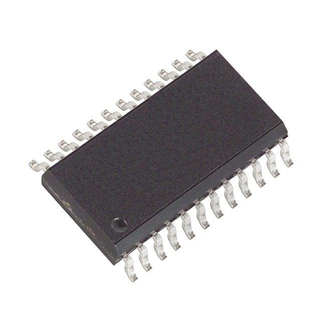
- Part No.:
- DS2490Y
- Manufacturer:
- Analog Devices Inc./Maxim Integrated
- Category:
- Controllers
- Package:
- 24-SOIC (0.295", 7.50mm Width)
- Datasheet:
-
 DS2490Y.pdf
- Description:
- IC BRIDGE CLIP USB TO 1-W 24SOIC
- Quantity:
- Payment:

- Shipping:

Inventory:3,310
Please send an inquiry. Send us your inquiry, and we will respond immediately.
Product details
Overview
DS2490Y from Maxim Integrated is a USB-to-1-Wire bridge IC that enables full-speed USB 2.0 host systems to interface with 1-Wire networks at regular, overdrive, and programmable flexible speeds. It integrates a USB-compliant transceiver, crystal-based 12MHz oscillator, active 5V pullup, and slew-rate-controlled 1-Wire I/O for reliable operation on long bus lines up to 300m. Used in iButton readers, sensor hubs, and secure authentication peripherals.
For engineers reviewing the DS2490Y datasheet, DS2490Y pinout, DS2490Y application, or DS2490Y equivalent, key selection criteria include USB remote wake-up support, programmable 1-Wire timing (tLOW1, tDSO, slew rate), stiff 5V pullup capability, crystal-referenced waveform accuracy, and compatibility with Dallas/Maxim 1-Wire devices including EEPROMs, temperature sensors, and crypto iButtons.
Technical Context
The DS2490Y implements a dedicated USB device controller with vendor-specific command handling over EP0, plus three additional endpoints: EP1 (interrupt pipe, 1ms or 10ms polling) for status and attach detection, EP2 (bulk OUT) for host-to-1-Wire data, and EP3 (bulk IN) for 1-Wire-to-host data. Its 1-Wire interface controller actively shapes rising edges using dual-current pullup (IWEAKPU/IACTPU) and supports configurable falling-edge slew rates (1V/µs typical for 300m lines).
Timing is crystal-locked via 12.0MHz fundamental-mode parallel-resonant crystal on XI/XO pins. All 1-Wire waveforms - reset/presence detect, Write-0/Write-1 time slots, and strong pullup pulses - are generated autonomously with precise control over tRSTL (512µs regular), tLOW1 (4–11µs flexible), tDSO (10–24µs), and STRONG PULLUP DURATION (predefined or infinite).
Key Specifications
| Parameter | Value and Actual Design Meaning |
|---|---|
| USB Interface | Full-speed 12Mbps USB 1.1 compliant with integrated transceiver and remote wake-up support |
| 1-Wire Speed Modes | Regular (65µs slot), Overdrive (10.4µs slot), Flexible (60–81µs slot with programmable tLOW1/tDSO) |
| 1-Wire Pullup | Stiff 5V active pullup with dual-current architecture (IWEAKPU + IACTPU) and timer-controlled duration |
| Bus Length Support | Up to 300m via slew-rate control (target tF = 4 ± 0.5µs, ~1V/µs) |
| Oscillator | Crystal-referenced 12.0MHz fundamental-mode parallel-resonant crystal (XI/XO) |
| Power Supplies | VD = 5.0V ±10% (digital & 1-Wire), VB = 3.3V ±10% (USB), VD2 externally tied to VD |
| Operating Temperature | 0°C to +70°C industrial grade |
Pinout & Package
DS2490Y is housed in a 24-pin SOIC (300-mil) package with exposed pad not internally connected. Power domains are segregated: VD/VD2 supply digital and 1-Wire circuitry; VB supplies USB transceiver; GND serves as common reference and 1-Wire return path.
| Pin/Terminal | Circuit Role | Design Meaning |
|---|---|---|
| VD | Power input | Main 5V supply for digital logic and 1-Wire interface; must be decoupled locally |
| VD2 | Power input | Second 5V supply pin; externally tied to VD - not internally connected |
| VB | Power input | 3.3V supply for USB transceiver; regulated from USB VBUS |
| D+, D− | USB differential I/O | Full-speed USB data pair; require 27Ω series resistors and proper PCB routing |
| 1-Wire | 1-Wire bidirectional I/O | Single-wire interface with active pullup, slew control, and non-TTL threshold sensing |
| PMOD | Input | Reserved for future use; must be tied to GND |
| SUSO | Output | Open-drain suspend status indicator; requires external pullup to monitor USB active/suspend state |
| XI, XO | Oscillator interface | Connects to 12.0MHz crystal or CMOS clock source; defines all 1-Wire timing precision |
| GND | Ground reference | Common ground for USB, digital, and 1-Wire return paths |
| NC | No connect | Factory test or reserved; must remain unconnected |
Key Features
| Feature | Design Value |
|---|---|
| Programmable 1-Wire timing | Independent control of tLOW1 (4–11µs), tDSO (10–24µs), and pulldown slew rate enables optimization for short or 300m bus topologies |
| Active 5V pullup with dual-current architecture | Switches from weak (IWEAKPU) to strong (IACTPU) current at VIAPO threshold, reducing rise time and improving noise margin on large networks |
| USB remote wake-up | Generates resume signaling upon 1-Wire device attachment while host is suspended - eliminates polling and reduces system power |
| Crystal-locked 1-Wire waveform generation | 12MHz oscillator ensures precise, jitter-free reset, read/write, and pulse timing across temperature and voltage |
| Vendor-specific USB command set | Three-tiered command architecture (Control/Communication/Mode) enables deterministic 1-Wire transaction sequencing without host CPU timing constraints |
Applications
| iButton Authentication Terminal | Industrial Sensor Hub |
|---|---|
Use Scenario: Desktop or kiosk-based physical access control using iButton tokens for user identification and privilege verification. IC Role / Device Role / Timing Role: DS2490Y acts as the USB-facing 1-Wire master, handling token enumeration, challenge-response crypto handshakes, and secure memory reads - all timed by its internal crystal. Use Value: Eliminates need for custom USB firmware; enables plug-and-play iButton integration into Windows/Linux host systems via standard USB HID or vendor driver stacks. | Use Scenario: Centralized monitoring of distributed 1-Wire temperature, humidity, and voltage sensors in factory automation or building management systems. IC Role / Device Role / Timing Role: DS2490Y bridges USB-connected gateway hardware to multi-drop 1-Wire sensor networks, managing presence detection, address resolution, and sequential data reads with configurable tLOW1/tDSO for long cable runs. Use Value: Supports >100m sensor cabling without signal degradation via slew-rate tuning and active pullup - avoids repeaters or RS-485 conversion layers. |
| Secure Firmware Programming Adapter | Legacy System Modernization Interface |
Use Scenario: Field-programmable cryptographic keys and firmware images into DS2438 or DS2465 secure EEPROMs used in medical or aerospace devices. IC Role / Device Role / Timing Role: DS2490Y executes precise strong pullup pulses (STRONG PULLUP DURATION mode) required for EEPROM write cycles and verifies response timing per DS2438 spec. Use Value: Guarantees correct 5V pulse width and voltage stability during programming - prevents bit errors or memory corruption caused by marginal pullup sources. | Use Scenario: Retrofitting legacy equipment (e.g., HVAC controllers) with USB connectivity to replace aging serial or parallel interfaces. IC Role / Device Role / Timing Role: DS2490Y serves as protocol translator between modern USB hosts and existing 1-Wire sensor/actuator infrastructure - no firmware changes needed on legacy nodes. Use Value: Preserves investment in installed 1-Wire devices while enabling cloud telemetry, remote diagnostics, and OTA updates via standard USB drivers. |
Equivalent & Alternatives
The following parts are listed as comparable options for similar USB-to-1-Wire bridge applications.
| Alternative Part | Technical Difference | Application Difference | Selection Advice |
|---|---|---|---|
| DS2480B | Legacy UART-to-1-Wire bridge; requires external USB-UART converter (e.g., FTDI); no integrated USB transceiver or remote wake-up | Limited to RS-232/UART host interfaces; lacks crystal timing precision and flexible speed control | Select DS2480B only when reusing existing UART-based host firmware and cost sensitivity outweighs USB integration benefits |
| DS2490Z+ | Same die as DS2490Y but in 24-pin TSSOP (150-mil) package; identical electrical specs and pinout mapping | Requires different PCB footprint and thermal layout; same functional behavior and timing performance | Choose DS2490Z+ for space-constrained designs where SOIC height or thermal mass is prohibitive |
Compared with DS2490Y, DS2480B adds external component overhead and timing uncertainty, while DS2490Z+ offers identical functionality in a smaller package - making DS2490Y optimal for industrial USB adapters requiring robust SOIC mounting and thermal stability.
Availability
DS2490Y is available at Aetrix Electronics and suitable for industrial sensor hubs, iButton authentication terminals, secure firmware programming adapters, and legacy system modernization interfaces requiring stable component supply and long-term lifecycle support.
Supply support for DS2490Y includes scheduled delivery planning, volume procurement assistance, BOM continuity management, traceable sourcing, and lifecycle availability coordination for OEM customers, industrial embedded developers, connected-device designers, and electronics production programs.
Manufacturer
Maxim Integrated (now part of Analog Devices) is a semiconductor company specializing in analog, mixed-signal, and digital ICs for industrial, communications, and computing applications.
The DS2490Y belongs to Maxim's 1-Wire interface product line, designed specifically to simplify USB host connectivity to 1-Wire networks while maintaining strict timing compliance and electromagnetic compatibility on extended bus lengths.
FAQ
What is the primary function of the DS2490Y in a USB-to-1-Wire system?
The DS2490Y serves as a dedicated bridge IC that translates USB host commands into precisely timed 1-Wire transactions. It handles all physical layer responsibilities - including crystal-referenced waveform generation, active 5V pullup, slew-rate-controlled edges, and USB enumeration - allowing host software to interact with 1-Wire devices via vendor-specific USB commands without real-time timing constraints. This makes DS2490Y essential for reliable, standards-compliant 1-Wire communication over USB.
Does the DS2490Y require an external crystal, and why is it critical?
Yes, the DS2490Y requires a 12.0MHz fundamental-mode parallel-resonant crystal connected between XI and XO pins. This crystal establishes the timing reference for all 1-Wire waveforms - including reset pulses, read/write slots, and strong pullup durations - ensuring compliance with Dallas/Maxim 1-Wire timing specifications across voltage and temperature. Without this crystal, DS2490Y cannot generate accurate 1-Wire signals, and communication will fail. A CMOS clock source may substitute, but crystal remains the recommended solution for stability.
How does the DS2490Y support long 1-Wire bus lengths up to 300 meters?
The DS2490Y supports long 1-Wire buses through three integrated features: (1) slew-rate-controlled falling edges (configurable via PULLDOWN SLEW RATE mode command to target ~1V/µs), (2) active dual-current 5V pullup that accelerates bus rise time, and (3) non-TTL input threshold sensing that improves noise margin. These features collectively reduce ringing, improve signal integrity, and maintain timing margins on high-capacitance lines - validated for reliable operation on 300m networks when configured per DS2490Y datasheet guidelines.
Can the DS2490Y wake up a suspended USB host system, and how is this enabled?
Yes, the DS2490Y supports USB remote wake-up: when enabled via the DEVICE_REMOTE_WAKEUP feature selector, it detects 1-Wire device attachment (e.g., iButton insertion) and initiates USB resume signaling to awaken a suspended host. This function is disabled by default and must be explicitly enabled by host software using a SET_FEATURE USB core command. The SUSO pin provides local indication of USB suspend state, aiding in low-power system design. DS2490Y thus enables energy-efficient, event-driven host interaction without continuous polling.
What are the power supply requirements for the DS2490Y, and how are they segregated?
The DS2490Y requires three distinct power domains: VD (5.0V ±10%) powers digital logic and the 1-Wire interface; VD2 is a second 5V pin that must be externally tied to VD (not internally connected); VB (3.3V ±10%) supplies the USB transceiver and is typically derived from USB VBUS via an LDO. This segregation isolates noise-sensitive USB signaling from 1-Wire switching transients, ensuring robust communication. All supplies require local ceramic decoupling per the DS2490Y layout guidelines.
DS2490Y Specifications
- Product attributes
- Attribute value
- Manufacturer:
- Analog Devices Inc./Maxim Integrated
- Package/Case:
- 24-SOIC (0.295", 7.50mm Width)
- Programmable:
- Not Verified
- Protocol:
- USB
- Function:
- Bridge, USB to 1-Wire®
- Interface:
- 1-Wire®
- Standards:
- -
- Voltage - Supply:
- 3V ~ 5.5V
- Current - Supply:
- 20mA
- Operating Temperature:
- 0°C ~ 70°C
- Supplier Device Package:
- 24-SOIC
- Grade:
- -
- Qualification:
- -
DS2490Y FAQ
1.How can I place an order for DS2490Y through Aetrix?
Please submit a Request for Quotation (RFQ) for DS2490Y on Aetrix. Our sales agent will provide a competitive quotation and guide you through the order confirmation once you accept the terms.
2.Are the price and stock information for DS2490Y reliable?
The price and inventory of DS2490Y are updated periodically and may fluctuate due to market conditions. Stock and pricing data are typically refreshed every 24 hours. Quotation validity for DS2490Y is usually 5 days.
3.What payment methods are accepted for DS2490Y?
We accept Wire Transfer, PayPal, Credit Card, Western Union, MoneyGram, and Escrow for DS2490Y transactions.
Note: Certain payment methods may incur a processing fee.
4.How is shipping managed for DS2490Y?
DS2490Y orders can be shipped via leading logistics carriers, including DHL, UPS, FedEx, TNT, or Registered Mail.
Once your DS2490Y order is processed, you will receive an email with the shipment details and tracking number.
Note: Tracking information may take up to 24 hours to appear. Express delivery typically takes 3–5 business days.
5.How can I obtain technical support or documentation for DS2490Y?
For technical support, including DS2490Y datasheets, pinout diagrams, or application guidance, please contact our engineering support team. They can provide detailed documentation and assistance for your DS2490Y requirements.
6.How does Aetrix verify that DS2490Y is sourced from the original manufacturer or authorized distributors?
All DS2490Y products on Aetrix are procured from qualified distributors and authorized channels. Our dedicated quality assurance team conducts strict verification, including traceability checks and, if necessary, third-party testing. This ensures that DS2490Y meets industry standards.
7.What is the process for return or replacement of DS2490Y?
All DS2490Y units undergo pre-shipment inspection (PSI). If there is an issue with DS2490Y, returns or replacements are accepted under the following conditions:
1.Quantity discrepancies, incorrect items, or visible external defects (such as breakage or corrosion), acknowledged by Aetrix.
2.The issue is reported within 90 days of delivery.
3.The DS2490Y part is unused and in its original packaging.
Return procedure for DS2490Y:
1.Submit a request within 90 days.
2.Obtain a Return Material Authorization (RMA) from Aetrix.
DS2490Y Tags

-
PTN5150AHXMP
NXP Semiconductors

-
USB3740B-AI9-TR
Microchip Technology

-
USB3740B-AI2-TR
Microchip Technology

-
USB3300-EZK-TR
Microchip Technology
-
USB3300-EZK
Microchip Technology

-
FUSB340TMX
onsemi

-
FUSB302BMPX
onsemi

-
DP83826IRHBR
Texas Instruments

-
MCP2518FDT-E/QBB
Microchip Technology
-
FUSB302MPX
onsemi

-
MCP2518FDT-E/SL
Microchip Technology

-
FT260Q-R
FTDI, Future Technology Devices International Ltd
Tech Hub

A practical engineering guide to 3.3V and 5V logic compatibility, input thresholds, resistor dividers, translator ICs, MOSFET level shifting, I2C pull-ups, timing limits and power-sequencing risks.

The 74HC595 uses push-pull logic outputs, while the TPIC6B595 uses 50 V open-drain DMOS sinks for higher-power loads. This guide compares timing, current limits, 3.3 V interfacing, load wiring, thermal…

The 74HC595 converts serial data into eight stable parallel outputs. This guide covers pin functions, shift and storage timing, OE and MR behavior, drive-current limits, cascading, voltage compatibilit…

A technical comparison of level-sensitive latches and edge-triggered flip-flops, covering timing windows, setup and hold limits, master–slave operation, time borrowing, race-through, HDL inference and…

A D latch stores one bit while Enable controls when data can pass. This reference covers gate-level operation, truth tables, transparency, setup and hold timing, LE versus OE, common ICs and practical …

An SR latch stores one bit through cross-coupled feedback. This engineering reference covers NOR and NAND implementations, truth tables, forbidden-state recovery, gated operation, switch debouncing, fa…

Latch circuits retain one bit through feedback. This technical reference covers SR and D latches, truth tables, transparency, timing limits, latch-versus-flip-flop behavior, applications and common log…

An engineering guide to LED driver operation, constant-current and constant-voltage outputs, linear and switching topologies, dimming, IC selection, calculations, replacement compatibility, and fault c…

Operational amplifier guide covering op amp basics, feedback, ideal vs real op amps, common configurations, buffer circuits, offset, bias current, gain-bandwidth, slew rate, rail-to-rail limits and sel…

Jumper cables guide covering safe connection order, red and black clamp placement, final ground connection, cable gauge, length, clamp quality, copper vs CCA cables, jump starter comparison and battery…


