
 My Inquiry
 My Account


Analog Devices Inc./Maxim Integrated DS2502X1#U
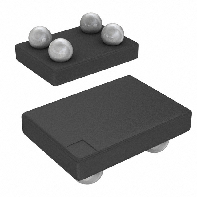
- Part No.:
- DS2502X1#U
- Manufacturer:
- Analog Devices Inc./Maxim Integrated
- Category:
- Memory
- Package:
- 4-UFBGA, WLCSP
- Datasheet:
-
 DS2502X1#U.pdf
- Description:
- IC EPROM 1KBIT 1-WIRE 4WLP
- Quantity:
- Payment:

- Shipping:

Inventory:1,775
Please send an inquiry. Send us your inquiry, and we will respond immediately.
Product details
Overview
DS2502X1#U from Maxim Integrated is a 1-Wire add-only memory IC with factory-lasered 64-bit ROM ID (Family Code 09h), 1024-bit EPROM partitioned into four 256-bit pages, and page-level write protection - used for asset tracking, calibration storage, and maintenance record logging in industrial and medical devices.
For engineers reviewing the DS2502X1#U datasheet, DS2502X1#U pinout, DS2502X1#U application, or DS2502X1#U equivalent, this device supports parasitic power operation from 2.8V–6.0V, requires 11.5–12.0V programming pulses, delivers guaranteed unique traceability via laser-programmed serial number, and interfaces via single-pin 1-Wire protocol at up to 16.3 kbps.
Technical Context
The DS2502X1#U implements a hierarchical 1-Wire protocol requiring ROM Function Commands (e.g., Read ROM, Skip ROM) before enabling Memory Function Commands (e.g., Write Memory [0Fh], Read Data/Generate 8-bit CRC [C3h]). Its internal architecture includes an 8-bit scratchpad buffer, on-chip 8-bit CRC generator, and parasite power harvesting circuitry.
EPROM programming operates bit-wise (1→0 only), with each byte verified post-pulse via read-back; status bytes control page write-protection and support page address redirection (e.g., FDh → page 2) for software-managed data patching without physical reprogramming.
Key Specifications
| Parameter | Value and Actual Design Meaning |
|---|---|
| Memory Type | 1024-bit EPROM (4 × 256-bit pages) + 64-bit lasered ROM |
| Interface | Single-pin 1-Wire bus (open-drain, parasitic power capable) |
| Operating Voltage | 2.8V–6.0V for read; 11.5V–12.0V programming pulse required |
| Temperature Range | -40°C to +85°C - validated for industrial-grade reliability |
| Data Integrity | On-device 8-bit CRC generation per page during read; factory-lasered CRC over 64-bit ROM |
| Write Protection | Per-page permanent write-disable via status byte bits - prevents tampering after programming |
| Communication Speed | Up to 16.3 kbps - enables fast interrogation in multi-drop sensor networks |
Pinout & Package
DS2502X1#U uses a 4-terminal Wafer-Level Package (WLP), qualified for electro-mechanical contact applications. Laser-marked top-side contacts are not visible; pin 1A/1B = DATA, pin 2A/2B = GND.
| Pin/Terminal | Circuit Role | Design Meaning |
|---|---|---|
| 1A / 1B | DATA (1-Wire I/O) | Bi-directional open-drain signal line - carries power, clock, address, and data via time-division multiplexing |
| 2A / 2B | GND | Ground reference for parasitic power capacitor discharge and logic reference - dual terminals reduce contact resistance |
Key Features
| Feature | Design Value |
|---|---|
| Guaranteed Unique 64-Bit ROM ID | Factory-lasered 48-bit serial number + 8-bit family code (09h) + 8-bit CRC - enables absolute device-level traceability without host-side ID management |
| Add-Only Memory Architecture | Bits change only from 1→0; allows appending new calibration or revision data without erasing prior records - critical for audit-compliant systems |
| Page Address Redirection | Status byte-controlled mapping (e.g., FDh → page 2) lets firmware invalidate obsolete data and redirect reads to updated pages - eliminates need for full-memory reprogramming |
| Parasitic Power Operation | No VCC pin required - energy harvested from 1-Wire line during high states powers all read operations - simplifies PCB layout and reduces BOM count |
| Page-Level Write Protection | Independent 1-bit enable per 256-bit page stored in EPROM status bytes - prevents accidental or malicious overwrite of certified calibration constants |
Applications
| Asset Tracking Tag | Medical Device Calibration |
|---|---|
Use Scenario: Embedded in reusable surgical instruments to log sterilization cycles, usage count, and service history. IC Role / Device Role / Timing Role: 1-Wire slave providing tamper-proof, non-volatile identity and event logging via single-wire interface. Use Value: Eliminates manual recordkeeping; enables automated compliance reporting using factory-guaranteed unique ID and write-protected memory pages. |
Use Scenario: Mounted on diagnostic ultrasound transducers to store factory calibration coefficients and firmware revision metadata. IC Role / Device Role / Timing Role: Add-only memory storing immutable calibration data accessed during power-up by host controller. Use Value: Ensures regulatory traceability (FDA 21 CFR Part 11); prevents unauthorized modification via hardware-enforced page write protection. |
| Industrial Sensor Node | Access Control Token |
Use Scenario: Integrated into environmental monitoring sensors deployed in hazardous locations where wiring must be minimized. IC Role / Device Role / Timing Role: Parasitic-powered 1-Wire identity and configuration storage - no local power rail needed. Use Value: Reduces cabling complexity and explosion risk; enables multi-drop topology with up to 100+ nodes on one microcontroller pin. |
Use Scenario: Embedded in secure access fobs for facility entry systems requiring cryptographic key binding to physical token identity. IC Role / Device Role / Timing Role: Source of cryptographically verifiable, unclonable 64-bit ROM ID tied to device-specific secrets. Use Value: Provides hardware-rooted identity for challenge-response authentication - immune to software cloning due to laser-programmed ROM. |
Equivalent & Alternatives
The following parts are listed as comparable options for similar 1-Wire memory applications.
| Alternative Part | Technical Difference | Application Difference | Selection Advice |
|---|---|---|---|
| DS2430A | 256-bit EEPROM (not EPROM); supports full read/write cycles (0↔1), no page redirection; lower memory density | Lacks permanent write protection and page-level invalidation - unsuitable for audit-trail or calibration-critical use cases | Choose DS2430A only when field-updatable memory (not add-only) and smaller capacity are acceptable trade-offs. |
| DS28EC20 | 20kb 1-Wire EEPROM with SHA-256 crypto engine; supports password-protected writes and memory locking | Includes cryptographic authentication - adds security layer but increases cost and firmware complexity vs. DS2502X1#U's simplicity | Select DS28EC20 if cryptographic integrity verification is required; otherwise DS2502X1#U offers lower-cost, simpler traceability. |
Compared with DS2430A and DS28EC20, the DS2502X1#U uniquely combines guaranteed factory-unique ID, add-only memory semantics, and page-level write protection - making it optimal for calibration, maintenance, and regulatory traceability where data immutability and minimal interface overhead are primary design constraints.
Availability
DS2502X1#U is available at Aetrix Electronics and suitable for asset tracking, medical device calibration, and industrial sensor node applications requiring stable component supply, long-term lifecycle support, and RoHS-compliant packaging.
Supply support for DS2502X1#U includes scheduled delivery planning, volume procurement assistance, BOM continuity management, traceable sourcing, and lifecycle availability coordination for OEM customers, industrial embedded developers, connected-device designers, and electronics production programs.
Manufacturer
Maxim Integrated (now part of Analog Devices) designs precision analog, mixed-signal, and digital ICs for industrial, medical, and communications markets - emphasizing reliability, integration, and low-power operation.
The DS2502X1#U belongs to Maxim's 1-Wire memory product line, engineered specifically for secure, low-pin-count identification and immutable data storage in resource-constrained embedded systems.
FAQ
What is the function of the 64-bit ROM ID in DS2502X1#U?
The 64-bit ROM ID in DS2502X1#U consists of an 8-bit family code (09h), 48-bit factory-lasered serial number, and 8-bit CRC - providing guaranteed unique device identity for absolute traceability. This ID is read-only, laser-programmed during manufacturing, and used by 1-Wire bus masters to identify and singulate individual DS2502X1#U devices on shared buses without external addressing logic.
Can DS2502X1#U be reprogrammed multiple times?
Yes, DS2502X1#U supports multiple programming cycles, but only in add-only mode: bits transition from logical 1 to 0, never reversed. New data can be appended to unused EPROM space or replace outdated pages via status-byte-controlled address redirection. Each write requires a 12V programming pulse, and pages can be permanently write-protected after final programming to prevent tampering.
Does DS2502X1#U require an external power supply?
No, DS2502X1#U operates with parasitic power - deriving all energy for read operations from the 1-Wire data line via internal capacitance. Only programming requires an external 11.5–12.0V pulse on the same DATA line. This eliminates the need for a dedicated VCC pin or power rail, simplifying integration into space- and cost-constrained designs.
What package type does DS2502X1#U use, and how is it mounted?
DS2502X1#U uses a 4-terminal Wafer-Level Package (WLP), marked "X1" in the ordering code. It is designed for electro-mechanical contact applications - not soldering - with laser-marked top-side contacts (1A/1B = DATA, 2A/2B = GND) that interface via spring-loaded pogo pins or compliant interconnects. Mounting requires mechanical retention, not reflow soldering.
How does page address redirection work in DS2502X1#U?
DS2502X1#U uses four Page Address Redirection Bytes in its EPROM Status Memory to invalidate obsolete data pages. For example, writing FDh to the redirection byte for page 1 tells host firmware to read updated data from page 2 (one's complement of FDh). The DS2502X1#U hardware does not auto-redirect - firmware interprets these bytes to route reads, enabling software-managed data patching without reprogramming the original page.
DS2502X1#U Specifications
- Product attributes
- Attribute value
- Manufacturer:
- Analog Devices Inc./Maxim Integrated
- Series:
- -
- Package/Case:
- 4-UFBGA, WLCSP
- Packaging:
- Bulk
- Product Status:
- Obsolete
- Programmable:
- Not Verified
- Memory Type:
- Non-Volatile
- Memory Format:
- EPROM
- Technology:
- EPROM - OTP
- Memory Size:
- 1Kbit
- Memory Organization:
- 128 x 8
- Memory Interface:
- 1-Wire®
- Clock Frequency:
- -
- Write Cycle Time - Word, Page:
- -
- Access Time:
- -
- Voltage - Supply:
- 2.8V ~ 6V
- Operating Temperature:
- -40°C ~ 85°C (TA)
- Grade:
- -
- Qualification:
- -
- Mounting Type:
- Surface Mount
- Supplier Device Package:
- 4-WLP (1.62x0.93)
DS2502X1#U FAQ
1.How can I place an order for DS2502X1#U through Aetrix?
Please submit a Request for Quotation (RFQ) for DS2502X1#U on Aetrix. Our sales agent will provide a competitive quotation and guide you through the order confirmation once you accept the terms.
2.Are the price and stock information for DS2502X1#U reliable?
The price and inventory of DS2502X1#U are updated periodically and may fluctuate due to market conditions. Stock and pricing data are typically refreshed every 24 hours. Quotation validity for DS2502X1#U is usually 5 days.
3.What payment methods are accepted for DS2502X1#U?
We accept Wire Transfer, PayPal, Credit Card, Western Union, MoneyGram, and Escrow for DS2502X1#U transactions.
Note: Certain payment methods may incur a processing fee.
4.How is shipping managed for DS2502X1#U?
DS2502X1#U orders can be shipped via leading logistics carriers, including DHL, UPS, FedEx, TNT, or Registered Mail.
Once your DS2502X1#U order is processed, you will receive an email with the shipment details and tracking number.
Note: Tracking information may take up to 24 hours to appear. Express delivery typically takes 3–5 business days.
5.How can I obtain technical support or documentation for DS2502X1#U?
For technical support, including DS2502X1#U datasheets, pinout diagrams, or application guidance, please contact our engineering support team. They can provide detailed documentation and assistance for your DS2502X1#U requirements.
6.How does Aetrix verify that DS2502X1#U is sourced from the original manufacturer or authorized distributors?
All DS2502X1#U products on Aetrix are procured from qualified distributors and authorized channels. Our dedicated quality assurance team conducts strict verification, including traceability checks and, if necessary, third-party testing. This ensures that DS2502X1#U meets industry standards.
7.What is the process for return or replacement of DS2502X1#U?
All DS2502X1#U units undergo pre-shipment inspection (PSI). If there is an issue with DS2502X1#U, returns or replacements are accepted under the following conditions:
1.Quantity discrepancies, incorrect items, or visible external defects (such as breakage or corrosion), acknowledged by Aetrix.
2.The issue is reported within 90 days of delivery.
3.The DS2502X1#U part is unused and in its original packaging.
Return procedure for DS2502X1#U:
1.Submit a request within 90 days.
2.Obtain a Return Material Authorization (RMA) from Aetrix.
DS2502X1#U Tags

-
M24C02-WMN6TP
STMicroelectronics

-
AT24C02C-XHM-T
Microchip Technology

-
AT21CS01-STUM10-T
Microchip Technology

-
AT24C02C-SSHM-T
Microchip Technology

-
24LC01BT-I/OT
Microchip Technology

-
M24C02-FMC6TG
STMicroelectronics
-
AT24CS02-SSHM-T
Microchip Technology

-
93LC46BT-I/OT
Microchip Technology
-
AT24C04C-SSHM-T
Microchip Technology

-
24LC01BT-I/SN
Microchip Technology
-
24AA02UIDT-I/OT
Microchip Technology

-
AT24C08C-STUM-T
Microchip Technology
Tech Hub

A practical engineering guide to 3.3V and 5V logic compatibility, input thresholds, resistor dividers, translator ICs, MOSFET level shifting, I2C pull-ups, timing limits and power-sequencing risks.

The 74HC595 uses push-pull logic outputs, while the TPIC6B595 uses 50 V open-drain DMOS sinks for higher-power loads. This guide compares timing, current limits, 3.3 V interfacing, load wiring, thermal…

The 74HC595 converts serial data into eight stable parallel outputs. This guide covers pin functions, shift and storage timing, OE and MR behavior, drive-current limits, cascading, voltage compatibilit…

A technical comparison of level-sensitive latches and edge-triggered flip-flops, covering timing windows, setup and hold limits, master–slave operation, time borrowing, race-through, HDL inference and…

A D latch stores one bit while Enable controls when data can pass. This reference covers gate-level operation, truth tables, transparency, setup and hold timing, LE versus OE, common ICs and practical …

An SR latch stores one bit through cross-coupled feedback. This engineering reference covers NOR and NAND implementations, truth tables, forbidden-state recovery, gated operation, switch debouncing, fa…

Latch circuits retain one bit through feedback. This technical reference covers SR and D latches, truth tables, transparency, timing limits, latch-versus-flip-flop behavior, applications and common log…

An engineering guide to LED driver operation, constant-current and constant-voltage outputs, linear and switching topologies, dimming, IC selection, calculations, replacement compatibility, and fault c…

Operational amplifier guide covering op amp basics, feedback, ideal vs real op amps, common configurations, buffer circuits, offset, bias current, gain-bandwidth, slew rate, rail-to-rail limits and sel…

Jumper cables guide covering safe connection order, red and black clamp placement, final ground connection, cable gauge, length, clamp quality, copper vs CCA cables, jump starter comparison and battery…


