
 My Inquiry
 My Account


Analog Devices Inc./Maxim Integrated DS2505P+T&R
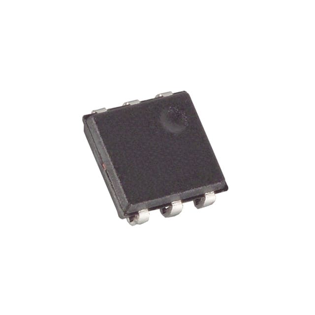
- Part No.:
- DS2505P+T&R
- Manufacturer:
- Analog Devices Inc./Maxim Integrated
- Category:
- Memory
- Package:
- 6-SMD, J-Lead
- Datasheet:
-
 DS2505P+T&R.pdf
- Description:
- IC EPROM 16KBIT 1-WIRE 6TSOC
- Quantity:
- Payment:

- Shipping:

Inventory:15,617
Please send an inquiry. Send us your inquiry, and we will respond immediately.
Product details
Overview
DS2505P+T&R from Maxim Integrated (now Analog Devices) is a 16 kbit add-only EPROM IC operating on the 1-Wire® bus, featuring a factory-lasered 64-bit ROM (8-bit family code 0BH + 48-bit serial number + 8-bit CRC), 64 pages of 256-bit memory, single-pin parasitic-power operation, and page-level write protection. It enables traceable asset tagging and calibration storage in industrial sensors and medical devices.
For engineers reviewing the DS2505P+T&R datasheet, DS2505P+T&R pinout, DS2505P+T&R application, or DS2505P+T&R equivalent, key selection criteria include 1-Wire protocol compliance, 2.8–6.0 V read voltage range, 11.5–12.0 V programming requirement, TSOC package dimensions (3.7 × 4.0 × 1.5 mm), and guaranteed-unique 48-bit serial identity for secure device authentication.
Technical Context
The DS2505P+T&R implements a hierarchical 1-Wire protocol stack requiring ROM Function Commands (Read/Match/Search/Skip ROM) before enabling Memory Function Commands (Read/Write Memory, Read/Write Status, Extended Read). Its internal architecture separates 64-bit lasered ROM, 16384-bit EPROM data memory, and 704-bit EPROM status memory - with dedicated scratchpad buffering and CRC validation for each transaction.
Power is derived entirely from the 1-Wire line via parasitic capacitance during high periods; programming requires externally pulsed 12 V at 10 mA for 480 µs per byte. Page redirection is implemented via 64 one's-complement address bytes in status memory (100H–13FH), enabling software-managed data patching without physical erasure.
Key Specifications
| Parameter | Value and Actual Design Meaning |
|---|---|
| Total memory | 16384 bits EPROM (64 × 256-bit pages) + 704 bits status memory |
| Interface | Single-pin 1-Wire® bus (no clock, no address lines; bidirectional half-duplex) |
| Read voltage range | 2.8 V to 6.0 V across –40°C to +85°C ambient |
| Programming voltage | 11.5 V to 12.0 V applied as 480 µs pulses; requires external HV driver |
| Family code | 0BH (hex), used by 1-Wire master to identify DS2505 protocol requirements |
| Data rate | Up to 16.3 kbits/s (standard speed); supports speed-write mode (F3H/F5H) |
| Write protection | Per-page bit in status memory (000H–007H); irreversible once programmed |
Pinout & Package
DS2505P+T&R is housed in a 6-pin TSOC surface-mount package (3.7 × 4.0 × 1.5 mm), RoHS-compliant and lead-free. Pin 1 is DATA, Pin 2 is GND; Pins 3–6 are no-connect (NC).
| Pin/Terminal | Circuit Role | Design Meaning |
|---|---|---|
| 1 | DATA | 1-Wire bidirectional data line; supplies parasitic power and carries all commands/data/CRC |
| 2 | GND | Ground reference for 1-Wire signaling and internal circuitry |
| 3–6 | NC | No internal connection; must remain unconnected per datasheet |
Key Features
| Feature | Design Value |
|---|---|
| Add-only memory architecture | Enables appending new data without erasing existing content; bits change only 1→0 |
| Page address redirection | 64 redirection bytes (100H–13FH) allow software to invalidate and relocate entire 32-byte pages |
| Factory-lasered 64-bit ROM | Guarantees globally unique identity (48-bit serial + 8-bit CRC + 8-bit family code 0BH) |
| Two-tier CRC validation | 16-bit CRC verified per command, per page, and per redirection byte - ensures data integrity |
| Speed-write mode (F3H/F5H) | Omits intermediate CRC checks to reduce programming time by 976 µs per byte |
Applications
| Asset Tracking Tag | Calibration Data Storage |
|---|---|
|
Use Scenario: Embedded in industrial equipment or test fixtures to store manufacturing lot ID, firmware version, and service history. IC Role / Device Role / Timing Role: 1-Wire slave device providing tamper-resistant, read-on-demand identification and revision tracking. Use Value: Eliminates need for separate EEPROM + microcontroller; single-wire interface reduces PCB routing complexity and BOM count. |
Use Scenario: Mounted on precision sensors (e.g., pressure transducers, thermocouple modules) to retain factory calibration coefficients. IC Role / Device Role / Timing Role: Nonvolatile memory storing 32-byte calibration pages, write-protected after initial programming. Use Value: Enables field recalibration via redirected pages while preserving original coefficients for audit trail compliance. |
| Maintenance Record Keeper | Access Credential Token |
|
Use Scenario: Attached to HVAC units or medical imaging hardware to log service dates, technician IDs, and part replacements. IC Role / Device Role / Timing Role: Add-only EPROM recording timestamped maintenance entries using page redirection for chronological updates. Use Value: Provides immutable, time-ordered record without battery or complex file system - readable by low-cost 1-Wire readers. |
Use Scenario: Integrated into physical access tokens (e.g., iButton-style keys) for building entry systems requiring unique device identity. IC Role / Device Role / Timing Role: 64-bit ROM authenticator with guaranteed uniqueness; no user memory required for basic credentialing. Use Value: Leverages factory-lasered serial number as cryptographic root-of-trust; eliminates need for secure provisioning infrastructure. |
Equivalent & Alternatives
The following parts are listed as comparable options for similar 1-Wire memory applications.
| Alternative Part | Technical Difference | Application Difference | Selection Advice |
|---|---|---|---|
| DS2430A+ | 256-byte EEPROM (not EPROM); supports standard 1-Wire read/write; no page redirection or add-only constraint | Used where frequent rewrites are needed (e.g., runtime counters); lacks permanent audit trail capability | Select DS2430A+ when rewrite cycles > 10⁵ are required; DS2505P+T&R preferred for write-once, tamper-evident use cases |
| DS28EC20 | 20 kbit 1-Wire EEPROM with SHA-256 authentication; supports cryptographic challenge-response; no laser ROM | Deployed in secure supply chain tracking where cryptographic verification is mandated (e.g., DoD, FDA) | Choose DS28EC20 for authenticated data integrity; DS2505P+T&R remains optimal for cost-sensitive, non-crypto traceability |
Compared with DS2430A+ and DS28EC20, the DS2505P+T&R uniquely combines guaranteed-unique factory ROM, irreversible add-only memory, and software-managed page redirection - making it irreplaceable for applications requiring immutable, auditable data histories without cryptographic overhead.
Availability
DS2505P+T&R is available at Aetrix Electronics and suitable for industrial sensor calibration, medical device asset tagging, equipment maintenance logging, and secure access credentialing requiring stable component supply and long-term lifecycle support.
Supply support for DS2505P+T&R includes scheduled delivery planning, volume procurement assistance, BOM continuity management, traceable sourcing, and lifecycle availability coordination for OEM customers, industrial embedded developers, connected-device designers, and electronics production programs.
Manufacturer
Maxim Integrated (acquired by Analog Devices in 2021) designs high-performance analog and mixed-signal ICs for industrial, automotive, and communications markets.
The DS2505P+T&R belongs to Maxim's 1-Wire memory product line, engineered specifically for low-pin-count, parasitic-powered identification and traceability in space-constrained, cost-sensitive embedded systems.
FAQ
What is the function of the DS2505P+T&R in a 1-Wire system?
The DS2505P+T&R serves as a tamper-evident, add-only memory node on a 1-Wire bus. It provides factory-guaranteed unique identification via its 64-bit lasered ROM and stores up to 16 kbit of user data in 64 programmable pages. Its role is to enable traceability and calibration retention in systems where minimal wiring, low cost, and data immutability are critical - such as industrial sensors and medical devices. The DS2505P+T&R does not require external power or clock signals, drawing all operating energy parasitically from the 1-Wire line.
Can the DS2505P+T&R be reprogrammed multiple times?
Yes, the DS2505P+T&R supports multiple programming operations, but only in "add-only" mode: individual bits can transition from logical 1 to 0, never from 0 to 1. This means data can be appended or pages redirected, but existing 0-bits cannot be restored to 1. Each page may be written once, then permanently write-protected via status memory. To update data, software uses page address redirection (stored in status memory addresses 100H–13FH) to point readers to newly programmed replacement pages - preserving full audit history. The DS2505P+T&R thus enables versioned, non-erasable data storage.
What voltage levels are required to operate and program the DS2505P+T&R?
The DS2505P+T&R reads data across 2.8 V to 6.0 V at temperatures from –40°C to +85°C, powered entirely parasitically from the 1-Wire line. Programming requires externally generated 11.5 V to 12.0 V pulses applied to the same DATA line for 480 µs per byte, with current capability of at least 10 mA. These high-voltage pulses must be precisely timed and isolated from the host microcontroller's I/O pin using a dedicated HV driver circuit - the DS2505P+T&R contains internal detection logic to enable programming mode only when 12 V is present.
How does the DS2505P+T&R ensure data integrity during read and write operations?
The DS2505P+T&R enforces data integrity through mandatory 16-bit CRC validation at three levels: (1) after every ROM function command (e.g., Match ROM), (2) after each memory command's address and data payload (e.g., Write Memory), and (3) at the end of every 32-byte page during Extended Read Memory. CRCs are computed using polynomial X¹⁶ + X¹⁵ + X² + 1 and verified by both the DS2505P+T&R and the bus master. If mismatch occurs, the bus master must issue a reset pulse and restart the sequence - preventing undetected corruption in calibration records or asset logs stored in the DS2505P+T&R.
Is the DS2505P+T&R pin-compatible with other 1-Wire memory devices like the DS2430A+?
No, the DS2505P+T&R is not pin-compatible with the DS2430A+. While both use 6-pin TSOC packages, the DS2505P+T&R assigns Pin 1 to DATA and Pin 2 to GND, with Pins 3–6 as NC. The DS2430A+ uses Pin 1 as VDD, Pin 2 as GND, and Pin 3 as I/O - requiring different PCB layout and power architecture. Furthermore, the DS2505P+T&R relies solely on parasitic power and lacks a VDD pin, whereas the DS2430A+ supports both parasitic and external power modes. Interchangeability would require redesign of the 1-Wire interface circuitry and firmware protocol handling.
DS2505P+T&R Specifications
- Product attributes
- Attribute value
- Manufacturer:
- Analog Devices Inc./Maxim Integrated
- Series:
- -
- Package/Case:
- 6-SMD, J-Lead
- Packaging:
- Tape & Reel (TR)
- Product Status:
- Active
- Programmable:
- Not Verified
- Memory Type:
- Non-Volatile
- Memory Format:
- EPROM
- Technology:
- EPROM - OTP
- Memory Size:
- 16Kbit
- Memory Organization:
- 16K x 1
- Memory Interface:
- 1-Wire®
- Clock Frequency:
- -
- Write Cycle Time - Word, Page:
- -
- Access Time:
- 15 µs
- Voltage - Supply:
- -
- Operating Temperature:
- -40°C ~ 85°C (TA)
- Grade:
- -
- Qualification:
- -
- Mounting Type:
- Surface Mount
- Supplier Device Package:
- 6-TSOC
DS2505P+T&R FAQ
1.How can I place an order for DS2505P+T&R through Aetrix?
Please submit a Request for Quotation (RFQ) for DS2505P+T&R on Aetrix. Our sales agent will provide a competitive quotation and guide you through the order confirmation once you accept the terms.
2.Are the price and stock information for DS2505P+T&R reliable?
The price and inventory of DS2505P+T&R are updated periodically and may fluctuate due to market conditions. Stock and pricing data are typically refreshed every 24 hours. Quotation validity for DS2505P+T&R is usually 5 days.
3.What payment methods are accepted for DS2505P+T&R?
We accept Wire Transfer, PayPal, Credit Card, Western Union, MoneyGram, and Escrow for DS2505P+T&R transactions.
Note: Certain payment methods may incur a processing fee.
4.How is shipping managed for DS2505P+T&R?
DS2505P+T&R orders can be shipped via leading logistics carriers, including DHL, UPS, FedEx, TNT, or Registered Mail.
Once your DS2505P+T&R order is processed, you will receive an email with the shipment details and tracking number.
Note: Tracking information may take up to 24 hours to appear. Express delivery typically takes 3–5 business days.
5.How can I obtain technical support or documentation for DS2505P+T&R?
For technical support, including DS2505P+T&R datasheets, pinout diagrams, or application guidance, please contact our engineering support team. They can provide detailed documentation and assistance for your DS2505P+T&R requirements.
6.How does Aetrix verify that DS2505P+T&R is sourced from the original manufacturer or authorized distributors?
All DS2505P+T&R products on Aetrix are procured from qualified distributors and authorized channels. Our dedicated quality assurance team conducts strict verification, including traceability checks and, if necessary, third-party testing. This ensures that DS2505P+T&R meets industry standards.
7.What is the process for return or replacement of DS2505P+T&R?
All DS2505P+T&R units undergo pre-shipment inspection (PSI). If there is an issue with DS2505P+T&R, returns or replacements are accepted under the following conditions:
1.Quantity discrepancies, incorrect items, or visible external defects (such as breakage or corrosion), acknowledged by Aetrix.
2.The issue is reported within 90 days of delivery.
3.The DS2505P+T&R part is unused and in its original packaging.
Return procedure for DS2505P+T&R:
1.Submit a request within 90 days.
2.Obtain a Return Material Authorization (RMA) from Aetrix.
DS2505P+T&R Tags

-
M24C02-WMN6TP
STMicroelectronics

-
AT24C02C-XHM-T
Microchip Technology

-
AT21CS01-STUM10-T
Microchip Technology

-
AT24C02C-SSHM-T
Microchip Technology

-
24LC01BT-I/OT
Microchip Technology

-
M24C02-FMC6TG
STMicroelectronics
-
AT24CS02-SSHM-T
Microchip Technology

-
93LC46BT-I/OT
Microchip Technology
-
AT24C04C-SSHM-T
Microchip Technology

-
24LC01BT-I/SN
Microchip Technology
-
24AA02UIDT-I/OT
Microchip Technology

-
AT24C08C-STUM-T
Microchip Technology
Tech Hub

A practical engineering guide to 3.3V and 5V logic compatibility, input thresholds, resistor dividers, translator ICs, MOSFET level shifting, I2C pull-ups, timing limits and power-sequencing risks.

The 74HC595 uses push-pull logic outputs, while the TPIC6B595 uses 50 V open-drain DMOS sinks for higher-power loads. This guide compares timing, current limits, 3.3 V interfacing, load wiring, thermal…

The 74HC595 converts serial data into eight stable parallel outputs. This guide covers pin functions, shift and storage timing, OE and MR behavior, drive-current limits, cascading, voltage compatibilit…

A technical comparison of level-sensitive latches and edge-triggered flip-flops, covering timing windows, setup and hold limits, master–slave operation, time borrowing, race-through, HDL inference and…

A D latch stores one bit while Enable controls when data can pass. This reference covers gate-level operation, truth tables, transparency, setup and hold timing, LE versus OE, common ICs and practical …

An SR latch stores one bit through cross-coupled feedback. This engineering reference covers NOR and NAND implementations, truth tables, forbidden-state recovery, gated operation, switch debouncing, fa…

Latch circuits retain one bit through feedback. This technical reference covers SR and D latches, truth tables, transparency, timing limits, latch-versus-flip-flop behavior, applications and common log…

An engineering guide to LED driver operation, constant-current and constant-voltage outputs, linear and switching topologies, dimming, IC selection, calculations, replacement compatibility, and fault c…

Operational amplifier guide covering op amp basics, feedback, ideal vs real op amps, common configurations, buffer circuits, offset, bias current, gain-bandwidth, slew rate, rail-to-rail limits and sel…

Jumper cables guide covering safe connection order, red and black clamp placement, final ground connection, cable gauge, length, clamp quality, copper vs CCA cables, jump starter comparison and battery…


