
 My Inquiry
 My Account


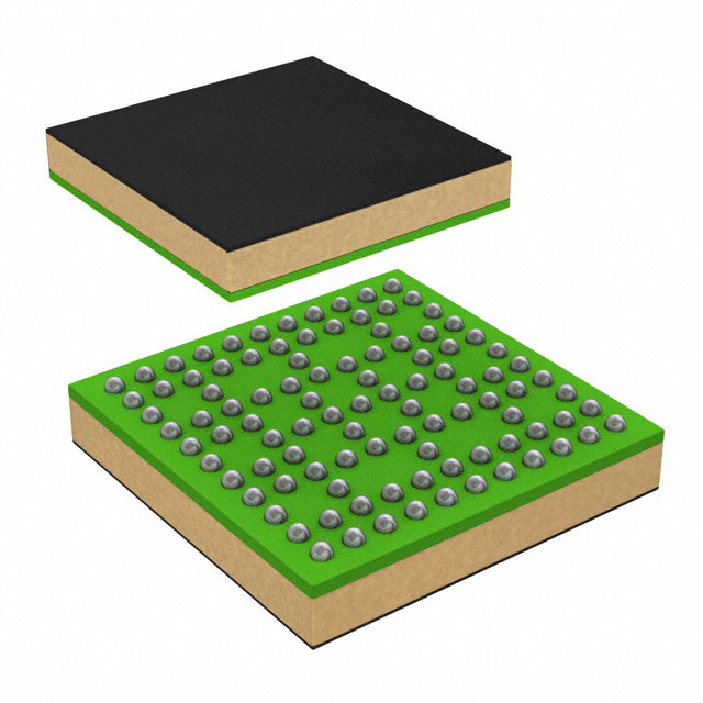
Texas Instruments DS250DF210ABMR
- Part No.:
- DS250DF210ABMR
- Manufacturer:
- Texas Instruments
- Category:
- Specialized
- Package:
- 101-TFBGA, FCCSP
- Datasheet:
-
 DS250DF210ABMR.pdf
- Description:
- IC INTFACE SPECIALIZED 101FCCSP
- Quantity:
- Payment:

- Shipping:

Inventory:2,377
Please send an inquiry. Send us your inquiry, and we will respond immediately.
Product details
Overview
DS250DF210ABMR from Texas Instruments is a dual-channel, multi-rate retimer IC designed for high-speed serial link regeneration in 100GbE, InfiniBand EDR, and OIF-CEI-25G-LR/MR/SR/VSR systems. It operates from 20.6 to 25.8 Gbps per channel with adaptive CTLE/DFE equalization, ultra-low latency (<500 ps at 25.78 Gbps), and integrated 2×2 crosspoint switching. Its single 2.5-V supply and on-chip eye monitor support front-port optical jitter cleaning and active cable assembly design.
For engineers reviewing the DS250DF210ABMR datasheet, DS250DF210ABMR pinout, DS250DF210ABMR application, or DS250DF210ABMR equivalent, key selection criteria include full-rate data lock range (20.6–25.8 Gbps), integrated CDR + FIR + CTLE + DFE signal conditioning, 6-mm × 6-mm fcBGA-101 package routing compatibility, and SMBus-configurable operation in master/slave modes.
Technical Context
The DS250DF210ABMR implements independent per-channel CDRs with PLL-based clock recovery and adaptive decision feedback equalization (DFE) across five taps, plus continuous-time linear equalization (CTLE) optimized for lossy channels up to 35+ dB at 12.9 GHz. Its low-jitter transmitter uses a 3-tap FIR filter with programmable coefficients and supports adjustable output amplitude (205–1225 mVppd).
Configuration is handled via SMBus (slave or master mode) or external EEPROM, enabling up to 16 devices on one bus using 4-level address straps (ADDR0/ADDR1). Calibration relies on a 25-MHz ±100-PPM single-ended CMOS clock (CAL_CLK_IN), with CAL_CLK_OUT supporting daisy-chained calibration across multiple devices.
Key Specifications
| Parameter | Value and Actual Design Meaning |
|---|---|
| Data Rate Range | 20.6–25.8 Gbps full-rate; supports sub-rates including 10.3125 Gbps and 12.5 Gbps for FEC pass-through |
| Latency | <500 ps typical at 25.78125 Gbps - enables real-time re-timing without system-level timing budget impact |
| Equalization | Adaptive CTLE + 5-tap DFE + 3-tap FIR transmit filter - extends reach over lossy backplanes and crosstalk-impaired interconnects |
| Output Amplitude | 205–1225 mVppd (adjustable in ~50-mV steps) - matches varying receiver sensitivity and channel loss profiles |
| Power Supply | Single 2.5 V ±5% supply - eliminates need for multiple rails and reduces decoupling complexity |
| Jitter Performance | 0.17 UIpp total jitter (TJ) at 25.78125 Gbps, 1E-12 BER - meets IEEE 802.3bj and OIF-CEI electrical compliance |
| Package | fcBGA-101, 6.0 mm × 6.0 mm, 0.5-mm pitch - enables flow-through PCB routing and thermal management on 4+ layer boards |
Pinout & Package
DS250DF210ABMR is housed in a 101-pin flip-chip ball grid array (fcBGA) package with 0.5-mm pitch and nominal body size of 6.0 mm × 6.0 mm. The package supports standard reflow profiles and requires controlled impedance routing for high-speed differential pairs.
| Pin/Terminal | Circuit Role | Design Meaning |
|---|---|---|
| RX0P / RX0N RX1P / RX1N | Differential input pairs | AC-coupled 100-Ωterminated inputs accepting 20.6–25.8 Gbps serial data; no internal ESD protection - require external AC coupling caps and layout isolation |
| TX0P / TX0N TX1P / TX1N | Differential outputs | 50-Ωdriver outputs with programmable FIR filtering and amplitude control; must be AC-coupled to downstream receivers |
| CAL_CLK_IN / CAL_CLK_OUT | Calibration clock interface | 25-MHz ±100-PPM CMOS input for VCO calibration; buffered output enables daisy-chain calibration across multiple DS250DF210ABMR devices |
| ADDR0 / ADDR1 / EN_SMB | SMBus address & mode configuration | 4-level strap pins (float/1kΩ-to-GND/20kΩ-to-GND/1kΩ-to-VDD) set unique SMBus address (16 options) and select master/slave mode |
| SDA / SDC | SMBus data/clock I/O | Open-drain 3.3-V LVCMOS pins requiring external 2–5 kΩpull-up resistors; compatible with standard SMBus timing and voltage levels |
| READ_EN_N / ALL_DONE_N | EEPROM load control/status | In SMBus master mode: READ_EN_N initiates EEPROM read; ALL_DONE_N signals completion (low = success). In slave mode: READ_EN_N serves as reset input. |
| INT_N | Interrupt output | Open-drain 3.3-V tolerant active-low interrupt pin - supports wired-OR connection with other devices for consolidated system event reporting |
Key Features
| Feature | Design Value |
|---|---|
| Integrated 2×2 crosspoint | Enables lane crossing, fanout, and multiplexing without external switches - reduces board area and insertion loss in switch fabric and optical module designs |
| On-chip Eye Opening Monitor (EOM) | Real-time eye diagram assessment without external test equipment - accelerates in-system diagnostics and link training validation |
| PRBS generator/checker | On-die pattern generation and error detection at full line rate - supports BER testing and channel characterization without host-side pattern engines |
| Adaptive equalization convergence | Automatic CTLE/DFE adaptation during CDR lock acquisition - eliminates manual tuning and ensures robust operation across temperature and voltage variation |
| Low-jitter transmitter | 0.17 UIpp total jitter at 25.78125 Gbps - satisfies stringent jitter budgets for IEEE 802.3bj 100GbE KR4 and OIF-CEI-25G-LR interfaces |
Applications
| Jitter Cleaning for Front-Port Optical Modules | Active Cable Assemblies |
|---|---|
Use Scenario: Retiming high-speed serial data exiting optical transceivers before entering ASICs or switches in top-of-rack or spine-leaf architectures. IC Role / Device Role / Timing Role: Jitter cleaner and CDR - resets accumulated jitter budget and restores signal integrity for reliable 100GbE KR4/CR4 links. Use Value: Enables use of lower-cost optical modules by compensating for transmitter jitter and fiber dispersion-induced distortion. |
Use Scenario: Signal regeneration inside high-bandwidth active copper cables used in data center rack interconnects and GPU clusters. IC Role / Device Role / Timing Role: Dual-channel retimer with adaptive equalization - extends usable cable length beyond passive limits while maintaining <10⁻¹⁵ BER. Use Value: Supports 3+ meter reach at 25.78 Gbps per lane without custom equalization firmware or host intervention. |
| Backplane and Mid-Plane Reach Extension | IEEE 802.3bj / OIF-CEI-25G Electrical Interfaces |
Use Scenario: Compensating for insertion loss, reflections, and crosstalk in multi-segment backplanes connecting line cards and fabric modules in telecom and enterprise switches. IC Role / Device Role / Timing Role: Multi-rate retimer with independent per-lane lock - handles mixed-rate traffic (e.g., 10.3125 + 25.78125 Gbps) across same physical medium. Use Value: Eliminates need for discrete equalizers and clock cleaners, reducing BOM count and improving thermal density in space-constrained chassis. |
Use Scenario: Interfacing between ASICs and pluggable modules compliant with IEEE 802.3bj 100GbE KR4, InfiniBand EDR, or OIF-CEI-25G-LR/MR/SR standards. IC Role / Device Role / Timing Role: Protocol-transparent retimer - preserves FEC, scrambling, and encoding while regenerating signal integrity. Use Value: Ensures interoperability across vendor-specific PHY implementations without modifying link-layer logic or firmware. |
Equivalent & Alternatives
The following parts are listed as comparable options for similar retimer applications.
| Alternative Part | Technical Difference | Application Difference | Selection Advice |
|---|---|---|---|
| DS250DF230ABMR | 3-channel version with identical per-channel specs, same package footprint, and extended 20.6–28.1 Gbps rate support | Required where third lane is needed (e.g., 120G QSFP28 or 3×25G switch fabric); not drop-in for 2-lane layouts | Select DS250DF230ABMR only when expanding lane count or targeting >25.8 Gbps sub-rates like 26.56 Gbps. |
| DS125DF410ABMR | Quad-channel 12.5-Gbps retimer with lower power (180 mW/channel), no DFE, and 10.3125–12.5 Gbps max rate | Suitable for legacy 100GbE SR4 or 40GbE KR4 systems but lacks 25G+ capability and adaptive DFE for long-reach channels | Choose DS125DF410ABMR for cost-sensitive, lower-speed applications where 25G+ performance and DFE are unnecessary. |
Compared with DS250DF230ABMR, DS250DF210ABMR offers optimal channel count and power efficiency for dual-lane 25G systems; versus DS125DF410ABMR, it delivers essential 25G+ rate support, DFE-based channel compensation, and tighter jitter compliance required for next-gen optical and active cable deployments.
Availability
DS250DF210ABMR is available at Aetrix Electronics and suitable for 100GbE optical module design, active cable assembly production, and high-speed backplane signal integrity enhancement requiring stable component supply and long-term lifecycle assurance.
Supply support for DS250DF210ABMR includes scheduled delivery planning, volume procurement assistance, BOM continuity management, traceable sourcing, and lifecycle availability coordination for OEM customers, industrial embedded developers, connected-device designers, and electronics production programs.
Manufacturer
Texas Instruments is a global semiconductor leader specializing in analog, embedded processing, and high-speed interface solutions, with decades of expertise in signal integrity, clocking, and data converter technologies.
The DS250DF210ABMR belongs to TI's high-speed retimer product line, engineered specifically for 25G+ serial link regeneration in cloud infrastructure, optical networking, and AI/ML accelerator interconnects where jitter, loss, and crosstalk mitigation are critical.
FAQ
What is the supported data rate range for DS250DF210ABMR?
The DS250DF210ABMR supports a continuous full-rate data range from 20.6 Gbps to 25.8 Gbps per channel, including standardized sub-rates such as 10.3125 Gbps and 12.5 Gbps. This enables FEC pass-through and compatibility with IEEE 802.3bj, InfiniBand EDR, and OIF-CEI-25G-LR/MR/SR specifications. The DS250DF210ABMR achieves lock independently on each channel without requiring external reference clocks.
Does DS250DF210ABMR require an external reference clock?
No, the DS250DF210ABMR does not require a low-jitter reference clock for CDR operation. It uses an internal PLL architecture that locks directly to the incoming data stream. A 25-MHz ±100-PPM CMOS calibration clock (CAL_CLK_IN) is required solely for VCO frequency range calibration and is not used for timing recovery. This simplifies system clock tree design and reduces board-level component count.
How is DS250DF210ABMR configured - via SMBus or EEPROM?
The DS250DF210ABMR supports both SMBus (master or slave mode) and external EEPROM configuration. SMBus mode uses ADDR0/ADDR1/EN_SMB straps to assign a unique 7-bit address and select operation mode; up to 16 devices can share one SMBus bus. EEPROM mode allows non-disruptive register loading at power-up, with Common Channel format supporting shared configuration across multiple DS250DF210ABMR devices.
What package type and pin count does DS250DF210ABMR use?
The DS250DF210ABMR is packaged in a 101-pin flip-chip BGA (fcBGA) with 0.5-mm pitch and nominal dimensions of 6.0 mm × 6.0 mm. This ABM package variant supports flow-through routing, thermal dissipation via solder balls to internal ground planes, and compatibility with standard PCB fabrication processes for high-density interconnects.
Can DS250DF210ABMR operate with 3.3-V I/Os?
The DS250DF210ABMR uses a 2.5-V core supply (VDD = 2.375–2.625 V), but its SMBus pins (SDA, SDC) and interrupt output (INT_N) are 3.3-V LVCMOS tolerant. These pins accept 3.3-V logic levels and require external 2–5 kΩpull-up resistors per SMBus specification. All high-speed differential I/Os (RX/TX) are AC-coupled and referenced to internal 2.5-V biasing - no 3.3-V signaling is applied to those lanes.
DS250DF210ABMR Specifications
- Product attributes
- Attribute value
- Manufacturer:
- Texas Instruments
- Series:
- -
- Package/Case:
- 101-TFBGA, FCCSP
- Packaging:
- Tape & Reel (TR)
- Product Status:
- Active
- Applications:
- Retimer
- Interface:
- -
- Voltage - Supply:
- -
- Supplier Device Package:
- 101-FCCSP (6x6)
- Grade:
- -
- Qualification:
- -
- Mounting Type:
- Surface Mount
DS250DF210ABMR FAQ
1.How can I place an order for DS250DF210ABMR through Aetrix?
Please submit a Request for Quotation (RFQ) for DS250DF210ABMR on Aetrix. Our sales agent will provide a competitive quotation and guide you through the order confirmation once you accept the terms.
2.Are the price and stock information for DS250DF210ABMR reliable?
The price and inventory of DS250DF210ABMR are updated periodically and may fluctuate due to market conditions. Stock and pricing data are typically refreshed every 24 hours. Quotation validity for DS250DF210ABMR is usually 5 days.
3.What payment methods are accepted for DS250DF210ABMR?
We accept Wire Transfer, PayPal, Credit Card, Western Union, MoneyGram, and Escrow for DS250DF210ABMR transactions.
Note: Certain payment methods may incur a processing fee.
4.How is shipping managed for DS250DF210ABMR?
DS250DF210ABMR orders can be shipped via leading logistics carriers, including DHL, UPS, FedEx, TNT, or Registered Mail.
Once your DS250DF210ABMR order is processed, you will receive an email with the shipment details and tracking number.
Note: Tracking information may take up to 24 hours to appear. Express delivery typically takes 3–5 business days.
5.How can I obtain technical support or documentation for DS250DF210ABMR?
For technical support, including DS250DF210ABMR datasheets, pinout diagrams, or application guidance, please contact our engineering support team. They can provide detailed documentation and assistance for your DS250DF210ABMR requirements.
6.How does Aetrix verify that DS250DF210ABMR is sourced from the original manufacturer or authorized distributors?
All DS250DF210ABMR products on Aetrix are procured from qualified distributors and authorized channels. Our dedicated quality assurance team conducts strict verification, including traceability checks and, if necessary, third-party testing. This ensures that DS250DF210ABMR meets industry standards.
7.What is the process for return or replacement of DS250DF210ABMR?
All DS250DF210ABMR units undergo pre-shipment inspection (PSI). If there is an issue with DS250DF210ABMR, returns or replacements are accepted under the following conditions:
1.Quantity discrepancies, incorrect items, or visible external defects (such as breakage or corrosion), acknowledged by Aetrix.
2.The issue is reported within 90 days of delivery.
3.The DS250DF210ABMR part is unused and in its original packaging.
Return procedure for DS250DF210ABMR:
1.Submit a request within 90 days.
2.Obtain a Return Material Authorization (RMA) from Aetrix.
DS250DF210ABMR Tags

-
NVT4857UKAZ
NXP Semiconductors

-
TCA8418RTWR
Texas Instruments

-
PCA9546APWR
Texas Instruments

-
MD0100N8-G
Microchip Technology

-
PCA9548APW,118
NXP Semiconductors

-
PCA9540BDP,118
NXP Semiconductors

-
PCA9548APWR
Texas Instruments

-
PCA9546APW,118
NXP Semiconductors

-
PTN3360DBS,518
NXP Semiconductors

-
PCA9546ABS,118
NXP Semiconductors

-
PCA9518PWR
Texas Instruments

-
PCA9545APW,118
NXP Semiconductors
Tech Hub

A practical engineering guide to 3.3V and 5V logic compatibility, input thresholds, resistor dividers, translator ICs, MOSFET level shifting, I2C pull-ups, timing limits and power-sequencing risks.

The 74HC595 uses push-pull logic outputs, while the TPIC6B595 uses 50 V open-drain DMOS sinks for higher-power loads. This guide compares timing, current limits, 3.3 V interfacing, load wiring, thermal…

The 74HC595 converts serial data into eight stable parallel outputs. This guide covers pin functions, shift and storage timing, OE and MR behavior, drive-current limits, cascading, voltage compatibilit…

A technical comparison of level-sensitive latches and edge-triggered flip-flops, covering timing windows, setup and hold limits, master–slave operation, time borrowing, race-through, HDL inference and…

A D latch stores one bit while Enable controls when data can pass. This reference covers gate-level operation, truth tables, transparency, setup and hold timing, LE versus OE, common ICs and practical …

An SR latch stores one bit through cross-coupled feedback. This engineering reference covers NOR and NAND implementations, truth tables, forbidden-state recovery, gated operation, switch debouncing, fa…

Latch circuits retain one bit through feedback. This technical reference covers SR and D latches, truth tables, transparency, timing limits, latch-versus-flip-flop behavior, applications and common log…

An engineering guide to LED driver operation, constant-current and constant-voltage outputs, linear and switching topologies, dimming, IC selection, calculations, replacement compatibility, and fault c…

Operational amplifier guide covering op amp basics, feedback, ideal vs real op amps, common configurations, buffer circuits, offset, bias current, gain-bandwidth, slew rate, rail-to-rail limits and sel…

Jumper cables guide covering safe connection order, red and black clamp placement, final ground connection, cable gauge, length, clamp quality, copper vs CCA cables, jump starter comparison and battery…


