
 My Inquiry
 My Account


Analog Devices Inc./Maxim Integrated DS28E17Q+T
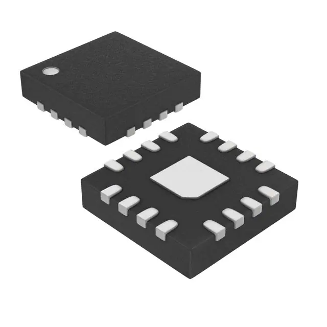
- Part No.:
- DS28E17Q+T
- Manufacturer:
- Analog Devices Inc./Maxim Integrated
- Category:
- Controllers
- Package:
- 16-WQFN Exposed Pad
- Datasheet:
-
 DS28E17Q+T.pdf
- Description:
- IC BRIDGE 1-WIRE TO I2C 16TQFN
- Quantity:
- Payment:

- Shipping:

Inventory:4,988
Please send an inquiry. Send us your inquiry, and we will respond immediately.
Product details
Overview
The DS28E17Q+T from Analog Devices is a 1-Wire-to-I2C bridge IC that enables I2C peripherals-including ADCs, DACs, display controllers, and sensors-to operate over a single-conductor 1-Wire bus. It supports standard (15kbps) and overdrive (77kbps) 1-Wire speeds, I2C clock stretching, and operates from 2.45V to 3.6V with 0.3µA sleep current. It serves as a node-level interface in distributed sensor or accessory identification systems.
For engineers reviewing the DS28E17Q+T datasheet, DS28E17Q+T pinout, DS28E17Q+T application, or DS28E17Q+T equivalent, key selection considerations include its unique 64-bit ROM ID for multidrop addressing, 100m 1-Wire reach at standard speed, support for both 100kHz and 400kHz I2C, open-drain IO pin with 2.2kΩ max pullup, and dedicated SLEEP/WAKEUP control pins for low-power system coordination.
Technical Context
The DS28E17Q+T integrates a 1-Wire physical layer controller, ROM ID engine, and full I2C bus controller in one die-enabling transparent packetized I2C data transfer via 1-Wire commands like WRITE DATA WITH STOP (4Bh) and READ DATA WITH STOP (87h). It implements automatic I2C clock stretching and supports both standard and overdrive 1-Wire timing modes.
Its architecture isolates the 1-Wire bus from I2C voltage domains: the IO pin is open-drain with programmable pullup dependency, while SDA/SCL are open-drain outputs requiring external pullups to their respective I2C bus supply. The AWAKE and BUSY pins provide real-time state feedback for host synchronization without polling.
Key Specifications
| Parameter | Value and Actual Design Meaning |
|---|---|
| 1-Wire Speed Modes | Standard (15kbps) and Overdrive (77kbps); enables longer cable runs or higher throughput based on network configuration |
| I2C Clock Support | 100kHz (standard mode) and 400kHz (fast mode); compatible with legacy and high-speed I2C peripherals |
| Supply Voltage Range | 2.45V to 3.6V; allows direct connection to common 3.3V logic rails without level shifting |
| Sleep Current | 0.3µA typical at 25°C; enables multi-year battery operation in remote sensor nodes |
| ROM ID | Factory-programmed 64-bit unique identifier (8-bit family code + 48-bit serial + 8-bit CRC); guarantees collision-free addressing in multidrop 1-Wire networks |
| 1-Wire Pullup Max | 2.2kΩ; defines minimum pullup strength required for reliable signal recovery across temperature and capacitance |
| Operating Temp | -40°C to +85°C; qualified for industrial and automotive under-hood accessory applications |
Pinout & Package
DS28E17Q+T uses a 4mm × 4mm × 0.75mm 16-pin TQFN package with exposed pad (EP), rated for -40°C to +85°C operation and θJA = 40°C/W.
| Pin/Terminal | Circuit Role | Design Meaning |
|---|---|---|
| IO | 1-Wire bidirectional bus interface | Open-drain pin requiring external pullup; carries all 1-Wire communication including reset, presence detect, and data packets |
| RESET | Active-low reset input/output | Bidirectional: accepts external reset pulses or asserts internal reset during power-up/fail; no external RC needed |
| WAKEUP | Edge-triggered wake input | Rising-edge sensitive only during sleep mode; enables precise, low-latency wake from µA sleep |
| SLEEP | Edge-triggered sleep input | Falling-edge sensitive; initiates hardware sleep without software command overhead |
| AWAKE | Push-pull status output | Drives high when active, low when asleep; can directly control power states of companion devices (e.g., sensors) |
| BUSY | Push-pull transaction indicator | Asserts low after CRC validation and remains low until I2C transaction completes; blocks further 1-Wire commands during execution |
| ED | Push-pull error flag | Drives low on invalid command, bad CRC16, or I2C NACK; resets only on 1-Wire reset command |
| XD | Push-pull packet-reception indicator | Drives low upon receipt of Device command and stays low until full packet (including CRC16) is received |
| VDD | Digital supply | 2.45V–3.6V input; powers core logic and I/O drivers; must be stable before 1-Wire activity |
| REG18 | Internal 1.8V regulator output | Provides 1.72V ±0.1V regulated supply; requires 1µF capacitor; supports light loads (<200µA) |
| GND | Digital ground reference | Common return for VDD, IO, and I2C signals; must be connected to EP for thermal performance |
| SCL | I2C clock output | Open-drain output; requires external pullup to I2C bus VCC; generates clock for attached I2C peripheral |
| SDA | I2C data I/O | Open-drain bidirectional pin; shares bus with peripheral; requires external pullup to I2C bus VCC |
| N.C. | No connection | Pins 9, 10, 11 are unconnected; must remain floating or tied to GND per layout guidelines |
| EP | Exposed thermal pad | Must be soldered to GND plane for thermal dissipation and EMI reduction; improves θJA by ~10°C/W |
Key Features
| Feature | Design Value |
|---|---|
| 1-Wire-to-I2C protocol translation | Enables I2C peripherals to be controlled over single-wire infrastructure-eliminating need for separate I2C routing in space-constrained or long-cable designs |
| 100-meter 1-Wire reach (typ) | Extends I2C functionality beyond PCB boundaries into enclosures, chassis, or remote modules using standard twisted-pair wiring |
| Dedicated SLEEP/WAKEUP pins | Supports deterministic, sub-µs wake latency and zero-software-overhead sleep entry-critical for energy harvesting and battery-powered accessories |
| Hardware BUSY/ED/XD signaling | Offloads host microcontroller from polling and CRC checking; enables interrupt-driven, event-synchronized firmware architecture |
| Factory-programmed 64-bit ROM ID | Provides immutable device identity for secure accessory authentication, calibration data binding, and firmware version tracking without external memory |
| Integrated 1.8V regulator (REG18) | Reduces BOM count by powering internal logic and optional low-voltage peripherals-no external LDO required for core operation |
Applications
| Accessory Identification and Control | I2C Sensors |
|---|---|
Use Scenario: Authenticating and configuring third-party printer cartridges, camera lenses, or medical probes plugged into host equipment. IC Role / Device Role / Timing Role: Acts as secure, addressable bridge between host 1-Wire controller and I2C EEPROM/sensor inside accessory-handling ROM ID verification and encrypted command forwarding. Use Value: Enables plug-and-play accessory compatibility with tamper-resistant identification using factory ROM ID and command-level CRC protection. | Use Scenario: Deploying temperature, humidity, or gas sensors in HVAC ducts, industrial cabinets, or outdoor enclosures up to 100 meters from controller. IC Role / Device Role / Timing Role: Translates host 1-Wire commands into timed I2C reads/writes for local sensor ICs-managing clock stretching and ACK/NACK handshaking transparently. Use Value: Eliminates need for I2C repeaters or level shifters; extends sensing range while maintaining I2C timing compliance and noise immunity. |
| Display Controllers | ADCs/DACs |
Use Scenario: Driving segmented or OLED displays in kiosks, point-of-sale terminals, or industrial HMIs where display modules are remotely mounted. IC Role / Device Role / Timing Role: Bridges host MCU's 1-Wire interface to I2C display driver IC-buffering display data packets and managing frame sync via BUSY pin assertion. Use Value: Reduces interconnect complexity from 4+ wires (I2C + power) to 2-wire (1-Wire + GND), simplifying cable harnesses and connector footprints. | Use Scenario: Acquiring analog signals from remote transducers (e.g., strain gauges, thermocouples) or generating precision analog outputs in test equipment. IC Role / Device Role / Timing Role: Provides isolated, addressable access to I2C ADC/DAC ICs-supporting burst conversions and register-based configuration over long 1-Wire links. Use Value: Maintains 12–16-bit measurement integrity by avoiding signal degradation over long traces; enables centralized calibration storage in host EEPROM. |
Equivalent & Alternatives
The following parts are listed as comparable options for similar 1-Wire-to-I2C bridge applications.
| Alternative Part | Technical Difference | Application Difference | Selection Advice |
|---|---|---|---|
| MAX31826ATM+ | Integrated ±2°C temperature sensor + 1-Wire interface; no I2C bridging capability; fixed sensor function only | Only suitable for standalone temperature monitoring-not for general-purpose I2C peripheral interfacing | Select only if application requires embedded temp sensing without external I2C devices |
| DS28E05Q+T | 1-Wire EEPROM (1KB) with GPIO; lacks I2C controller, clock stretching, or packetized I2C translation logic | Used for secure data storage and simple I/O expansion-not for bridging to external I2C peripherals | Choose only for authenticated memory/log storage where no I2C device control is needed |
Compared with MAX31826ATM+ and DS28E05Q+T, the DS28E17Q+T uniquely delivers full bidirectional I2C protocol translation with hardware timing control, making it the sole option among these three for connecting arbitrary I2C peripherals (ADCs, DACs, displays) to a 1-Wire host.
Availability
DS28E17Q+T is available at Aetrix Electronics and suitable for industrial sensor networks, secure accessory identification systems, and remote display interfaces requiring stable component supply, long-term lifecycle support, and guaranteed traceable sourcing.
Supply support for DS28E17Q+T includes scheduled delivery planning, volume procurement assistance, BOM continuity management, traceable sourcing, and lifecycle availability coordination for OEM customers, industrial embedded developers, connected-device designers, and electronics production programs.
Manufacturer
Analog Devices, Inc. is a global semiconductor leader specializing in high-performance analog, mixed-signal, and digital signal processing technologies for precision instrumentation, industrial automation, and communications.
The DS28E17Q+T belongs to Analog Devices' secure connectivity product line, designed specifically to extend trusted, low-pin-count interfaces-like 1-Wire-into complex I2C-based subsystems while preserving device identity and data integrity.
FAQ
What is the primary function of the DS28E17Q+T?
The DS28E17Q+T is a dedicated 1-Wire-to-I2C bridge IC that enables standard and fast-mode I2C peripherals (e.g., sensors, ADCs, display controllers) to be controlled over a single-conductor 1-Wire bus. It handles full protocol translation-including ROM ID addressing, packetized I2C command framing, clock stretching, and CRC validation-without requiring host firmware to manage low-level timing.
Does the DS28E17Q+T support both standard and overdrive 1-Wire speeds?
Yes, the DS28E17Q+T supports two 1-Wire communication speeds: standard mode (up to 15kbps) and overdrive mode (up to 77kbps). Mode selection is controlled via 1-Wire ROM commands (e.g., Overdrive-Skip ROM or Overdrive-Match ROM). The device automatically switches timing parameters upon entering overdrive mode, and returns to standard speed after a 480µs reset pulse.
How does the DS28E17Q+T handle I2C clock stretching?
The DS28E17Q+T fully supports I2C clock stretching: when an attached I2C peripheral holds SCL low to delay transmission, the DS28E17Q+T detects this condition and pauses 1-Wire response generation until the I2C transaction completes. This ensures timing-compliant interoperability with any I2C device that uses clock stretching for flow control or internal processing.
Can multiple DS28E17Q+T devices coexist on the same 1-Wire bus?
Yes, multiple DS28E17Q+T devices can coexist on a single 1-Wire bus. Each DS28E17Q+T has a factory-programmed, globally unique 64-bit ROM ID used for individual addressing via Match ROM or Search ROM commands. The 1-Wire protocol ensures that only the targeted DS28E17Q+T responds to subsequent Device commands, enabling true multidrop operation without contention.
What is the role of the AWAKE and BUSY pins on the DS28E17Q+T?
The AWAKE pin is a push-pull output indicating operational state (high = awake, low = asleep), useful for synchronizing companion devices. The BUSY pin is also push-pull and drives low after successful CRC validation of a 1-Wire packet, remaining low until the entire I2C transaction finishes-blocking further 1-Wire commands and enabling interrupt-driven host coordination without polling. Both pins are integral to deterministic low-power system design using the DS28E17Q+T.
DS28E17Q+T Specifications
- Product attributes
- Attribute value
- Manufacturer:
- Analog Devices Inc./Maxim Integrated
- Package/Case:
- 16-WQFN Exposed Pad
- Programmable:
- Not Verified
- Protocol:
- 1-Wire®
- Function:
- Bridge, 1-Wire® to I2C
- Interface:
- I2C
- Standards:
- -
- Voltage - Supply:
- 2.45V ~ 3.6V
- Current - Supply:
- 2.6mA
- Operating Temperature:
- -40°C ~ 85°C
- Supplier Device Package:
- 16-TQFN (4x4)
- Grade:
- -
- Qualification:
- -
DS28E17Q+T FAQ
1.How can I place an order for DS28E17Q+T through Aetrix?
Please submit a Request for Quotation (RFQ) for DS28E17Q+T on Aetrix. Our sales agent will provide a competitive quotation and guide you through the order confirmation once you accept the terms.
2.Are the price and stock information for DS28E17Q+T reliable?
The price and inventory of DS28E17Q+T are updated periodically and may fluctuate due to market conditions. Stock and pricing data are typically refreshed every 24 hours. Quotation validity for DS28E17Q+T is usually 5 days.
3.What payment methods are accepted for DS28E17Q+T?
We accept Wire Transfer, PayPal, Credit Card, Western Union, MoneyGram, and Escrow for DS28E17Q+T transactions.
Note: Certain payment methods may incur a processing fee.
4.How is shipping managed for DS28E17Q+T?
DS28E17Q+T orders can be shipped via leading logistics carriers, including DHL, UPS, FedEx, TNT, or Registered Mail.
Once your DS28E17Q+T order is processed, you will receive an email with the shipment details and tracking number.
Note: Tracking information may take up to 24 hours to appear. Express delivery typically takes 3–5 business days.
5.How can I obtain technical support or documentation for DS28E17Q+T?
For technical support, including DS28E17Q+T datasheets, pinout diagrams, or application guidance, please contact our engineering support team. They can provide detailed documentation and assistance for your DS28E17Q+T requirements.
6.How does Aetrix verify that DS28E17Q+T is sourced from the original manufacturer or authorized distributors?
All DS28E17Q+T products on Aetrix are procured from qualified distributors and authorized channels. Our dedicated quality assurance team conducts strict verification, including traceability checks and, if necessary, third-party testing. This ensures that DS28E17Q+T meets industry standards.
7.What is the process for return or replacement of DS28E17Q+T?
All DS28E17Q+T units undergo pre-shipment inspection (PSI). If there is an issue with DS28E17Q+T, returns or replacements are accepted under the following conditions:
1.Quantity discrepancies, incorrect items, or visible external defects (such as breakage or corrosion), acknowledged by Aetrix.
2.The issue is reported within 90 days of delivery.
3.The DS28E17Q+T part is unused and in its original packaging.
Return procedure for DS28E17Q+T:
1.Submit a request within 90 days.
2.Obtain a Return Material Authorization (RMA) from Aetrix.
DS28E17Q+T Tags

-
PTN5150AHXMP
NXP Semiconductors

-
USB3740B-AI9-TR
Microchip Technology

-
USB3740B-AI2-TR
Microchip Technology

-
USB3300-EZK-TR
Microchip Technology
-
USB3300-EZK
Microchip Technology

-
FUSB340TMX
onsemi

-
FUSB302BMPX
onsemi

-
DP83826IRHBR
Texas Instruments

-
MCP2518FDT-E/QBB
Microchip Technology
-
FUSB302MPX
onsemi

-
MCP2518FDT-E/SL
Microchip Technology

-
FT260Q-R
FTDI, Future Technology Devices International Ltd
Tech Hub

A practical engineering guide to 3.3V and 5V logic compatibility, input thresholds, resistor dividers, translator ICs, MOSFET level shifting, I2C pull-ups, timing limits and power-sequencing risks.

The 74HC595 uses push-pull logic outputs, while the TPIC6B595 uses 50 V open-drain DMOS sinks for higher-power loads. This guide compares timing, current limits, 3.3 V interfacing, load wiring, thermal…

The 74HC595 converts serial data into eight stable parallel outputs. This guide covers pin functions, shift and storage timing, OE and MR behavior, drive-current limits, cascading, voltage compatibilit…

A technical comparison of level-sensitive latches and edge-triggered flip-flops, covering timing windows, setup and hold limits, master–slave operation, time borrowing, race-through, HDL inference and…

A D latch stores one bit while Enable controls when data can pass. This reference covers gate-level operation, truth tables, transparency, setup and hold timing, LE versus OE, common ICs and practical …

An SR latch stores one bit through cross-coupled feedback. This engineering reference covers NOR and NAND implementations, truth tables, forbidden-state recovery, gated operation, switch debouncing, fa…

Latch circuits retain one bit through feedback. This technical reference covers SR and D latches, truth tables, transparency, timing limits, latch-versus-flip-flop behavior, applications and common log…

An engineering guide to LED driver operation, constant-current and constant-voltage outputs, linear and switching topologies, dimming, IC selection, calculations, replacement compatibility, and fault c…

Operational amplifier guide covering op amp basics, feedback, ideal vs real op amps, common configurations, buffer circuits, offset, bias current, gain-bandwidth, slew rate, rail-to-rail limits and sel…

Jumper cables guide covering safe connection order, red and black clamp placement, final ground connection, cable gauge, length, clamp quality, copper vs CCA cables, jump starter comparison and battery…


