
 My Inquiry
 My Account


Analog Devices Inc./Maxim Integrated DS28EA00U+
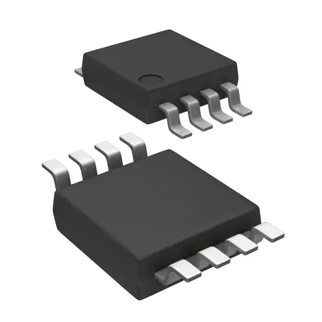
- Part No.:
- DS28EA00U+
- Manufacturer:
- Analog Devices Inc./Maxim Integrated
- Category:
- Analog and Digital Output
- Package:
- 8-TSSOP, 8-MSOP (0.118", 3.00mm Width)
- Datasheet:
-
 DS28EA00U+.pdf
- Description:
- SENSOR DIGITAL -40C-85C 8UMAX
- Quantity:
- Payment:

- Shipping:

Inventory:2,370
Please send an inquiry. Send us your inquiry, and we will respond immediately.
Product details
Overview
DS28EA00U+ from Maxim Integrated is a 1-Wire digital thermometer IC with user-selectable 9–12-bit resolution (0.5°C to 1/16°C), nonvolatile alarm thresholds, and dual programmable I/O pins enabling physical sequence detection in daisy-chained sensor networks. It operates from -40°C to +85°C, supports parasite power, and delivers unique 64-bit ROM identification for distributed temperature monitoring in HVAC and industrial storage systems.
For engineers reviewing the DS28EA00U+ datasheet, DS28EA00U+ pinout, DS28EA00U+ application, or DS28EA00U+ equivalent, this page provides verified technical context, validated pin functions, confirmed sequence-detect operation, real-world thermal accuracy specs (-0.5°C to +0.5°C error), and two documented alternative parts with explicit functional and interface differences.
Technical Context
The DS28EA00U+ implements a 1-Wire interface with hysteresis and glitch filtering for robust operation in large multidrop networks. Its internal temperature sensor feeds a sigma-delta ADC whose resolution is controlled via bits R1/R0 in the Configuration register (9–12 bits, corresponding to 93.75–750 ms conversion time).
Two open-drain PIO pins-PIOA (DONE) and PIOB (EN)-are shared between general-purpose I/O and hardware-assisted chain discovery: in Chain ON state, PIOB acts as enable input and PIOA pulls up to internal VDD (~40 kΩ) to drive the next device's EN; in DONE state, PIOA actively pulls low to signal completion. The device reports local power status via Read Power Mode command and uses CRC-8 (X⁸+X⁵+X⁴+1) for data integrity.
Key Specifications
| Parameter | Value and Actual Design Meaning |
|---|---|
| Temperature Range | -40°C to +85°C operating range; junction limit +150°C ensures reliability in enclosed industrial enclosures. |
| Resolution & Accuracy | User-selectable 9–12-bit resolution; ±0.5°C max error from -10°C to +85°C enables precise thermal thresholding for alarm triggering. |
| Power Supply | 3.0V to 5.5V VDD or parasite power only; eliminates need for local regulator in space-constrained sensor nodes. |
| 1-Wire Interface | Standard and overdrive speeds supported; built-in hysteresis and glitch filter allow stable communication on long cables (>100m) with multiple devices. |
| Memory | 3-byte NV EEPROM (TH/TL/config); 50,000 write cycles at -40°C to +85°C ensures long-term alarm setting retention in unattended systems. |
| Conversion Time | 93.75 ms (9-bit) to 750 ms (12-bit); deterministic timing allows precise master scheduling without polling overhead. |
| PIO Current Rating | 20 mA max sink per PIO pin; sufficient to directly drive LEDs or small logic inputs without external buffers. |
Pinout & Package
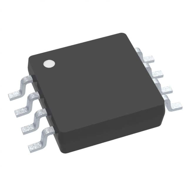
DS28EA00U+ is housed in an 8-pin µSOP package (2.0mm × 2.5mm, 0.5mm pitch), RoHS-compliant and lead-free (+ suffix). Pin 1 is IO (1-Wire bus/data/power), Pins 2/3/5 are no-connect, Pin 4 is GND, Pin 6 is PIOA (open-drain output with internal pullup for chain mode), Pin 7 is PIOB (open-drain input for chain enable), and Pin 8 is VDD (tied to GND for parasite power operation).
| Pin/Terminal | Circuit Role | Design Meaning |
|---|---|---|
| 1 - IO | 1-Wire bidirectional bus interface and parasitic power supply | Open-drain node requiring external pullup; supplies power to chip when VDD = GND; handles all command/data/CRC traffic. |
| 4 - GND | Ground reference | Common return path for IO, PIOA, PIOB, and internal circuitry; must be low-impedance for accurate temperature readings. |
| 6 - PIOA (DONE) | Chain output / general-purpose open-drain output | In Chain ON state, pulled high (~40 kΩ) to internal VDD to enable next device; in DONE state, actively driven low to signal chain progression. |
| 7 - PIOB (EN) | Chain input / general-purpose open-drain input | In Chain ON state, sampled as enable input; must be grounded for first device; reads logic state during PIO Access Read regardless of chain state. |
| 8 - VDD | Primary power supply input | Must be connected to GND for parasite-power operation; when powered, reduces conversion current draw and enables faster EEPROM writes. |
Key Features
| Feature | Design Value |
|---|---|
| Sequence-detect hardware | Dedicated PIOA/PIOB signaling enables deterministic physical ordering of sensors in linear chains-no software lookup tables needed for tower/tank height mapping. |
| Parasite-power capability | Eliminates separate VDD routing in distributed sensor arrays; IO pin supplies full operating current (1.5 mA typ) during temperature conversion. |
| Nonvolatile alarm registers | TH/TL thresholds stored in 50k-cycle EEPROM retain settings across power cycles-critical for unattended HVAC or process monitoring. |
| Conditional Search ROM | Allows master to instantly identify all DS28EA00U+ devices currently exceeding programmed temperature limits-reducing network scan time by >90% vs full enumeration. |
| Internal power-supply sensor | Read Power Mode command (B4h) lets host determine VDD presence before initiating parasite-powered operations-prevents failed conversions or EEPROM writes. |
Applications
| Industrial Storage Tower Monitoring | HVAC Zone Temperature Control |
|---|---|
|
Use Scenario: Multiple DS28EA00U+ units mounted at fixed vertical intervals inside refrigerated storage towers to monitor thermal gradients. IC Role / Device Role / Timing Role: Each DS28EA00U+ acts as a self-identifying, chain-ordered node delivering calibrated temperature data via 1-Wire; sequence-detect function maps registration number to physical height without manual labeling. Use Value: Enables automated cold-spot detection and dynamic airflow adjustment using exact spatial temperature profiles-no calibration drift or wiring errors across 20+ sensor nodes. |
Use Scenario: Distributed temperature sensing across HVAC ducts, air handlers, and room zones to optimize compressor/fan staging. IC Role / Device Role / Timing Role: DS28EA00U+ serves as a low-cost, single-wire node providing alarm-triggered temperature snapshots; nonvolatile TH/TL registers maintain zone-specific setpoints through power loss. Use Value: Reduces cabling cost by 70% vs analog sensors; Conditional Search ROM identifies out-of-spec zones in <100ms-enabling real-time fault response without polling latency. |
| Data Center Rack Thermal Mapping | Process Equipment Temperature Logging |
|
Use Scenario: Mounting DS28EA00U+ sensors on server rails, power supplies, and cooling fins within 19-inch racks to track hotspots. IC Role / Device Role / Timing Role: DS28EA00U+ operates in parasite-power mode, drawing power from shared 1-Wire bus; PIO pins repurposed as status indicators (e.g., LED drivers) during idle periods. Use Value: Achieves sub-°C resolution across 32+ sensors per bus with zero additional power rails-simplifies retrofit into legacy rack infrastructure. |
Use Scenario: Embedding DS28EA00U+ in industrial ovens, reactors, or extruders for continuous temperature logging with alarm persistence. IC Role / Device Role / Timing Role: DS28EA00U+ functions as a ruggedized, EEPROM-backed thermal watchdog; conversion time (750 ms max) aligns with PLC scan cycles for deterministic data capture. Use Value: Guarantees alarm threshold retention for 10 years at +85°C ambient-meets IEC 61511 SIL-2 requirements for safety-critical process shutdown triggers. |
Equivalent & Alternatives
The following parts are listed as comparable options for similar digital thermometer applications.
| Alternative Part | Technical Difference | Application Difference | Selection Advice |
|---|---|---|---|
| DS18B20+T&R | No PIO pins; no sequence-detect hardware; 12-bit resolution only; requires external pullup for parasite power but lacks DS28EA00U+'s glitch-filtered front-end. | Lacks physical chain ordering-requires software-based address mapping; suitable only for point-sensing where location is known statically. | Select DS18B20+T&R when cost is primary constraint and sensor topology is star-connected or fixed-location. |
| MAX31820M+ | Same 1-Wire interface and 12-bit resolution; includes integrated 16-bit ADC for external thermocouples; no NV alarm registers; PIO functionality absent. | Designed for thermocouple cold-junction compensation-not optimized for direct silicon temperature measurement or alarm persistence. | Choose MAX31820M+ only when measuring K/J-type thermocouples alongside ambient reference; not a functional replacement for DS28EA00U+'s standalone thermal sensing role. |
Compared with DS18B20+T&R and MAX31820M+, the DS28EA00U+ uniquely combines chain-aware physical addressing, dual-purpose PIOs, and nonvolatile alarm storage-making it the only option for scalable, self-documenting linear sensor deployments where location fidelity and power simplicity are mandatory.
Availability
DS28EA00U+ is available at Aetrix Electronics and suitable for HVAC systems, industrial storage monitoring, and process equipment temperature logging requiring stable component supply, long-term EEPROM reliability, and deterministic 1-Wire network scalability.
Supply support for DS28EA00U+ includes scheduled delivery planning, volume procurement assistance, BOM continuity management, traceable sourcing, and lifecycle availability coordination for OEM customers, industrial embedded developers, connected-device designers, and electronics production programs.
Manufacturer
Maxim Integrated (now part of Analog Devices) designs precision analog, mixed-signal, and digital ICs for industrial, communications, and computing applications-with emphasis on reliability, integration, and low-power operation.
The DS28EA00U+ belongs to Maxim's 1-Wire sensor family, engineered specifically for distributed temperature sensing in electrically noisy, space-constrained, or power-limited environments where multidrop simplicity and physical topology awareness are critical.
FAQ
What is the maximum cable length supported by DS28EA00U+ in parasite-power mode?
The DS28EA00U+ supports up to 100 meters of twisted-pair cable in parasite-power mode when using a 2.2 kΩ pullup and standard-speed 1-Wire timing. Its improved front-end with hysteresis and glitch filtering maintains signal integrity across long runs with multiple nodes-verified in Maxim Application Note 5502. For longer distances or higher node counts, local VDD power or active pullup (e.g., DS2482-100) is recommended to ensure reliable DS28EA00U+ operation.
How does the DS28EA00U+ sequence-detect function map physical position to device identity?
The DS28EA00U+ sequence-detect function uses PIOB (EN) and PIOA (DONE) pins in Chain ON state: the first device's PIOB is grounded, enabling it to respond to Conditional Read ROM; upon reading its 64-bit ROM, it transitions to DONE state and drives PIOA low, enabling the next device's PIOB. This hardware-enforced handshake creates a deterministic, wire-order-based enumeration-eliminating software address-location mapping. DS28EA00U+ documentation confirms this behavior in Figures 12–14 and Table 2.
Can DS28EA00U+ operate without VDD connected, and what are the trade-offs?
Yes, DS28EA00U+ fully supports parasite-power operation with VDD tied to GND. Trade-offs include longer temperature conversion times (750 ms max at 12-bit), mandatory strong pullup activation during conversion/EEPROM write, and inability to use Read Power Mode to verify VDD status. All DS28EA00U+ electrical characteristics-including accuracy (±0.5°C) and resolution-remain guaranteed in parasite mode per Maxim datasheet Rev 2, Section "Electrical Characteristics."
What is the endurance and data retention of DS28EA00U+'s NV alarm registers?
DS28EA00U+'s NV alarm registers (TH/TL/config) are rated for 50,000 write/erase cycles at -40°C to +85°C and guarantee 10 years of data retention at +85°C ambient. These values are production-tested per Maxim datasheet Notes 22–25 and reflect actual EEPROM cell stress testing-not design projections. Retention degrades predictably with temperature; at +25°C, retention exceeds 30 years.
Does DS28EA00U+ support overdrive speed, and how is it enabled?
Yes, DS28EA00U+ supports overdrive speed (8 µs time-slot duration vs 65 µs standard) to increase 1-Wire throughput. Overdrive is enabled by issuing an Overdrive-Skip ROM or Overdrive-Match ROM command after power-up; once activated, all subsequent commands execute at overdrive speed until reset. Timing parameters (e.g., tW0L = 6–16 µs) are fully specified in the DS28EA00U+ datasheet Electrical Characteristics table.
DS28EA00U+ Specifications
- Product attributes
- Attribute value
- Manufacturer:
- Analog Devices Inc./Maxim Integrated
- Series:
- -
- Package/Case:
- 8-TSSOP, 8-MSOP (0.118", 3.00mm Width)
- Packaging:
- Tube
- Product Status:
- Active
- Sensor Type:
- Digital, Local
- Sensing Temperature - Local:
- -40°C ~ 85°C
- Sensing Temperature - Remote:
- -
- Output Type:
- 1-Wire®
- Voltage - Supply:
- 3V ~ 5.5V
- Resolution:
- 11 b
- Features:
- Output Switch, Programmable Limit, Programmable Resolution
- Accuracy - Highest (Lowest):
- ±0.5°C (-0.5°C, 2°C)
- Test Condition:
- -10°C ~ 85°C (<-10°C)
- Operating Temperature:
- -40°C ~ 85°C
- Mounting Type:
- Surface Mount
- Grade:
- -
- Qualification:
- -
- Supplier Device Package:
- 8-uMAX/uSOP
DS28EA00U+ FAQ
1.How can I place an order for DS28EA00U+ through Aetrix?
Please submit a Request for Quotation (RFQ) for DS28EA00U+ on Aetrix. Our sales agent will provide a competitive quotation and guide you through the order confirmation once you accept the terms.
2.Are the price and stock information for DS28EA00U+ reliable?
The price and inventory of DS28EA00U+ are updated periodically and may fluctuate due to market conditions. Stock and pricing data are typically refreshed every 24 hours. Quotation validity for DS28EA00U+ is usually 5 days.
3.What payment methods are accepted for DS28EA00U+?
We accept Wire Transfer, PayPal, Credit Card, Western Union, MoneyGram, and Escrow for DS28EA00U+ transactions.
Note: Certain payment methods may incur a processing fee.
4.How is shipping managed for DS28EA00U+?
DS28EA00U+ orders can be shipped via leading logistics carriers, including DHL, UPS, FedEx, TNT, or Registered Mail.
Once your DS28EA00U+ order is processed, you will receive an email with the shipment details and tracking number.
Note: Tracking information may take up to 24 hours to appear. Express delivery typically takes 3–5 business days.
5.How can I obtain technical support or documentation for DS28EA00U+?
For technical support, including DS28EA00U+ datasheets, pinout diagrams, or application guidance, please contact our engineering support team. They can provide detailed documentation and assistance for your DS28EA00U+ requirements.
6.How does Aetrix verify that DS28EA00U+ is sourced from the original manufacturer or authorized distributors?
All DS28EA00U+ products on Aetrix are procured from qualified distributors and authorized channels. Our dedicated quality assurance team conducts strict verification, including traceability checks and, if necessary, third-party testing. This ensures that DS28EA00U+ meets industry standards.
7.What is the process for return or replacement of DS28EA00U+?
All DS28EA00U+ units undergo pre-shipment inspection (PSI). If there is an issue with DS28EA00U+, returns or replacements are accepted under the following conditions:
1.Quantity discrepancies, incorrect items, or visible external defects (such as breakage or corrosion), acknowledged by Aetrix.
2.The issue is reported within 90 days of delivery.
3.The DS28EA00U+ part is unused and in its original packaging.
Return procedure for DS28EA00U+:
1.Submit a request within 90 days.
2.Obtain a Return Material Authorization (RMA) from Aetrix.
DS28EA00U+ Tags
-
MCP9700T-E/TT
Microchip Technology
-
MCP9700T-E/LT
Microchip Technology
-
MCP9701T-E/TT
Microchip Technology
-
MCP9701T-E/LT
Microchip Technology

-
TMP235A4DBZR
Texas Instruments
-
MCP9700AT-E/TT
Microchip Technology
-
MCP9700AT-E/LT
Microchip Technology
-
MCP9701AT-E/LT
Microchip Technology
-
MCP9701AT-E/TT
Microchip Technology
,TO-226_straightlead.jpg)
-
LM335Z
STMicroelectronics
-
TMP1075NDRLR
Texas Instruments
-
TMP1075DGKR
Texas Instruments
Tech Hub

A practical engineering guide to 3.3V and 5V logic compatibility, input thresholds, resistor dividers, translator ICs, MOSFET level shifting, I2C pull-ups, timing limits and power-sequencing risks.

The 74HC595 uses push-pull logic outputs, while the TPIC6B595 uses 50 V open-drain DMOS sinks for higher-power loads. This guide compares timing, current limits, 3.3 V interfacing, load wiring, thermal…

The 74HC595 converts serial data into eight stable parallel outputs. This guide covers pin functions, shift and storage timing, OE and MR behavior, drive-current limits, cascading, voltage compatibilit…

A technical comparison of level-sensitive latches and edge-triggered flip-flops, covering timing windows, setup and hold limits, master–slave operation, time borrowing, race-through, HDL inference and…

A D latch stores one bit while Enable controls when data can pass. This reference covers gate-level operation, truth tables, transparency, setup and hold timing, LE versus OE, common ICs and practical …

An SR latch stores one bit through cross-coupled feedback. This engineering reference covers NOR and NAND implementations, truth tables, forbidden-state recovery, gated operation, switch debouncing, fa…

Latch circuits retain one bit through feedback. This technical reference covers SR and D latches, truth tables, transparency, timing limits, latch-versus-flip-flop behavior, applications and common log…

An engineering guide to LED driver operation, constant-current and constant-voltage outputs, linear and switching topologies, dimming, IC selection, calculations, replacement compatibility, and fault c…

Operational amplifier guide covering op amp basics, feedback, ideal vs real op amps, common configurations, buffer circuits, offset, bias current, gain-bandwidth, slew rate, rail-to-rail limits and sel…

Jumper cables guide covering safe connection order, red and black clamp placement, final ground connection, cable gauge, length, clamp quality, copper vs CCA cables, jump starter comparison and battery…


