
 My Inquiry
 My Account


Analog Devices Inc./Maxim Integrated DS3514T+
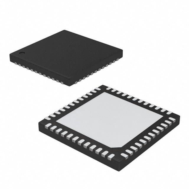
- Part No.:
- DS3514T+
- Manufacturer:
- Analog Devices Inc./Maxim Integrated
- Category:
- Video Amps and Modules
- Package:
- 48-WFQFN Exposed Pad
- Datasheet:
-
 DS3514T+.pdf
- Description:
- IC AMP TFT-LCD 48TQFN
- Quantity:
- Payment:

- Shipping:

Inventory:233
Please send an inquiry. Send us your inquiry, and we will respond immediately.
Product details
Overview
DS3514T+ from Maxim Integrated is a programmable I²C gamma and VCOM buffer IC with on-chip EEPROM, designed for TFT-LCD panel biasing. It integrates 14 × 10-bit gamma DACs (GM1–GM14), one 8-bit VCOM DAC, rail-to-rail buffer amplifiers, and four independent EEPROM banks per channel. It operates from 9.0V to 15.0V analog supply and 2.7V to 5.5V digital supply, delivering 250mA peak VCOM drive current and sub-5μs gamma settling time - enabling real-time display calibration in industrial and automotive LCD systems.
For engineers reviewing the DS3514T+ datasheet, DS3514T+ pinout, DS3514T+ application, or DS3514T+ equivalent, key selection considerations include its dual-mode control (S0/S1 pin-selectable EEPROM banks vs. I²C individual-channel update), 48-pin TQFN package with exposed pad, 400kHz I²C interface compliance, and factory-default S0/S1 bank-updating mode supporting temperature-compensated gamma tables and backlight dimming algorithms.
Technical Context
The DS3514T+ implements three configurable operating modes via Control Register bits CR.1 and CR.0: S0/S1 pin-controlled bank selection (factory default), SOFT S0/S1 bit-controlled bank selection (I²C-written), and I²C individual-channel Latch A update mode. Each gamma channel has four 10-bit EEPROM words; the VCOM channel has four 8-bit EEPROM words - enabling storage of multiple gamma/VCOM profiles for adaptive display tuning.
Its architecture features dual independently loaded data latches (Latch A and Latch B) per channel, asynchronous DAC updates via LD pin edge transitions, and high-current VCOM output optimized for fast settling (<2.0μs to 0.1%) into 1μF capacitive loads. The device supports power-on recall from EEPROM based on S0/S1 state or fixed address, and includes thermal shutdown at +150°C junction temperature.
Key Specifications
| Parameter | Value and Actual Design Meaning |
|---|---|
| DAC Resolution | 14 × 10-bit gamma outputs (GM1–GM14); 1 × 8-bit VCOM output |
| Analog Supply Range | 9.0V to 15.0V - supports wide TFT-LCD panel voltage rails |
| Digital Supply Range | 2.7V to 5.5V - compatible with standard microcontroller I²C interfaces |
| I²C Speed Support | Up to 400kHz fast-mode - enables rapid profile switching and field calibration |
| VCOM Output Drive | 250mA peak current - sufficient to drive large-area TFT-LCD VCOM nodes |
| Gamma Settling Time | 5.0μs (to 4tAU with ±20mA load) - ensures stable pixel bias during dynamic content |
| EEPROM Endurance | 200,000 write cycles at +25°C - supports repeated factory/field calibration cycles |
Pinout & Package
DS3514T+ is housed in a 48-pin TQFN-EP package (7mm × 7mm) with exposed thermal pad (EP) connected to GND. Pin count, layout, and thermal design support high-density LCD controller board integration while maintaining low thermal resistance.
| Pin/Terminal | Circuit Role | Design Meaning |
|---|---|---|
| VDD (Pins 6, 23, 43) | Analog power supply input | Provides 9.0–15.0V bias for gamma/VCOM DACs and buffers; requires local decoupling |
| VCC (Pins 17, 47) | Digital power supply input | Powers I²C interface and logic; 2.7–5.5V range enables direct MCU connection |
| SDA / SCL (Pins 15, 16) | I²C bidirectional data/clock | Supports up to 400kHz operation; includes internal hysteresis and 5–10pF input capacitance |
| LD (Pin 14) | Latch Data control input | Asynchronous DAC update trigger: rising edge transfers Latch B data to outputs |
| S0 / S1 (Pins 12, 13) | EEPROM bank select inputs | Selects one of four gamma/VCOM EEPROM banks (A–D) in pin-controlled mode |
| VCOM (Pin 44) | High-current VCOM analog output | Delivers 250mA peak into 1μF load; requires external 1μF capacitor to GND |
| GM1–GM14 (Pins 24–37) | Gamma bias analog outputs | 14 buffered 10-bit DAC outputs split into low-voltage (GM1–GM7) and high-voltage (GM8–GM14) groups |
| VRH / VRL (Pins 7, 8) | VCOM reference inputs | Define VCOM output range: VRL to VRH (e.g., 2.0V to VDD−2.0V) |
| GLL / GLM / GHM / GHH (Pins 38–41) | Gamma reference inputs | Set GM1–GM7 (GLL/GLM) and GM8–GM14 (GHM/GHH) output ranges independently |
| A0 (Pin 45) | I²C slave address bit | Configures 7-bit slave address (C0h or C2h), enabling two DS3514T+ devices on same bus |
Key Features
| Feature | Design Value |
|---|---|
| Four independent EEPROM banks per channel | Enables storage of temperature-, luminance-, or backlight-dependent gamma/VCOM profiles for automated display optimization |
| Real-time I²C + pin-selectable bank update | Allows both firmware-driven dynamic adjustment and hardware-triggered profile switching without MCU intervention |
| Rail-to-rail gamma buffers (400µA/channel) | Minimizes quiescent power in multi-channel LCD bias systems while maintaining full output swing |
| VCOM fast-settling amplifier (2.0μs to 0.1%) | Reduces VCOM transient artifacts during frame rate changes or backlight modulation |
| Thermal shutdown at +150°C | Protects device and panel under overvoltage, overcurrent, or ambient overheating conditions |
| Standby mode (IDDQ ≤ 850µA) | Reduces analog supply current by >90% during display idle periods without losing configuration |
Applications
| Industrial TFT-LCD Calibration System | Automotive Instrument Cluster Display |
|---|---|
|
Use Scenario: Factory calibration station performing temperature-swept gamma measurement and VCOM offset correction across 100+ LCD panels. IC Role / Device Role / Timing Role: DS3514T+ serves as programmable gamma/VCOM reference generator, storing four calibrated profiles per panel in EEPROM and updating outputs synchronously via LD pulse. Use Value: Eliminates manual potentiometer adjustment; enables closed-loop calibration using host MCU and photometric sensor feedback over I²C. |
Use Scenario: Digital dashboard with adaptive brightness and cold-weather gamma compensation in vehicles operating from −40°C to +105°C ambient. IC Role / Device Role / Timing Role: DS3514T+ provides real-time VCOM and gamma biasing, selecting pre-stored low-temp gamma tables via S0/S1 pins and updating on engine start. Use Value: Maintains color fidelity and contrast ratio across extreme temperatures without requiring continuous MCU polling or I²C traffic. |
| Medical Imaging Monitor Bias Control | Public Information Kiosk LCD Management |
|
Use Scenario: High-precision diagnostic monitor requiring DICOM-compliant grayscale reproduction and drift compensation over 5-year service life. IC Role / Device Role / Timing Role: DS3514T+ stores clinical-grade gamma curves in nonvolatile EEPROM and applies them at power-up; LD pin enables synchronized bias update during image acquisition. Use Value: Ensures repeatable luminance response across maintenance cycles and eliminates recalibration downtime. |
Use Scenario: Outdoor kiosk subject to solar heating and ambient light variation, requiring automatic gamma adjustment based on ambient sensor input. IC Role / Device Role / Timing Role: DS3514T+ receives light-level data via I²C, selects matching gamma bank, and updates all 14 gamma channels and VCOM simultaneously via LD edge. Use Value: Delivers consistent readability under changing lighting without visible flicker or step artifacts. |
Equivalent & Alternatives
The following parts are listed as comparable options for similar gamma and VCOM buffer applications.
| Alternative Part | Technical Difference | Application Difference | Selection Advice |
|---|---|---|---|
| MAX11300 | 12-channel programmable analog front-end with 12-bit DACs; no integrated VCOM driver or EEPROM; requires external op-amps and memory | Used in general-purpose programmable biasing where VCOM current <100mA and profile storage is handled externally | Choose MAX11300 when system already includes high-current VCOM buffers and external EEPROM, and flexibility in channel count/functionality is prioritized over integration. |
| DS90UB954-Q1 | FPD-Link III serializer with integrated gamma correction engine; no standalone VCOM buffer; targets automotive display bridges, not discrete bias ICs | Applied in camera-to-display video chains where gamma correction is embedded in SerDes pipeline, not panel-side analog biasing | Choose DS90UB954-Q1 only when replacing an entire FPD-Link III receiver with integrated timing control - not as a drop-in DS3514T+ substitute. |
Compared with MAX11300 and DS90UB954-Q1, the DS3514T+ uniquely combines dedicated high-current VCOM drive, 14-channel gamma buffering, on-chip EEPROM profile storage, and dual-mode (pin + I²C) control - making it the only single-chip solution for TFT-LCD panel-level adaptive biasing without external support components.
Availability
DS3514T+ is available at Aetrix Electronics and suitable for industrial HMI displays, automotive instrument clusters, medical imaging monitors, and public kiosk LCD systems requiring stable component supply, long-term manufacturability, and RoHS-compliant packaging.
Supply support for DS3514T+ includes scheduled delivery planning, volume procurement assistance, BOM continuity management, traceable sourcing, and lifecycle availability coordination for OEM customers, industrial embedded developers, connected-device designers, and electronics production programs.
Manufacturer
Maxim Integrated (now part of Analog Devices) is a semiconductor company specializing in precision analog, mixed-signal, and power management ICs for industrial, automotive, and communications applications.
The DS3514T+ belongs to Maxim's display interface and panel bias product line, engineered specifically to replace manual trim-pot calibration in TFT-LCD modules with programmable, EEPROM-backed gamma and VCOM control - reducing manufacturing cost and improving display consistency.
FAQ
What is the operating temperature range for the DS3514T+?
The DS3514T+ is rated for operation from −45°C to +95°C, with programming specified from 0°C to +85°C. This extended industrial temperature range supports deployment in automotive dashboards, outdoor kiosks, and industrial HMIs where ambient conditions exceed commercial-grade limits. The device also includes thermal shutdown protection that disables the VCOM buffer if junction temperature exceeds +150°C.
How does the DS3514T+ handle EEPROM profile selection during power-up?
The DS3514T+ selects DAC data from EEPROM at power-up based on the state of the S0 and S1 pins - unless configured via Control Register to use a fixed memory address. In factory-default mode (MODE0=0, MODE1=0), S0/S1 determine which of four stored gamma/VCOM banks (A–D) is loaded. This allows hardware-defined startup behavior without MCU initialization, critical for fail-safe display boot sequences.
Can the DS3514T+ drive standard TFT-LCD VCOM nodes without external components?
Yes - the DS3514T+ integrates a high-current VCOM buffer capable of delivering 250mA peak into a 1μF load, meeting requirements for most mid-to-large-size TFT-LCD panels. It requires only a single 1μF capacitor from VCOM pin to GND for stability. No external op-amp, transistor, or charge pump is needed, simplifying layout and reducing BOM count versus discrete solutions.
What are the I²C addressing options for the DS3514T+?
The DS3514T+ uses a 7-bit I²C slave address determined by the A0 pin: A0 = GND yields address 0xC0 (1100000b), and A0 = VCC yields 0xC2 (1100010b). This allows two DS3514T+ devices to share the same I²C bus - for example, one managing gamma and another handling VCOM in split-architecture designs - without address conflict or level-shifting.
Does the DS3514T+ support simultaneous update of all gamma and VCOM channels?
Yes - the LD (Latch Data) pin enables synchronous, glitch-free updating of all 14 gamma outputs and the VCOM output with a single rising-edge transition. When LD goes high, data from Latch B (loaded from EEPROM or I²C Latch A) propagates to all DACs simultaneously. This ensures temporal alignment of bias voltages across the panel, preventing vertical banding or grayscale inversion during profile switches.
DS3514T+ Specifications
- Product attributes
- Attribute value
- Manufacturer:
- Analog Devices Inc./Maxim Integrated
- Package/Case:
- 48-WFQFN Exposed Pad
- Series:
- -
- Packaging:
- Tube
- Product Status:
- Obsolete
- Applications:
- TFT-LCD Panels: Gamma Buffer, VCOM Driver
- Output Type:
- Rail-to-Rail
- Number of Circuits:
- 14
- -3db Bandwidth:
- -
- Slew Rate:
- -
- Current - Supply:
- 5 mA
- Current - Output / Channel:
- 4 mA
- Voltage - Supply, Single/Dual (±):
- 9V ~ 15V
- Mounting Type:
- Surface Mount
- Grade:
- -
- Qualification:
- -
- Supplier Device Package:
- 48-TQFN (7x7)
DS3514T+ FAQ
1.How can I place an order for DS3514T+ through Aetrix?
Please submit a Request for Quotation (RFQ) for DS3514T+ on Aetrix. Our sales agent will provide a competitive quotation and guide you through the order confirmation once you accept the terms.
2.Are the price and stock information for DS3514T+ reliable?
The price and inventory of DS3514T+ are updated periodically and may fluctuate due to market conditions. Stock and pricing data are typically refreshed every 24 hours. Quotation validity for DS3514T+ is usually 5 days.
3.What payment methods are accepted for DS3514T+?
We accept Wire Transfer, PayPal, Credit Card, Western Union, MoneyGram, and Escrow for DS3514T+ transactions.
Note: Certain payment methods may incur a processing fee.
4.How is shipping managed for DS3514T+?
DS3514T+ orders can be shipped via leading logistics carriers, including DHL, UPS, FedEx, TNT, or Registered Mail.
Once your DS3514T+ order is processed, you will receive an email with the shipment details and tracking number.
Note: Tracking information may take up to 24 hours to appear. Express delivery typically takes 3–5 business days.
5.How can I obtain technical support or documentation for DS3514T+?
For technical support, including DS3514T+ datasheets, pinout diagrams, or application guidance, please contact our engineering support team. They can provide detailed documentation and assistance for your DS3514T+ requirements.
6.How does Aetrix verify that DS3514T+ is sourced from the original manufacturer or authorized distributors?
All DS3514T+ products on Aetrix are procured from qualified distributors and authorized channels. Our dedicated quality assurance team conducts strict verification, including traceability checks and, if necessary, third-party testing. This ensures that DS3514T+ meets industry standards.
7.What is the process for return or replacement of DS3514T+?
All DS3514T+ units undergo pre-shipment inspection (PSI). If there is an issue with DS3514T+, returns or replacements are accepted under the following conditions:
1.Quantity discrepancies, incorrect items, or visible external defects (such as breakage or corrosion), acknowledged by Aetrix.
2.The issue is reported within 90 days of delivery.
3.The DS3514T+ part is unused and in its original packaging.
Return procedure for DS3514T+:
1.Submit a request within 90 days.
2.Obtain a Return Material Authorization (RMA) from Aetrix.
DS3514T+ Tags

-
LT6552CS8#PBF
Analog Devices Inc.
-
LT6205IS5#TRPBF
Analog Devices Inc.
-
LT6206IMS8#TRPBF
Analog Devices Inc.
-
LT6552CDD#PBF
Analog Devices Inc.
-
LT6552IS8#PBF
Analog Devices Inc.
-
LT1252CS8#PBF
Analog Devices Inc.
-
AD818ARZ-REEL7
Analog Devices Inc.

-
MAX4310EUA+
Analog Devices Inc./Maxim Integrated
-
AD829ARZ
Analog Devices Inc.
-
AD810ARZ
Analog Devices Inc.
-
MAX4310ESA+
Analog Devices Inc./Maxim Integrated
-
MAX4313ESA+
Analog Devices Inc./Maxim Integrated
Tech Hub

A practical engineering guide to 3.3V and 5V logic compatibility, input thresholds, resistor dividers, translator ICs, MOSFET level shifting, I2C pull-ups, timing limits and power-sequencing risks.

The 74HC595 uses push-pull logic outputs, while the TPIC6B595 uses 50 V open-drain DMOS sinks for higher-power loads. This guide compares timing, current limits, 3.3 V interfacing, load wiring, thermal…

The 74HC595 converts serial data into eight stable parallel outputs. This guide covers pin functions, shift and storage timing, OE and MR behavior, drive-current limits, cascading, voltage compatibilit…

A technical comparison of level-sensitive latches and edge-triggered flip-flops, covering timing windows, setup and hold limits, master–slave operation, time borrowing, race-through, HDL inference and…

A D latch stores one bit while Enable controls when data can pass. This reference covers gate-level operation, truth tables, transparency, setup and hold timing, LE versus OE, common ICs and practical …

An SR latch stores one bit through cross-coupled feedback. This engineering reference covers NOR and NAND implementations, truth tables, forbidden-state recovery, gated operation, switch debouncing, fa…

Latch circuits retain one bit through feedback. This technical reference covers SR and D latches, truth tables, transparency, timing limits, latch-versus-flip-flop behavior, applications and common log…

An engineering guide to LED driver operation, constant-current and constant-voltage outputs, linear and switching topologies, dimming, IC selection, calculations, replacement compatibility, and fault c…

Operational amplifier guide covering op amp basics, feedback, ideal vs real op amps, common configurations, buffer circuits, offset, bias current, gain-bandwidth, slew rate, rail-to-rail limits and sel…

Jumper cables guide covering safe connection order, red and black clamp placement, final ground connection, cable gauge, length, clamp quality, copper vs CCA cables, jump starter comparison and battery…


