
 My Inquiry
 My Account


Analog Devices Inc./Maxim Integrated DS4303R-U+
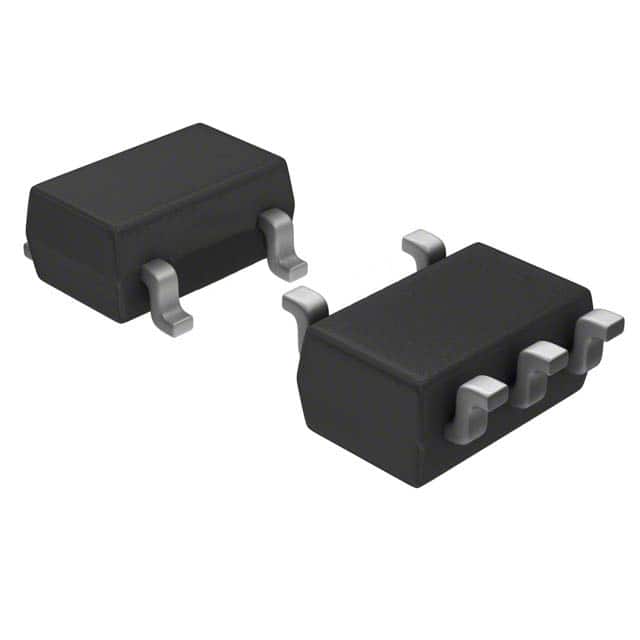
- Part No.:
- DS4303R-U+
- Manufacturer:
- Analog Devices Inc./Maxim Integrated
- Category:
- Voltage Reference
- Package:
- SC-74A, SOT-753
- Datasheet:
-
 DS4303R-U+.pdf
- Description:
- IC VREF SERIES ADJ 0.03% SOT23-5
- Quantity:
- Payment:

- Shipping:

Inventory:3,729
Please send an inquiry. Send us your inquiry, and we will respond immediately.
Product details
Overview
The DS4303R-U+ from Maxim Integrated is a nonvolatile electronically programmable voltage reference IC with 5-pin SOT23 package, ±1mV adjustment resolution, 2.4V–3.6V single-supply operation, and EEPROM-persistent output voltage storage. It serves as a factory-calibratable precision reference in power-supply feedback loops, sensor biasing, and threshold-setting circuits where post-assembly trimming is required.
For engineers reviewing the DS4303R-U+ datasheet, DS4303R-U+ pinout, DS4303R-U+ application, or DS4303R-U+ equivalent, key selection criteria include its ±1mV quantization accuracy, 11–15ms/V self-adjust settling time, -40°C to +85°C operating range, 200µVP-P (0.1Hz–10Hz) output noise, and ability to operate down to 300mV below VCC or above GND.
Technical Context
The DS4303R-U+ implements a closed-loop DAC-based self-adjust architecture: VIN is sampled, ADJ toggling initiates internal 12-bit DAC calibration until VOUT matches VIN within ±20mV tracking accuracy, then the result is stored in on-chip EEPROM. The device requires no external programming hardware-only stable VIN and a single low pulse on ADJ.
Its analog core includes a precision bandgap reference, rail-to-rail output stage capable of ±1mA drive, short-circuit protected VOUT, and integrated 95kΩ VIN pull-down and 18kΩ ADJ pull-up resistors. Temperature coefficient is specified as -31 to +6 ppm/°C at 3.0V output over +25°C to +85°C.
Key Specifications
| Parameter | Value and Actual Design Meaning |
|---|---|
| Output Voltage Range | 0.3V to (VCC – 0.3V); supports ultra-low-voltage biasing down to 300mV above GND or below VCC. |
| Adjust Resolution | ±1mV quantization step; enables final factory trim to meet tight system-level tolerance requirements. |
| Supply Current | 1.1–1.6mA typical; low quiescent draw suitable for battery-backed or always-on calibration nodes. |
| Temp Coefficient | -31 to +6 ppm/°C (at 3.0V, +25°C to +85°C); ensures <±0.5mV drift over full industrial temperature range. |
| Output Noise | 200µVP-P (0.1Hz–10Hz), 26µVRMS (10Hz–1kHz); low enough for high-resolution ADC reference applications. |
| EEPROM Endurance | 50,000 programming cycles at +70°C; supports repeated recalibration during production test or field service. |
| Line Regulation | ±4.0 to +1.0 mV/V; minimal output shift across supply variation-critical for systems with unregulated rails. |
Pinout & Package
DS4303R-U+ is housed in a lead-free 5-lead SOT23 package (3.0mm × 1.7mm × 1.3mm height), RoHS-compliant, with exposed pad not connected internally. Pin 1 is marked with a dot; top-view orientation places ADJ at pin 1, GND at pin 2, VIN at pin 3, VOUT at pin 4, and VCC at pin 5.
| Pin/Terminal | Circuit Role | Design Meaning |
|---|---|---|
| 1 - ADJ | Adjust control input | Active-low programming trigger; 100ns minimum low pulse initiates EEPROM write after VOUT self-adjust completes. |
| 2 - GND | Analog ground reference | Primary return path for VOUT load current and internal DAC; must be low-impedance for noise-sensitive applications. |
| 3 - VIN | Voltage sample input | Analog reference target for VOUT; internally sampled and held during adjustment; 95kΩ pull-down ensures defined state when open. |
| 4 - VOUT | Precision voltage output | Regulated, buffered output capable of ±1mA drive; short-circuit protected; 100pF max capacitive load recommended. |
| 5 - VCC | Positive supply input | 2.4V–3.6V single supply; powers all internal circuitry including EEPROM; requires local 0.01µF ceramic decoupling. |
Key Features
| Feature | Design Value |
|---|---|
| Nonvolatile voltage storage | EEPROM retains VOUT setting indefinitely across power cycles-eliminates need for backup power or external memory. |
| Automated factory trimming | ADJ-triggered self-adjust enables integration into bed-of-nails test fixtures without custom programming hardware. |
| Rail-to-rail output range | VOUT adjustable within 300mV of either supply rail-supports low-headroom biasing impossible with shunt references. |
| Post-assembly recalibration | VIN and ADJ remain accessible after PCB assembly; allows final trim after thermal aging or mechanical stress testing. |
| Integrated pull-up/pull-down | On-chip 18kΩ ADJ pull-up and 95kΩ VIN pull-down reduce BOM count and prevent floating inputs during idle states. |
Applications
| Power-Supply Calibration | Threshold Setting |
|---|---|
Use Scenario: Calibrating the feedback divider of a DC-DC converter in telecom power modules before shipment. IC Role / Device Role / Timing Role: Precision voltage reference providing stable, programmable setpoint for error amplifier comparison. Use Value: Enables ±1mV final trim to meet ±0.5% output regulation spec without manual potentiometer adjustment or laser trimming. | Use Scenario: Setting overvoltage lockout threshold in battery protection ICs for Li-ion packs. IC Role / Device Role / Timing Role: Adjustable reference input to comparator determining trip point for safety shutdown. Use Value: Allows batch-specific threshold tuning to compensate for cell voltage variance-no binning or custom resistors required. |
| Offset Nulling | Pressure Bridges |
Use Scenario: Nulling input offset in instrumentation amplifiers used in medical ECG front-ends. IC Role / Device Role / Timing Role: Programmable bias source injected into amplifier null pins to cancel DC offset pre-signal chain. Use Value: Achieves sub-10µV residual offset after trim-critical for high-gain, low-frequency biosignal acquisition. | Use Scenario: Biasing Wheatstone bridge sensors in industrial pressure transmitters. IC Role / Device Role / Timing Role: Stable excitation voltage source applied across bridge legs to generate ratiometric output. Use Value: Supports 0.3V–3.3V bridge drive range; low tempco ensures <±0.01% FS error contribution over -40°C to +85°C. |
Equivalent & Alternatives
The following parts are listed as comparable options for similar electronically programmable voltage reference applications.
| Alternative Part | Technical Difference | Application Difference | Selection Advice |
|---|---|---|---|
| MAX6190AESA+ | Fixed 2.5V output; no programmability; 3ppm/°C tempco; SO8 package | Suitable only for static reference needs-cannot replace DS4303R-U+ where post-assembly trim is required. | Select MAX6190AESA+ only if fixed voltage suffices and board space permits SO8; DS4303R-U+ preferred for flexible calibration. |
| LT6654BHS6-3.3#TRMPBF | Fixed 3.3V output; 3ppm/°C tempco; SOT23-6; no EEPROM or ADJ pin | Lacks in-system adjust capability-requires external DAC and microcontroller for programmability. | Choose LT6654BHS6-3.3#TRMPBF for ultra-low-noise fixed reference; DS4303R-U+ remains optimal for embedded trim autonomy. |
Compared with MAX6190AESA+ and LT6654BHS6-3.3#TRMPBF, the DS4303R-U+ uniquely integrates EEPROM storage, rail-to-rail programmability, and single-pin adjustment-enabling zero-footprint, hardware-only calibration without firmware or external DACs.
Availability
DS4303R-U+ is available at Aetrix Electronics and suitable for power-supply calibration, sensor biasing, threshold detection, and factory-trimmed instrumentation requiring stable component supply across automotive, industrial, and medical OEM programs.
Supply support for DS4303R-U+ includes scheduled delivery planning, volume procurement assistance, BOM continuity management, traceable sourcing, and lifecycle availability coordination for OEM customers, industrial embedded developers, connected-device designers, and electronics production programs.
Manufacturer
Maxim Integrated (now part of Analog Devices) designs precision analog, mixed-signal, and power management ICs for industrial, medical, and communications systems.
The DS4303R-U+ belongs to Maxim's programmable reference product line, engineered specifically to replace manual calibration methods with autonomous, in-circuit voltage trimming for high-mix manufacturing environments.
FAQ
What is the minimum stable voltage required on VIN to program the DS4303R-U+?
The DS4303R-U+ requires VIN to be stable within ±1mV during the entire self-adjust period. VIN must be between 0.3V and (VCC – 0.3V), with typical factory use at 1.200V ±0.001V for 1.2V output calibration. Instability exceeding ±1mV causes VOUTTA (±20mV tracking accuracy) to degrade, risking incomplete EEPROM write or inaccurate final value.
Can the DS4303R-U+ be reprogrammed after soldering onto a PCB?
Yes-the DS4303R-U+ supports full reprogramming post-assembly. Its SOT23-5 package exposes all pins, including ADJ and VIN, enabling bed-of-nails access. Reprogramming requires only stable VIN, a 100ns ADJ low pulse, and sufficient time for ∆V × tST settling (e.g., 12ms for 1V change). No reflow or disassembly is needed.
Does the DS4303R-U+ require external decoupling capacitors?
Yes-a 0.01µF ceramic capacitor must be placed between VCC and GND, mounted directly adjacent to pins 5 and 2. This is mandatory to suppress supply noise that could corrupt EEPROM writes or induce false ADJ triggering during power-up. Larger values (e.g., 0.1µF) may be added in parallel but do not replace the 0.01µF requirement.
What happens if ADJ is accidentally held low longer than tADJ during normal operation?
If ADJ is held low beyond the 100ns minimum (e.g., due to noise or layout coupling), the DS4303R-U+ will initiate a new self-adjust cycle once VIN stabilizes. This may overwrite the stored VOUT value. To prevent unintended programming, minimize ADJ trace length, avoid routing near noisy signals, and ensure no capacitance >10pF exists on the ADJ node per layout guidelines.
Is the DS4303R-U+ compatible with 1.8V logic systems?
No-the DS4303R-U+ requires VCC between 2.4V and 3.6V and has no 1.8V-compatible logic thresholds. Its ADJ input interprets logic low as <0.3×VCC (min -0.3V), so at VCC = 2.4V, VIL max is 0.72V-exceeding standard 1.8V logic low (<0.45V). Interfacing with 1.8V controllers requires level-shifting circuitry on the ADJ line.
DS4303R-U+ Specifications
- Product attributes
- Attribute value
- Manufacturer:
- Analog Devices Inc./Maxim Integrated
- Package/Case:
- SC-74A, SOT-753
- Series:
- -
- Packaging:
- Tube
- Product Status:
- Active
- Reference Type:
- Series
- Output Type:
- Adjustable
- Voltage - Output (Min/Fixed):
- 0.3V
- Voltage - Output (Max):
- 3.3 V
- Current - Output:
- 1 mA
- Tolerance:
- ±0.03%
- Temperature Coefficient:
- 62ppm/°C
- Noise - 0.1Hz to 10Hz:
- 200µVp-p
- Noise - 10Hz to 10kHz:
- 26µVp-p
- Voltage - Input:
- 2.4V ~ 3.6V
- Current - Supply:
- 1.6mA
- Current - Cathode:
- -
- Operating Temperature:
- -40°C ~ 85°C (TA)
- Grade:
- -
- Qualification:
- -
- Mounting Type:
- Surface Mount
- Supplier Device Package:
- SOT-23-5
DS4303R-U+ FAQ
1.How can I place an order for DS4303R-U+ through Aetrix?
Please submit a Request for Quotation (RFQ) for DS4303R-U+ on Aetrix. Our sales agent will provide a competitive quotation and guide you through the order confirmation once you accept the terms.
2.Are the price and stock information for DS4303R-U+ reliable?
The price and inventory of DS4303R-U+ are updated periodically and may fluctuate due to market conditions. Stock and pricing data are typically refreshed every 24 hours. Quotation validity for DS4303R-U+ is usually 5 days.
3.What payment methods are accepted for DS4303R-U+?
We accept Wire Transfer, PayPal, Credit Card, Western Union, MoneyGram, and Escrow for DS4303R-U+ transactions.
Note: Certain payment methods may incur a processing fee.
4.How is shipping managed for DS4303R-U+?
DS4303R-U+ orders can be shipped via leading logistics carriers, including DHL, UPS, FedEx, TNT, or Registered Mail.
Once your DS4303R-U+ order is processed, you will receive an email with the shipment details and tracking number.
Note: Tracking information may take up to 24 hours to appear. Express delivery typically takes 3–5 business days.
5.How can I obtain technical support or documentation for DS4303R-U+?
For technical support, including DS4303R-U+ datasheets, pinout diagrams, or application guidance, please contact our engineering support team. They can provide detailed documentation and assistance for your DS4303R-U+ requirements.
6.How does Aetrix verify that DS4303R-U+ is sourced from the original manufacturer or authorized distributors?
All DS4303R-U+ products on Aetrix are procured from qualified distributors and authorized channels. Our dedicated quality assurance team conducts strict verification, including traceability checks and, if necessary, third-party testing. This ensures that DS4303R-U+ meets industry standards.
7.What is the process for return or replacement of DS4303R-U+?
All DS4303R-U+ units undergo pre-shipment inspection (PSI). If there is an issue with DS4303R-U+, returns or replacements are accepted under the following conditions:
1.Quantity discrepancies, incorrect items, or visible external defects (such as breakage or corrosion), acknowledged by Aetrix.
2.The issue is reported within 90 days of delivery.
3.The DS4303R-U+ part is unused and in its original packaging.
Return procedure for DS4303R-U+:
1.Submit a request within 90 days.
2.Obtain a Return Material Authorization (RMA) from Aetrix.
DS4303R-U+ Tags
-
TL431AIDBZR
Texas Instruments
-
TL431BQDBZR
Texas Instruments

-
AN431AN-ATRG1
Diodes Incorporated
-
LM4040CYM3-2.5-TR
Microchip Technology
-
LM4040CYM3-4.1-TR
Microchip Technology
-
LM4040EIM3-2.5/NOPB
Texas Instruments
-
AZ431LBNTR-G1
Diodes Incorporated
-
LM4040D20IDBZR
Texas Instruments
-
LM4041DIM3-ADJ/NOPB
Texas Instruments
-
LM4040DIM3X-2.5/NOPB
Texas Instruments
-
LM4040DIM3-2.5/NOPB
Texas Instruments
-
AZ431LANTR-G1
Diodes Incorporated
Tech Hub

A practical engineering guide to 3.3V and 5V logic compatibility, input thresholds, resistor dividers, translator ICs, MOSFET level shifting, I2C pull-ups, timing limits and power-sequencing risks.

The 74HC595 uses push-pull logic outputs, while the TPIC6B595 uses 50 V open-drain DMOS sinks for higher-power loads. This guide compares timing, current limits, 3.3 V interfacing, load wiring, thermal…

The 74HC595 converts serial data into eight stable parallel outputs. This guide covers pin functions, shift and storage timing, OE and MR behavior, drive-current limits, cascading, voltage compatibilit…

A technical comparison of level-sensitive latches and edge-triggered flip-flops, covering timing windows, setup and hold limits, master–slave operation, time borrowing, race-through, HDL inference and…

A D latch stores one bit while Enable controls when data can pass. This reference covers gate-level operation, truth tables, transparency, setup and hold timing, LE versus OE, common ICs and practical …

An SR latch stores one bit through cross-coupled feedback. This engineering reference covers NOR and NAND implementations, truth tables, forbidden-state recovery, gated operation, switch debouncing, fa…

Latch circuits retain one bit through feedback. This technical reference covers SR and D latches, truth tables, transparency, timing limits, latch-versus-flip-flop behavior, applications and common log…

An engineering guide to LED driver operation, constant-current and constant-voltage outputs, linear and switching topologies, dimming, IC selection, calculations, replacement compatibility, and fault c…

Operational amplifier guide covering op amp basics, feedback, ideal vs real op amps, common configurations, buffer circuits, offset, bias current, gain-bandwidth, slew rate, rail-to-rail limits and sel…

Jumper cables guide covering safe connection order, red and black clamp placement, final ground connection, cable gauge, length, clamp quality, copper vs CCA cables, jump starter comparison and battery…


