
 My Inquiry
 My Account


Analog Devices Inc./Maxim Integrated DS80C320-ENG
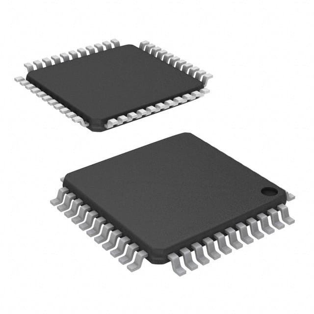
- Part No.:
- DS80C320-ENG
- Manufacturer:
- Analog Devices Inc./Maxim Integrated
- Category:
- Microcontrollers
- Package:
- 44-TQFP
- Datasheet:
-
 DS80C320-ENG.pdf
- Description:
- IC MCU 8BIT ROMLESS 44TQFP
- Quantity:
- Payment:

- Shipping:

Inventory:4,714
Please send an inquiry. Send us your inquiry, and we will respond immediately.
Product details
Overview
DS80C320-ENG from Maxim Integrated is a high-speed, 80C32-compatible 8-bit microcontroller designed for industrial embedded control upgrades. It delivers 25 MHz maximum crystal frequency, 4-clock-per-machine-cycle architecture (vs. legacy 12), dual hardware serial ports, 256 bytes on-chip RAM, and operates from –40°C to +85°C in 44-pin TQFP. It serves as a drop-in performance upgrade in legacy 5V 8051-based motor control, instrumentation, and industrial HMI systems.
For engineers reviewing the DS80C320-ENG datasheet, DS80C320-ENG pinout, DS80C320-ENG application, or DS80C320-ENG equivalent, this page provides verified electrical parameters, validated TQFP-44 pin mapping, confirmed dual-serial-port timing behavior, stretchable MOVX memory access configuration, and real-world substitution guidance for legacy 80C32 designs requiring higher throughput without PCB redesign.
Technical Context
The DS80C320-ENG implements a rearchitected 8051 core eliminating wasted clock cycles: all instructions execute in 4–28 oscillator cycles (vs. 12–48 in standard 80C32), with 159 opcodes achieving 3× speedup. Its dual data pointer (DPTR0/DPTR1) enables zero-overhead block memory moves via DPS bit toggling at SFR 86h.
Peripherals include two independent full-duplex UARTs (Serial Port 0 on P3.0/P3.1; Serial Port 1 on P1.2/P1.3), programmable watchdog timer, early-warning power-fail interrupt, and configurable MOVX strobe width (2–9 machine cycles via CKCON.2–0). Timer 0/1/2 default to 12-clock mode on reset for backward compatibility but support 4-clock operation when CKCON bits are set.
Key Specifications
| Parameter | Value and Actual Design Meaning |
|---|---|
| Core Architecture | 80C32-compatible 8-bit CPU with 4-clock-per-machine-cycle execution (vs. 12-clock legacy); enables 2.5× average instruction speedup. |
| Max Clock Frequency | 25 MHz crystal input (–40°C to +85°C industrial grade); supports apparent 62.5 MIPS throughput at full speed. |
| On-Chip Memory | 256 bytes scratchpad RAM; no internal ROM - requires external 64kB program memory via multiplexed P0/P2 bus. |
| Serial Interfaces | Two independent full-duplex UARTs: SP0 (P3.0/RXD0, P3.1/TXD0) and SP1 (P1.2/RXD1, P1.3/TXD1), each with dedicated SCON/SBUF registers. |
| Memory Access Control | Stretchable MOVX timing: software-selectable 2–9 machine-cycle strobe width (CKCON.2–0) for mixed-speed RAM/peripheral interfacing without glue logic. |
| Power Supply Range | 4.25 V to 5.5 V - maintains compatibility with legacy 5V TTL/CMOS systems while enabling stable high-speed operation. |
| Operating Temperature | –40°C to +85°C - qualified for industrial automation, factory-floor controllers, and outdoor instrumentation environments. |
Pinout & Package
DS80C320-ENG is supplied in a 44-pin Thin Quad Flat Package (TQFP) with 0.8 mm pitch, 10 mm × 10 mm body, and exposed thermal pad (non-electrical). Pin 1 is marked by dot; pins numbered counterclockwise.
| Pin/Terminal | Circuit Role | Design Meaning |
|---|---|---|
| VCC (Pin 17) | Primary Power Supply | +5V supply input; must be decoupled locally with 0.1 µF ceramic capacitor to GND (Pin 4). |
| GND (Pin 4) | Digital Ground Reference | Common return path for all digital I/O and core logic; connects to system ground plane. |
| RST (Pin 14) | Active-High Reset Input | Schmitt-triggered input with internal pulldown; accepts external RC or pushbutton reset; no external pullup required. |
| XTAL1 (Pin 15), XTAL2 (Pin 16) | Clock Oscillator Interface | Supports parallel-resonant AT-cut crystals up to 25 MHz; XTAL1 accepts external clock source if crystal omitted. |
| P0.0–P0.7 (Pins 33–38, 26, 27) | Multiplexed Address/Data Bus | AD0–AD7: outputs low-order address during ALE high; functions as bidirectional data bus during MOVX/MOVC; no internal latch - requires external 74LS373 if latching needed. |
| P1.0–P1.7 (Pins 40–44, 1–3) | General-Purpose I/O with Alternate Functions | Includes T2/T2EX (P1.0/P1.1), RXD1/TXD1 (P1.2/P1.3), and INT2–INT5 (P1.4–P1.7); weak pullups active on reset. |
| P2.0–P2.7 (Pins 18–25) | High-Order Address Bus (A8–A15) | Outputs upper address byte during external memory access; value reflects internal latch during MOVX @Ri operations. |
| P3.0–P3.7 (Pins 5–13) | Multiplexed I/O with System Functions | Provides RXD0/TXD0 (P3.0/P3.1), INT0/INT1 (P3.2/P3.3), T0/T1 (P3.4/P3.5), WR/ RD (P3.6/P3.7); all pins have weak pullups and strong pulldown on write-0. |
| EA (Pin 29) | External Access Enable | Must be hardwired to GND to force all code fetches from external ROM; no internal program memory. |
Key Features
| Feature | Design Value |
|---|---|
| Dual Data Pointer (DPTR0/DPTR1) | Reduces 64-byte memory block move from 1869 to 1097 machine cycles (42% fewer cycles) by eliminating address reload overhead. |
| Configurable MOVX Strobe Width | Software-selectable 2–9 machine-cycle read/write strobe (via CKCON.2–0) enables direct interface to 120 ns RAM and slow peripherals like LCDs without wait-state logic. |
| Second Hardware UART (SP1) | Full-duplex serial port on P1.2/P1.3 with independent SCON1/SBUF1 registers - supports simultaneous host/debug and sensor/device communication streams. |
| Power-Fail Detection & Early Warning | Hardware-generated interrupt and reset triggered by monitored VCC drop below 4.25 V - enables safe state save and controlled shutdown in brownout conditions. |
| Programmable Watchdog Timer | Independent timeout counter with software-reset capability - prevents system lockup in unattended industrial controllers without external supervision circuitry. |
Applications
| Industrial Motor Control | Factory Floor Instrumentation |
|---|---|
Use Scenario: Real-time closed-loop control of stepper/servo drives using PWM outputs and quadrature encoder feedback. IC Role / Device Role / Timing Role: Primary controller executing motion profiles, managing I/O, and communicating via RS-485 (SP0) and CAN gateway (SP1 via external transceiver). Use Value: 25 MHz clock + 4-cycle core enables sub-100 µs PID loop execution; dual UARTs isolate fieldbus traffic from debug channel without software multiplexing. |
Use Scenario: Multi-sensor data acquisition (temperature, pressure, flow) with local display and Ethernet gateway reporting. IC Role / Device Role / Timing Role: Central data aggregator reading analog front-ends via GPIO/timers, driving segmented LCD via slow MOVX, and transmitting packets over RS-232 (SP0) and RS-485 (SP1). Use Value: Stretchable MOVX allows direct connection to 200 ns LCD controller; power-fail interrupt triggers EEPROM save of last valid readings before shutdown. |
| Legacy System Upgrade | Embedded HMI Controller |
Use Scenario: Drop-in replacement for aging 80C32-based medical device controller requiring faster boot time and enhanced diagnostics. IC Role / Device Role / Timing Role: Pin-compatible upgrade retaining same PCB layout and firmware base; leverages dual DPTR for faster calibration table loading from external Flash. Use Value: 2.5× average speedup reduces boot sequence from 1.2 s to <500 ms; watchdog timer ensures fail-safe restart after firmware update corruption. |
Use Scenario: Touchscreen-enabled operator interface for HVAC control panel with local logic and remote monitoring. IC Role / Device Role / Timing Role: Manages capacitive touch scan, drives graphical LCD via 8-bit parallel bus, and communicates status via SP0 (USB-UART bridge) and SP1 (Modbus RTU). Use Value: Dual UARTs eliminate need for external UART expander; industrial temp range ensures reliability inside metal enclosures with ambient temps up to 85°C. |
Equivalent & Alternatives
The following parts are listed as comparable options for similar 8-bit microcontroller applications.
| Alternative Part | Technical Difference | Application Difference | Selection Advice |
|---|---|---|---|
| DS80C320-ECL | Same core and peripherals, but rated for 0°C to +70°C and supports 33 MHz max crystal (vs. 25 MHz for DS80C320-ENG). | Targeted at commercial-grade applications where extended temperature is unnecessary and higher throughput justifies tighter timing margins. | Select DS80C320-ECL only if ambient operating temperature stays within 0–70°C and system design accommodates 33 MHz timing constraints. |
| AT89C51RD2-RLTUM | Enhanced 8051 with 64 kB Flash, 1.25 kB RAM, and single UART; lacks dual DPTR, stretch MOVX, and second UART; operates at 33 MHz but with 12-clock core. | Lower-cost solution for non-critical timing applications where external Flash suffices and dual serial links are not required. | Choose AT89C51RD2-RLTUM only when firmware storage flexibility outweighs need for deterministic high-speed peripheral interfacing. |
Compared with DS80C320-ECL, DS80C320-ENG trades 8 MHz clock headroom for guaranteed –40°C startup and sustained operation in harsh environments; compared with AT89C51RD2-RLTUM, it delivers deterministic 4-cycle timing, dual UARTs, and MOVX configurability essential for real-time industrial I/O - making it the sole choice for legacy 80C32 upgrades demanding both speed and ruggedness.
Availability
DS80C320-ENG is available at Aetrix Electronics and suitable for industrial motor control, factory floor instrumentation, legacy system upgrades, and embedded HMI applications requiring stable component supply across extended temperature ranges and long production lifecycles.
Supply support for DS80C320-ENG includes scheduled delivery planning, volume procurement assistance, BOM continuity management, traceable sourcing, and lifecycle availability coordination for OEM customers, industrial embedded developers, connected-device designers, and electronics production programs.
Manufacturer
Maxim Integrated (now part of Analog Devices) is a semiconductor company specializing in precision analog, mixed-signal, and high-reliability microcontrollers for industrial, medical, and automotive applications.
The DS80C320-ENG belongs to Maxim's high-speed 8051-compatible microcontroller family, engineered specifically to extend the life of legacy 5V 80C32 designs with measurable performance gains while preserving software and hardware investment.
FAQ
Is DS80C320-ENG pin-compatible with standard 80C32 devices in 44-pin TQFP packages?
Yes, DS80C320-ENG is fully pin-compatible with the industry-standard 80C32 in 44-pin TQFP packaging. All signal names, pin positions, and electrical characteristics align per Maxim's datasheet - enabling direct PCB-level replacement without layout changes. The DS80C320-ENG retains identical P0–P3 port mappings, reset, crystal, and EA pin locations, ensuring mechanical and functional interchangeability in existing 80C32 designs.
What is the default MOVX memory access timing for DS80C320-ENG after power-on reset?
After power-on reset, DS80C320-ENG defaults to a 3-machine-cycle MOVX strobe width (CKCON.2–0 = 001b), resulting in a 160 ns strobe at 25 MHz. This setting ensures compatibility with common 120 ns and 150 ns SRAM parts without requiring external wait-state generation. To achieve maximum speed, software must explicitly write CKCON = 0x00 to select 2-cycle mode (80 ns strobe at 25 MHz).
Does DS80C320-ENG support both Timer 1 and Timer 2 for baud rate generation on Serial Port 1?
No, DS80C320-ENG supports Timer 1 only for baud rate generation on Serial Port 1 (SP1). Unlike Serial Port 0 (SP0), which can use Timer 1 or Timer 2, SP1's baud rate is exclusively derived from Timer 1 - as documented in the High-Speed Microcontroller User's Guide. Timer 2 remains available for SP0 or general-purpose counting, but cannot serve SP1 timing.
How does the power-fail interrupt function in DS80C320-ENG, and what voltage threshold triggers it?
The DS80C320-ENG features an internal power-fail comparator that asserts the power-fail interrupt when VCC drops below 4.25 V - matching its minimum operating specification. This early-warning signal occurs before the device reaches reset threshold (typically ~3.8 V), allowing firmware to execute critical save routines (e.g., EEPROM writes) within ~10–20 ms before brownout shutdown. The interrupt is edge-triggered and requires software acknowledgment.
Can DS80C320-ENG operate reliably at 33 MHz, or is that rating exclusive to other variants?
DS80C320-ENG is rated for a maximum crystal frequency of 25 MHz across its full –40°C to +85°C operating range. While higher-speed variants like DS80C320-ENL support 33 MHz, the DS80C320-ENG's 25 MHz limit is thermally and electrically validated for industrial temperature stability. Attempting 33 MHz operation risks timing violations, especially in worst-case corners, and voids guaranteed specifications.
DS80C320-ENG Specifications
- Product attributes
- Attribute value
- Manufacturer:
- Analog Devices Inc./Maxim Integrated
- Package/Case:
- 44-TQFP
- Series:
- 80C
- Packaging:
- Tray
- Product Status:
- Obsolete
- Programmable:
- Not Verified
- Core Processor:
- 8051
- Core Size:
- 8-Bit
- Speed:
- 25MHz
- Connectivity:
- EBI/EMI, SIO, UART/USART
- Peripherals:
- Power-Fail Reset, WDT
- Number of I/O:
- 32
- Program Memory Size:
- -
- Program Memory Type:
- ROMless
- EEPROM Size:
- -
- RAM Size:
- 256 x 8
- Voltage - Supply (Vcc/Vdd):
- 4.5V ~ 5.5V
- Data Converters:
- -
- Oscillator Type:
- External
- Operating Temperature:
- -40°C ~ 85°C (TA)
- Grade:
- -
- Qualification:
- -
- Mounting Type:
- Surface Mount
- Supplier Device Package:
DS80C320-ENG FAQ
1.How can I place an order for DS80C320-ENG through Aetrix?
Please submit a Request for Quotation (RFQ) for DS80C320-ENG on Aetrix. Our sales agent will provide a competitive quotation and guide you through the order confirmation once you accept the terms.
2.Are the price and stock information for DS80C320-ENG reliable?
The price and inventory of DS80C320-ENG are updated periodically and may fluctuate due to market conditions. Stock and pricing data are typically refreshed every 24 hours. Quotation validity for DS80C320-ENG is usually 5 days.
3.What payment methods are accepted for DS80C320-ENG?
We accept Wire Transfer, PayPal, Credit Card, Western Union, MoneyGram, and Escrow for DS80C320-ENG transactions.
Note: Certain payment methods may incur a processing fee.
4.How is shipping managed for DS80C320-ENG?
DS80C320-ENG orders can be shipped via leading logistics carriers, including DHL, UPS, FedEx, TNT, or Registered Mail.
Once your DS80C320-ENG order is processed, you will receive an email with the shipment details and tracking number.
Note: Tracking information may take up to 24 hours to appear. Express delivery typically takes 3–5 business days.
5.How can I obtain technical support or documentation for DS80C320-ENG?
For technical support, including DS80C320-ENG datasheets, pinout diagrams, or application guidance, please contact our engineering support team. They can provide detailed documentation and assistance for your DS80C320-ENG requirements.
6.How does Aetrix verify that DS80C320-ENG is sourced from the original manufacturer or authorized distributors?
All DS80C320-ENG products on Aetrix are procured from qualified distributors and authorized channels. Our dedicated quality assurance team conducts strict verification, including traceability checks and, if necessary, third-party testing. This ensures that DS80C320-ENG meets industry standards.
7.What is the process for return or replacement of DS80C320-ENG?
All DS80C320-ENG units undergo pre-shipment inspection (PSI). If there is an issue with DS80C320-ENG, returns or replacements are accepted under the following conditions:
1.Quantity discrepancies, incorrect items, or visible external defects (such as breakage or corrosion), acknowledged by Aetrix.
2.The issue is reported within 90 days of delivery.
3.The DS80C320-ENG part is unused and in its original packaging.
Return procedure for DS80C320-ENG:
1.Submit a request within 90 days.
2.Obtain a Return Material Authorization (RMA) from Aetrix.
DS80C320-ENG Tags

-
ATTINY4-TSHR
Microchip Technology
-
ATTINY10-TSHR
Microchip Technology
-
ATTINY10-TS8R
Microchip Technology

-
ATTINY202-SSNR
Microchip Technology
-
ATTINY202-SSFR
Microchip Technology
-
ATTINY402-SSNR
Microchip Technology

-
PIC16F15213T-I/MF
Microchip Technology
-
PIC16F15213-E/MF
Microchip Technology

-
PIC10F200T-I/OT
Microchip Technology
-
ATTINY412-SSNR
Microchip Technology
-
PIC10F202T-I/OT
Microchip Technology

-
ATTINY404-SSNR
Microchip Technology
Tech Hub

A practical engineering guide to 3.3V and 5V logic compatibility, input thresholds, resistor dividers, translator ICs, MOSFET level shifting, I2C pull-ups, timing limits and power-sequencing risks.

The 74HC595 uses push-pull logic outputs, while the TPIC6B595 uses 50 V open-drain DMOS sinks for higher-power loads. This guide compares timing, current limits, 3.3 V interfacing, load wiring, thermal…

The 74HC595 converts serial data into eight stable parallel outputs. This guide covers pin functions, shift and storage timing, OE and MR behavior, drive-current limits, cascading, voltage compatibilit…

A technical comparison of level-sensitive latches and edge-triggered flip-flops, covering timing windows, setup and hold limits, master–slave operation, time borrowing, race-through, HDL inference and…

A D latch stores one bit while Enable controls when data can pass. This reference covers gate-level operation, truth tables, transparency, setup and hold timing, LE versus OE, common ICs and practical …

An SR latch stores one bit through cross-coupled feedback. This engineering reference covers NOR and NAND implementations, truth tables, forbidden-state recovery, gated operation, switch debouncing, fa…

Latch circuits retain one bit through feedback. This technical reference covers SR and D latches, truth tables, transparency, timing limits, latch-versus-flip-flop behavior, applications and common log…

An engineering guide to LED driver operation, constant-current and constant-voltage outputs, linear and switching topologies, dimming, IC selection, calculations, replacement compatibility, and fault c…

Operational amplifier guide covering op amp basics, feedback, ideal vs real op amps, common configurations, buffer circuits, offset, bias current, gain-bandwidth, slew rate, rail-to-rail limits and sel…

Jumper cables guide covering safe connection order, red and black clamp placement, final ground connection, cable gauge, length, clamp quality, copper vs CCA cables, jump starter comparison and battery…


