
 My Inquiry
 My Account


Texas Instruments DS90CF363BMT/NOPB
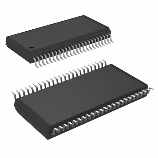
- Part No.:
- DS90CF363BMT/NOPB
- Manufacturer:
- Texas Instruments
- Category:
- Specialized
- Package:
- 48-TFSOP (0.240", 6.10mm Width)
- Datasheet:
-
 DS90CF363BMT/NOPB.pdf
- Description:
- IC INTERFACE SPECIALIZED 48TSSOP
- Quantity:
- Payment:

- Shipping:

Inventory:9,506
Please send an inquiry. Send us your inquiry, and we will respond immediately.
Product details
Overview
DS90CF363BMT/NOPB from Texas Instruments is a +3.3V programmable LVDS transmitter for 18-bit flat panel display (FPD) Link applications, supporting 18–68 MHz shift clock and delivering up to 1.3 Gbps throughput across three LVDS data lanes plus one LVDS clock lane. It converts 21 CMOS/TTL inputs (18 RGB + 3 control) into LVDS differential streams and features integrated PLL with no external components required. Used in LCD timing interfaces for VGA/SVGA/XGA/Dual-Pixel SXGA displays.
For engineers reviewing the DS90CF363BMT/NOPB datasheet, DS90CF363BMT/NOPB pinout, DS90CF363BMT/NOPB application, or DS90CF363BMT/NOPB equivalent, key selection criteria include FPD-Link falling-edge strobe compatibility, 345 mV typical LVDS swing, <130 mW power consumption at 65 MHz, spread-spectrum clock support up to 100 kHz ±2.5%, and TSSOP-48 package integration with robust input sequencing.
Technical Context
The DS90CF363BMT/NOPB implements a fixed falling-edge strobe architecture synchronized to TxCLKIN, sampling 21 parallel TTL inputs per clock cycle and mapping them to four LVDS differential pairs (three data, one clock). Its PLL locks to input clock frequencies from 18–68 MHz without external loop filter components and maintains precise bit-to-bit timing alignment-e.g., TPPos0 = ±0.20 ns at 65 MHz.
It supports dual power domains: VCC/PLL VCC/LVDS VCC are all +3.3V supplies, with separate ground pins for TTL, PLL, and LVDS sections to minimize noise coupling. The device includes input clock detection logic that forces all LVDS outputs low when TxCLKIN is missing and /PD is high, enabling fail-safe behavior in display timing systems.
Key Specifications
| Parameter | Value and Actual Design Meaning |
|---|---|
| Supply Voltage | 3.0–3.6 V - Enables direct interface with 3.3V logic families without level-shifting. |
| LVDS Differential Swing | 250–450 mV (typ 345 mV) - Ensures reliable signal integrity over 100 Ω termination while minimizing EMI. |
| Max Data Rate | 1.3 Gbps total - Achieved via 455 Mbps per LVDS data channel × 3 channels + clock, supporting 170 MB/s bandwidth. |
| Power Consumption | <130 mW at 65 MHz - 40% lower than BiCMOS alternatives, reducing thermal load in compact display modules. |
| Power-Down Current | <37 μW (typ) - Places LVDS drivers in high-impedance state, eliminating dynamic current draw during display blanking. |
| Input Clock Range | 18–68 MHz - Covers VGA (25 MHz), SVGA (40 MHz), XGA (65 MHz), and Dual-Pixel SXGA timing requirements. |
| Spread Spectrum Support | Up to 100 kHz modulation with ±2.5% center spread or −5% down spread - Reduces EMI peak emissions in FCC/CE-compliant displays. |
Pinout & Package
DS90CF363BMT/NOPB uses a 48-pin TSSOP (DGG0048A) package with 0.5 mm pitch, 12.4–12.6 mm length, 6.0–6.2 mm width, and 1.2 mm max height. Pin 1 marked with corner chamfer; recommended land pattern per IPC-7351.
| Pin/Terminal | Circuit Role | Design Meaning |
|---|---|---|
| TxIN[0:20] | CMOS/TTL Input | 21-bit parallel input: 6R/6G/6B + FPLINE/FPFRAME/DRDY - accepts 3.3V LVTTL/LVCMOS only (not 5V tolerant). |
| FPSHIFT IN (TxCLKIN) | CMOS/TTL Clock Input | Falling-edge strobe clock input; no special power-up sequencing required relative to data or /PD. |
| PWR DOWN | CMOS/TTL Control Input | Active-low enable: asserts TRI-STATE on all LVDS outputs and disables PLL for ultra-low standby current. |
| TxOUT+[0:2], TxOUT−[0:2] | LVDS Differential Output | Three LVDS data pairs carrying serialized RGB/control bits; each pair requires 100 Ω differential termination. |
| TxCLK OUT+, TxCLK OUT− | LVDS Differential Output | Dedicated LVDS clock pair synchronized to data; enables source-synchronous timing at receiver (e.g., DS90CF366). |
| VCC, PLL VCC, LVDS VCC | Power Supply Inputs | Three independent +3.3V supply pins - decoupled separately to isolate noise between TTL, PLL, and LVDS output domains. |
| GND, PLL GND, LVDS GND | Ground Terminals | Four TTL GND, two PLL GND, three LVDS GND - maintain domain-specific return paths to suppress crosstalk. |
Key Features
| Feature | Design Value |
|---|---|
| Integrated PLL with zero external components | Eliminates loop filter capacitors/resistors, reducing BOM count and PCB area in space-constrained display interfaces. |
| Falling-edge strobe architecture | Ensures interoperability with DS90CF366 receiver without translation logic, simplifying FPD-Link chipset design. |
| Input clock detection & automatic output disable | Prevents undefined LVDS output states during clock loss, improving system reliability in hot-plug or mode-switch scenarios. |
| Robust input sequencing | Allows TxCLKIN/data to be applied before or after power-up and after /PD deassertion - no reset coordination needed. |
| 18–68 MHz shift clock support | Covers full range from VGA to Dual-Pixel SXGA resolutions, enabling single-transmitter reuse across multiple display formats. |
Applications
| LCD Timing Interface | Embedded Display Module |
|---|---|
|
Use Scenario: Driving 18-bit RGB + control signals from GPU or display controller to TFT-LCD panel via twisted-pair cable. IC Role / Device Role / Timing Role: FPD-Link transmitter converting parallel TTL to serialized LVDS with embedded clock for EMI-resistant transmission. Use Value: Replaces wide 21-bit TTL bus with 4-lane LVDS, cutting cable width by >60% and lowering radiated emissions per TIA/EIA-644. |
Use Scenario: Integrating display interface into industrial HMI or medical monitor with strict thermal and EMC constraints. IC Role / Device Role / Timing Role: Low-power LVDS serializer enabling compact PCB layout and passive cooling in sealed enclosures. Use Value: 130 mW max power at 65 MHz and 345 mV LVDS swing reduce heat generation and simplify compliance with IEC 61000-4-3 radiated immunity. |
| Video Graphics Adapter | Automotive Infotainment Display |
|
Use Scenario: Adding LVDS output capability to legacy VGA/SVGA graphics cards using discrete timing controllers. IC Role / Device Role / Timing Role: Falling-edge strobe transmitter compatible with standard GPU pixel clocks and sync signals. Use Value: Pin-for-pin replacement for DS90CF363A and backward-compatible with DS90C363, easing upgrade paths. |
Use Scenario: Transmitting video from head unit SoC to central dashboard display in vehicles with spread-spectrum clocking. IC Role / Device Role / Timing Role: LVDS transmitter supporting 100 kHz SSCG with ±2.5% deviation to meet automotive CISPR 25 Class 5 limits. Use Value: Integrated SSCG tracking eliminates need for external clock modulator IC, reducing component count and board space. |
Equivalent & Alternatives
The following parts are listed as comparable options for similar LVDS FPD-Link transmitter applications.
| Alternative Part | Technical Difference | Application Difference | Selection Advice |
|---|---|---|---|
| DS90CF363AMT/NOPB | Previous revision with identical pinout but higher power consumption (~180 mW at 65 MHz) and no spread-spectrum support. | Lacks SSCG tracking; not suitable for new designs requiring EMI reduction via clock modulation. | Select DS90CF363BMT/NOPB for lower power, SSCG, and improved set/hold timing margins. |
| SN75LVDS84PWR | TI's earlier 18-bit LVDS transmitter; requires external PLL components and lacks input clock detection logic. | Higher BOM cost and larger footprint due to external loop filter; no automatic clock-loss response. | Choose DS90CF363BMT/NOPB for integrated PLL, smaller TSSOP-48 footprint, and enhanced system-level fault tolerance. |
Compared with DS90CF363AMT/NOPB and SN75LVDS84PWR, DS90CF363BMT/NOPB delivers 40% lower power, built-in spread-spectrum clock tracking, and autonomous clock-loss handling - making it the preferred choice for new FPD-Link designs targeting EMI compliance, thermal efficiency, and functional safety.
Availability
DS90CF363BMT/NOPB is available at Aetrix Electronics and suitable for LCD timing interfaces, embedded display modules, video graphics adapters, and automotive infotainment displays requiring stable component supply, long-term lifecycle support, and RoHS-compliant packaging.
Supply support for DS90CF363BMT/NOPB includes scheduled delivery planning, volume procurement assistance, BOM continuity management, traceable sourcing, and lifecycle availability coordination for OEM customers, industrial embedded developers, connected-device designers, and electronics production programs.
Manufacturer
Texas Instruments is a global semiconductor leader specializing in analog, embedded processing, and connectivity technologies, with decades of experience in display interface solutions.
DS90CF363BMT/NOPB belongs to TI's FPD-Link family, designed specifically for high-speed, low-EMI serialization of RGB and timing signals in flat-panel display systems - balancing performance, power, and PCB integration.
FAQ
What is the operating temperature range for DS90CF363BMT/NOPB?
The DS90CF363BMT/NOPB is specified for operation from −10°C to +70°C ambient temperature. This industrial-grade range supports deployment in commercial and industrial display systems, including enclosed HMIs and automotive cabin environments where ambient temperatures remain within this envelope. The device's thermal derating (16 mW/°C above +25°C) ensures safe operation under sustained load conditions.
Does DS90CF363BMT/NOPB support 5V logic inputs?
No, DS90CF363BMT/NOPB does not support 5V logic inputs. Its TxIN and FPSHIFT IN pins accept only 3.3V LVTTL/LVCMOS levels and are not 5V tolerant. Applying 5V signals may damage the inputs. When interfacing with 5V sources, level-shifting circuitry is required - or consider migration to a 5V-compatible FPD-Link transmitter such as DS90CF563 (discontinued) with appropriate redesign.
Can DS90CF363BMT/NOPB be used with a rising-edge strobe receiver?
No, DS90CF363BMT/NOPB is a fixed falling-edge strobe transmitter and is designed to interoperate only with falling-edge strobe receivers like the DS90CF366. Using it with a rising-edge strobe receiver (e.g., DS90CF364) would result in timing misalignment and data corruption. No internal configuration or external logic can convert its strobe polarity - system-level redesign is required for rising-edge compatibility.
What is the minimum pulse width required on the PWR DOWN pin of DS90CF363BMT/NOPB?
The DS90CF363BMT/NOPB requires a minimum pulse width of 1 µs on the PWR DOWN pin to reliably enter power-down mode. This specification ensures complete tri-state of LVDS outputs and full PLL disablement. Shorter pulses may result in incomplete power-down behavior or metastability. The device also supports asynchronous assertion - PWR DOWN can be asserted at any time, even during active data transmission.
How does DS90CF363BMT/NOPB handle missing input clock conditions?
DS90CF363BMT/NOPB includes dedicated "Input Clock Detection" logic: when TxCLKIN is absent and PWR DOWN is high, all LVDS output pairs (data and clock) are pulled to logic low. This prevents undefined differential states on the link, avoiding false triggering or noise injection at the receiver. The feature operates autonomously without software or external supervision, enhancing system robustness during display sleep or source reconfiguration.
DS90CF363BMT/NOPB Specifications
- Product attributes
- Attribute value
- Manufacturer:
- Texas Instruments
- Series:
- -
- Package/Case:
- 48-TFSOP (0.240", 6.10mm Width)
- Packaging:
- Tube
- Product Status:
- Active
- Applications:
- -
- Interface:
- -
- Voltage - Supply:
- 3V ~ 3.6V
- Supplier Device Package:
- 48-TSSOP
- Grade:
- -
- Qualification:
- -
- Mounting Type:
- Surface Mount
DS90CF363BMT/NOPB FAQ
1.How can I place an order for DS90CF363BMT/NOPB through Aetrix?
Please submit a Request for Quotation (RFQ) for DS90CF363BMT/NOPB on Aetrix. Our sales agent will provide a competitive quotation and guide you through the order confirmation once you accept the terms.
2.Are the price and stock information for DS90CF363BMT/NOPB reliable?
The price and inventory of DS90CF363BMT/NOPB are updated periodically and may fluctuate due to market conditions. Stock and pricing data are typically refreshed every 24 hours. Quotation validity for DS90CF363BMT/NOPB is usually 5 days.
3.What payment methods are accepted for DS90CF363BMT/NOPB?
We accept Wire Transfer, PayPal, Credit Card, Western Union, MoneyGram, and Escrow for DS90CF363BMT/NOPB transactions.
Note: Certain payment methods may incur a processing fee.
4.How is shipping managed for DS90CF363BMT/NOPB?
DS90CF363BMT/NOPB orders can be shipped via leading logistics carriers, including DHL, UPS, FedEx, TNT, or Registered Mail.
Once your DS90CF363BMT/NOPB order is processed, you will receive an email with the shipment details and tracking number.
Note: Tracking information may take up to 24 hours to appear. Express delivery typically takes 3–5 business days.
5.How can I obtain technical support or documentation for DS90CF363BMT/NOPB?
For technical support, including DS90CF363BMT/NOPB datasheets, pinout diagrams, or application guidance, please contact our engineering support team. They can provide detailed documentation and assistance for your DS90CF363BMT/NOPB requirements.
6.How does Aetrix verify that DS90CF363BMT/NOPB is sourced from the original manufacturer or authorized distributors?
All DS90CF363BMT/NOPB products on Aetrix are procured from qualified distributors and authorized channels. Our dedicated quality assurance team conducts strict verification, including traceability checks and, if necessary, third-party testing. This ensures that DS90CF363BMT/NOPB meets industry standards.
7.What is the process for return or replacement of DS90CF363BMT/NOPB?
All DS90CF363BMT/NOPB units undergo pre-shipment inspection (PSI). If there is an issue with DS90CF363BMT/NOPB, returns or replacements are accepted under the following conditions:
1.Quantity discrepancies, incorrect items, or visible external defects (such as breakage or corrosion), acknowledged by Aetrix.
2.The issue is reported within 90 days of delivery.
3.The DS90CF363BMT/NOPB part is unused and in its original packaging.
Return procedure for DS90CF363BMT/NOPB:
1.Submit a request within 90 days.
2.Obtain a Return Material Authorization (RMA) from Aetrix.
DS90CF363BMT/NOPB Tags

-
NVT4857UKAZ
NXP Semiconductors

-
TCA8418RTWR
Texas Instruments

-
PCA9546APWR
Texas Instruments

-
MD0100N8-G
Microchip Technology

-
PCA9548APW,118
NXP Semiconductors

-
PCA9540BDP,118
NXP Semiconductors

-
PCA9548APWR
Texas Instruments

-
PCA9546APW,118
NXP Semiconductors

-
PTN3360DBS,518
NXP Semiconductors

-
PCA9546ABS,118
NXP Semiconductors

-
PCA9518PWR
Texas Instruments

-
PCA9545APW,118
NXP Semiconductors
Tech Hub

A practical engineering guide to 3.3V and 5V logic compatibility, input thresholds, resistor dividers, translator ICs, MOSFET level shifting, I2C pull-ups, timing limits and power-sequencing risks.

The 74HC595 uses push-pull logic outputs, while the TPIC6B595 uses 50 V open-drain DMOS sinks for higher-power loads. This guide compares timing, current limits, 3.3 V interfacing, load wiring, thermal…

The 74HC595 converts serial data into eight stable parallel outputs. This guide covers pin functions, shift and storage timing, OE and MR behavior, drive-current limits, cascading, voltage compatibilit…

A technical comparison of level-sensitive latches and edge-triggered flip-flops, covering timing windows, setup and hold limits, master–slave operation, time borrowing, race-through, HDL inference and…

A D latch stores one bit while Enable controls when data can pass. This reference covers gate-level operation, truth tables, transparency, setup and hold timing, LE versus OE, common ICs and practical …

An SR latch stores one bit through cross-coupled feedback. This engineering reference covers NOR and NAND implementations, truth tables, forbidden-state recovery, gated operation, switch debouncing, fa…

Latch circuits retain one bit through feedback. This technical reference covers SR and D latches, truth tables, transparency, timing limits, latch-versus-flip-flop behavior, applications and common log…

An engineering guide to LED driver operation, constant-current and constant-voltage outputs, linear and switching topologies, dimming, IC selection, calculations, replacement compatibility, and fault c…

Operational amplifier guide covering op amp basics, feedback, ideal vs real op amps, common configurations, buffer circuits, offset, bias current, gain-bandwidth, slew rate, rail-to-rail limits and sel…

Jumper cables guide covering safe connection order, red and black clamp placement, final ground connection, cable gauge, length, clamp quality, copper vs CCA cables, jump starter comparison and battery…


