
 My Inquiry
 My Account


Texas Instruments DS90CF386SLCX/NOPB
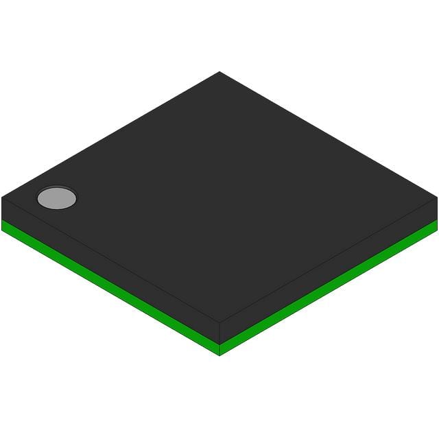
- Part No.:
- DS90CF386SLCX/NOPB
- Manufacturer:
- Texas Instruments
- Category:
- Specialized
- Package:
- 64-LFBGA
- Datasheet:
-
 DS90CF386SLCX/NOPB.pdf
- Description:
- IC INTFACE SPECIALIZED 64NFBGA
- Quantity:
- Payment:

- Shipping:

Inventory:4,316
Please send an inquiry. Send us your inquiry, and we will respond immediately.
Product details
Overview
DS90CF386SLCX/NOPB from Texas Instruments is a 28-bit LVDS-to-LVCMOS deserializer IC used as the receiver in FPD-Link I flat-panel display interfaces. It converts four 140–595 Mbps LVDS data streams and one 20–85 MHz LVDS clock into 28 parallel LVCMOS outputs (24-bit RGB + 4 control signals), operates with <142 mW typical power at 85 MHz, supports VGA/SXGA displays, and features an internal PLL requiring no external components.
For engineers reviewing the DS90CF386SLCX/NOPB datasheet, DS90CF386SLCX/NOPB pinout, DS90CF386SLCX/NOPB application, or DS90CF386SLCX/NOPB equivalent, key selection criteria include LVDS input count (4 data + 1 clock), 28-bit parallel output mapping, TSSOP-56 package compatibility, power-down mode behavior, and FPD-Link I timing compliance up to 85 MHz.
Technical Context
The DS90CF386SLCX/NOPB implements a dedicated FPD-Link I receiver architecture with five differential LVDS inputs (four data lanes + one clock lane), an internal PLL that locks to incoming LVDS clock frequencies from 20 MHz to 85 MHz, and a serial-to-parallel converter that recovers 7 bits per lane per clock cycle for a total of 28 LVCMOS outputs.
Its functional block includes LVDS receivers with 100-Ω differential termination support, a jitter-sensitive PLL optimized for low-noise VCC bypassing, and LVCMOS drivers strobing on the falling edge of RxCLKOUT. The device supports both grayscale and worst-case toggling patterns, with defined skew margins (290 ps at 85 MHz) and setup/hold times referenced to RxCLKOUT.
Key Specifications
| Parameter | Value and Actual Design Meaning |
|---|---|
| Input Standard | TIA/EIA-644 LVDS compliant; requires 100-Ω differential termination per LVDS pair |
| Data Width | 28-bit parallel LVCMOS output (24 RGB + 4 control: HSYNC, VSYNC, DE, CNTL) |
| Max Clock Rate | 85 MHz LVDS input clock → enables 2.38 Gbps aggregate throughput (4 × 595 Mbps) |
| Power Consumption | 96–135 mA at 85 MHz (3.3 V); <400 μA in power-down mode |
| ESD Rating | ±7 kV HBM, ±700 V CDM - suitable for handling in standard ESD-controlled environments |
| Operating Temp | –10°C to +70°C ambient - validated for commercial display subsystems |
| Supply Voltage | 3.0 V to 3.6 V - compatible with standard 3.3-V system rails |
Pinout & Package
The DS90CF386SLCX/NOPB is packaged in a 56-pin TSSOP (DGG) with 14.00 mm × 6.10 mm body size and 0.5-mm lead pitch. Pin functions are electrically validated per TI SNLS055J Rev J.
| Pin/Terminal | Circuit Role | Design Meaning |
|---|---|---|
| RxIN0+ / RxIN0− | LVD differential data input pair 0 | Accepts first serialized 7-bit LVDS data stream; requires 100-Ω termination across pins |
| RxIN1+ / RxIN1− | LVD differential data input pair 1 | Accepts second serialized 7-bit LVDS data stream; matched routing critical for skew control |
| RxIN2+ / RxIN2− | LVD differential data input pair 2 | Accepts third serialized 7-bit LVDS data stream; shares LVDS_GND and LVDS_VCC with other LVDS inputs |
| RxIN3+ / RxIN3− | LVD differential data input pair 3 | Accepts fourth serialized 7-bit LVDS data stream; only present on DS90CF386 (not DS90CF366) |
| RxCLKIN+ / RxCLKIN− | LVD differential clock input | Carries recovered 20–85 MHz clock; PLL locks to this signal to generate RxCLKOUT |
| RxCLKOUT | LVCMOS clock output | Falling-edge strobe for all 28 RxOUT signals; period = input clock period; 5.5–9.5 ns delay from RxCLKIN |
| PWR_DWN | Active-low power-down control | Drives all RxOUT low when asserted; draws <400 μA in shutdown state |
| RxOUT[0:27] | LVCMOS parallel data outputs | 28 single-ended outputs mapped per Figure 8; strobed on RxCLKOUT falling edge; can be left floating if unused |
| VCC / GND / LVDS_VCC / LVDS_GND / PLL_VCC / PLL_GND | Power and ground domains | Separate supplies isolate LVCMOS outputs (VCC), LVDS inputs (LVDS_VCC), and PLL (PLL_VCC) to minimize noise coupling |
Key Features
| Feature | Design Value |
|---|---|
| Integrated PLL | Locks to 20–85 MHz LVDS clock without external components; enables deterministic sampling of serialized data |
| 4-data-lane support | Distinguishes DS90CF386 from DS90CF366 (3-lane); enables 24-bit RGB + 4 control signal transport |
| Falling-edge strobe | RxCLKOUT falling edge clocks all 28 RxOUT outputs - ensures timing alignment with FPD-Link I transmitters |
| Low-power operation | 142 mW typical at 85 MHz grayscale; <1.44 mW max in power-down mode - reduces thermal load in compact displays |
| Dedicated power domains | Independent VCC, LVDS_VCC, and PLL_VCC pins allow localized decoupling to suppress supply noise affecting PLL jitter |
Applications
| Embedded LCD Timing Interface | Industrial Panel PC Video Link |
|---|---|
Use Scenario: Connecting GPU output to a 24-bit RGB TFT panel over flexible cable in space-constrained medical or test equipment. IC Role / Device Role / Timing Role: DS90CF386SLCX/NOPB acts as the LVDS deserializer, recovering parallel pixel data and sync signals from serialized FPD-Link I stream. Use Value: Replaces wide 28-wire parallel interface with 10-wire LVDS (4 data + 1 clock pairs), reducing EMI and connector footprint by >60%. | Use Scenario: Transmitting high-resolution video from a ruggedized controller board to a sunlight-readable display in factory automation. IC Role / Device Role / Timing Role: DS90CF386SLCX/NOPB receives serialized video at up to 85 MHz, providing synchronized 24-bit RGB and DE/HSYNC/VSYNC to the display driver ASIC. Use Value: Enables reliable 1024×768 (XGA) or 1280×1024 (SXGA) transmission over 1+ meter twisted-pair cable with 290 ps skew margin. |
| Open LDI-to-RGB Bridge | Digital Copier Imaging Path |
Use Scenario: Converting legacy LVDS Display Interface (LDI) signals from imaging ASICs to standard RGB timing for panel integration. IC Role / Device Role / Timing Role: DS90CF386SLCX/NOPB serves as protocol-transparent bridge, reconstructing parallel RGB+control from LDI-compliant serial stream. Use Value: Eliminates need for custom FPGA logic; supports direct drop-in replacement of older deserializers in LDI-based copier platforms. | Use Scenario: Routing scanned image data from CIS sensor array to print engine controller in high-speed digital copiers. IC Role / Device Role / Timing Role: DS90CF386SLCX/NOPB deserializes high-bandwidth image data (up to 2.38 Gbps) while maintaining precise pixel clock alignment. Use Value: Maintains <1 ns inter-lane skew tolerance across full 28-bit bus, preserving grayscale fidelity in 600+ DPI output. |
Equivalent & Alternatives
The following parts are listed as comparable options for similar LVDS deserializer applications.
| Alternative Part | Technical Difference | Application Difference | Selection Advice |
|---|---|---|---|
| DS90CF366MTDX/NOPB | 21-bit output (18 RGB + 3 control), 3 LVDS data lanes, 48-pin TSSOP only | Suitable for 18-bit RGB panels (e.g., SVGA, some XGA); lacks CNTL bit and one data lane | Select when panel resolution and color depth require only 18-bit RGB and system layout favors smaller 48-pin footprint |
| SN65LVDS32PW | Quad LVDS receiver only - no deserialization, PLL, or parallel outputs; 16-pin TSSOP | Requires external logic/FPGA to reconstruct parallel data; no clock recovery or timing generation | Choose only for simple LVDS signal conditioning where full FPD-Link I deserialization is handled elsewhere |
Compared with DS90CF366MTDX/NOPB, DS90CF386SLCX/NOPB adds 7-bit data capacity and CNTL signal support for 24-bit RGB panels; compared with SN65LVDS32PW, it integrates full deserialization and clock recovery - eliminating external logic and reducing BOM count by ≥3 components.
Availability
DS90CF386SLCX/NOPB is available at Aetrix Electronics and suitable for embedded LCD timing interfaces, industrial panel PC video links, and open LDI-to-RGB bridge designs requiring stable component supply and long-term display subsystem continuity.
Supply support for DS90CF386SLCX/NOPB includes scheduled delivery planning, volume procurement assistance, BOM continuity management, traceable sourcing, and lifecycle availability coordination for OEM customers, industrial embedded developers, connected-device designers, and electronics production programs.
Manufacturer
Texas Instruments is a global semiconductor leader specializing in analog, embedded processing, and connectivity technologies with broad industrial and automotive design-in support.
The DS90CF386SLCX/NOPB belongs to TI's FPD-Link I serializer/deserializer product line, engineered specifically for cost-sensitive, high-reliability flat-panel display interconnects in commercial and industrial equipment.
FAQ
What is the maximum data rate supported by DS90CF386SLCX/NOPB?
The DS90CF386SLCX/NOPB supports an LVDS clock input up to 85 MHz, resulting in a per-lane bit rate of 595 Mbps and an aggregate throughput of 2.38 Gbps across four data lanes. This enables full 24-bit RGB + 4 control signal transmission for resolutions up to SXGA (1280×1024) at 60 Hz. The DS90CF386SLCX/NOPB datasheet specifies timing margins and skew tolerance validated at this maximum rate.
Does DS90CF386SLCX/NOPB require external components for PLL operation?
No, the DS90CF386SLCX/NOPB contains a fully integrated PLL that locks to the incoming LVDS clock without requiring external capacitors, resistors, or crystal references. The PLL is designed to operate across the full 20–85 MHz input range and generates the RxCLKOUT signal internally. External 100-Ω differential termination resistors are required on each LVDS input pair, but no PLL-specific components are needed.
How does the power-down mode function on DS90CF386SLCX/NOPB?
Asserting the PWR_DWN pin low places the DS90CF386SLCX/NOPB into power-down mode, reducing supply current to <400 μA while driving all RxOUT pins low. The device retains its configuration and exits power-down synchronously upon PWR_DWN deassertion, with PLL lock reacquired within 10 ms. This mode is intended for display blanking or system sleep states where active video is suspended but fast resume is required.
What package options are available for DS90CF386SLCX/NOPB?
The DS90CF386SLCX/NOPB is offered in a 56-pin TSSOP (DGG) package with 14.00 mm × 6.10 mm body size and 0.5-mm lead pitch. While the DS90CF386 family also includes an NFBGA variant (NZC, 64-pin), the DS90CF386SLCX/NOPB suffix specifically denotes the TSSOP-56 version. No SOIC, QFP, or other package variants exist for this orderable part number.
Can DS90CF386SLCX/NOPB interface directly with standard LVCMOS display controllers?
Yes, the DS90CF386SLCX/NOPB provides 28 LVCMOS-compatible outputs (RxOUT[0:27]) with VOH ≥ 2.7 V and VOL ≤ 0.3 V at 3.3 V supply, meeting standard 3.3-V LVCMOS voltage thresholds. Its RxCLKOUT falling edge serves as the synchronous strobe for all outputs, aligning with common display controller sampling requirements. No level-shifting or timing translation is needed when interfacing with FPGA-, ASIC-, or MCU-based RGB display interfaces.
DS90CF386SLCX/NOPB Specifications
- Product attributes
- Attribute value
- Manufacturer:
- Texas Instruments
- Series:
- -
- Package/Case:
- 64-LFBGA
- Packaging:
- Tape & Reel (TR)
- Product Status:
- Active
- Applications:
- -
- Interface:
- -
- Voltage - Supply:
- 3V ~ 3.6V
- Supplier Device Package:
- 64-NFBGA (8x8)
- Grade:
- -
- Qualification:
- -
- Mounting Type:
- Surface Mount
DS90CF386SLCX/NOPB FAQ
1.How can I place an order for DS90CF386SLCX/NOPB through Aetrix?
Please submit a Request for Quotation (RFQ) for DS90CF386SLCX/NOPB on Aetrix. Our sales agent will provide a competitive quotation and guide you through the order confirmation once you accept the terms.
2.Are the price and stock information for DS90CF386SLCX/NOPB reliable?
The price and inventory of DS90CF386SLCX/NOPB are updated periodically and may fluctuate due to market conditions. Stock and pricing data are typically refreshed every 24 hours. Quotation validity for DS90CF386SLCX/NOPB is usually 5 days.
3.What payment methods are accepted for DS90CF386SLCX/NOPB?
We accept Wire Transfer, PayPal, Credit Card, Western Union, MoneyGram, and Escrow for DS90CF386SLCX/NOPB transactions.
Note: Certain payment methods may incur a processing fee.
4.How is shipping managed for DS90CF386SLCX/NOPB?
DS90CF386SLCX/NOPB orders can be shipped via leading logistics carriers, including DHL, UPS, FedEx, TNT, or Registered Mail.
Once your DS90CF386SLCX/NOPB order is processed, you will receive an email with the shipment details and tracking number.
Note: Tracking information may take up to 24 hours to appear. Express delivery typically takes 3–5 business days.
5.How can I obtain technical support or documentation for DS90CF386SLCX/NOPB?
For technical support, including DS90CF386SLCX/NOPB datasheets, pinout diagrams, or application guidance, please contact our engineering support team. They can provide detailed documentation and assistance for your DS90CF386SLCX/NOPB requirements.
6.How does Aetrix verify that DS90CF386SLCX/NOPB is sourced from the original manufacturer or authorized distributors?
All DS90CF386SLCX/NOPB products on Aetrix are procured from qualified distributors and authorized channels. Our dedicated quality assurance team conducts strict verification, including traceability checks and, if necessary, third-party testing. This ensures that DS90CF386SLCX/NOPB meets industry standards.
7.What is the process for return or replacement of DS90CF386SLCX/NOPB?
All DS90CF386SLCX/NOPB units undergo pre-shipment inspection (PSI). If there is an issue with DS90CF386SLCX/NOPB, returns or replacements are accepted under the following conditions:
1.Quantity discrepancies, incorrect items, or visible external defects (such as breakage or corrosion), acknowledged by Aetrix.
2.The issue is reported within 90 days of delivery.
3.The DS90CF386SLCX/NOPB part is unused and in its original packaging.
Return procedure for DS90CF386SLCX/NOPB:
1.Submit a request within 90 days.
2.Obtain a Return Material Authorization (RMA) from Aetrix.
DS90CF386SLCX/NOPB Tags

-
NVT4857UKAZ
NXP Semiconductors

-
TCA8418RTWR
Texas Instruments

-
PCA9546APWR
Texas Instruments

-
MD0100N8-G
Microchip Technology

-
PCA9548APW,118
NXP Semiconductors

-
PCA9540BDP,118
NXP Semiconductors

-
PCA9548APWR
Texas Instruments

-
PCA9546APW,118
NXP Semiconductors

-
PTN3360DBS,518
NXP Semiconductors

-
PCA9546ABS,118
NXP Semiconductors

-
PCA9518PWR
Texas Instruments

-
PCA9545APW,118
NXP Semiconductors
Tech Hub

A practical engineering guide to 3.3V and 5V logic compatibility, input thresholds, resistor dividers, translator ICs, MOSFET level shifting, I2C pull-ups, timing limits and power-sequencing risks.

The 74HC595 uses push-pull logic outputs, while the TPIC6B595 uses 50 V open-drain DMOS sinks for higher-power loads. This guide compares timing, current limits, 3.3 V interfacing, load wiring, thermal…

The 74HC595 converts serial data into eight stable parallel outputs. This guide covers pin functions, shift and storage timing, OE and MR behavior, drive-current limits, cascading, voltage compatibilit…

A technical comparison of level-sensitive latches and edge-triggered flip-flops, covering timing windows, setup and hold limits, master–slave operation, time borrowing, race-through, HDL inference and…

A D latch stores one bit while Enable controls when data can pass. This reference covers gate-level operation, truth tables, transparency, setup and hold timing, LE versus OE, common ICs and practical …

An SR latch stores one bit through cross-coupled feedback. This engineering reference covers NOR and NAND implementations, truth tables, forbidden-state recovery, gated operation, switch debouncing, fa…

Latch circuits retain one bit through feedback. This technical reference covers SR and D latches, truth tables, transparency, timing limits, latch-versus-flip-flop behavior, applications and common log…

An engineering guide to LED driver operation, constant-current and constant-voltage outputs, linear and switching topologies, dimming, IC selection, calculations, replacement compatibility, and fault c…

Operational amplifier guide covering op amp basics, feedback, ideal vs real op amps, common configurations, buffer circuits, offset, bias current, gain-bandwidth, slew rate, rail-to-rail limits and sel…

Jumper cables guide covering safe connection order, red and black clamp placement, final ground connection, cable gauge, length, clamp quality, copper vs CCA cables, jump starter comparison and battery…


