
 My Inquiry
 My Account


Texas Instruments DS90CF388VJD/NOPB
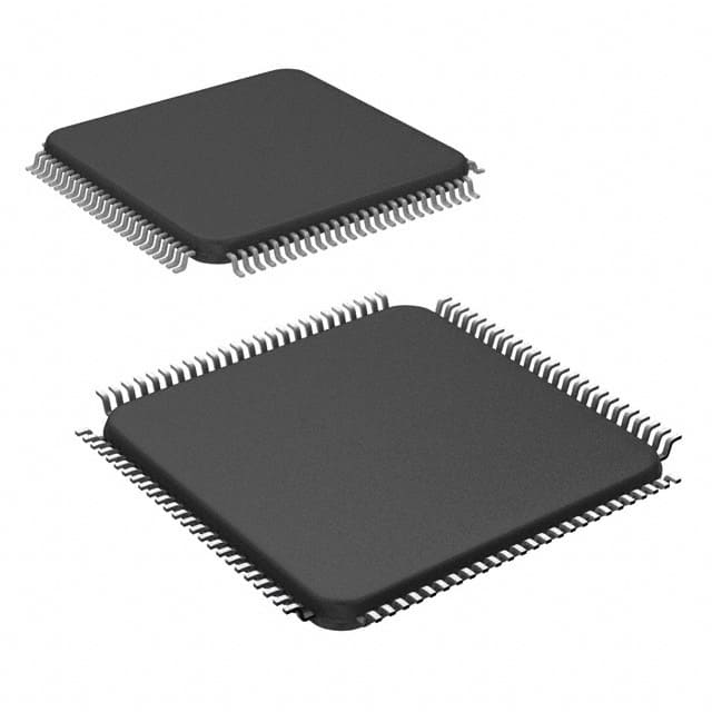
- Part No.:
- DS90CF388VJD/NOPB
- Manufacturer:
- Texas Instruments
- Category:
- Specialized
- Package:
- 100-TQFP
- Datasheet:
-
 DS90CF388VJD/NOPB.pdf
- Description:
- IC INTERFACE SPECIALIZED 100TQFP
- Quantity:
- Payment:

- Shipping:

Inventory:1,532
Please send an inquiry. Send us your inquiry, and we will respond immediately.
Product details
Overview
DS90CF388VJD/NOPB from Texas Instruments is a dual-pixel LVDS display interface receiver IC designed for high-resolution flat-panel displays up to QXGA (2048×1536). It converts eight LVDS data streams and one LVDS clock into 48-bit parallel CMOS/TTL RGB output with embedded control signals (HSYNC, VSYNC, DE), supporting 40–112 MHz pixel clock rates and delivering up to 5.38 Gbps total bandwidth in dual-pixel mode. It operates from a 3.3 V supply and features DC-balanced deserialization, cable deskew, and programmable strobe edge selection.
For engineers reviewing the DS90CF388VJD/NOPB datasheet, DS90CF388VJD/NOPB pinout, DS90CF388VJD/NOPB application, or DS90CF388VJD/NOPB equivalent, key selection considerations include its 112 MHz dual-pixel clock support, ±1 LVDS bit-time deskew capability (up to 80 MHz), DC-balance auto-detection, 5 V-tolerant TTL outputs, and compatibility with OpenLDI-compliant transmitter pairs such as DS90C387.
Technical Context
The DS90CF388VJD/NOPB implements a PLL-based LVDS-to-TTL deserializer with automatic DC-balance detection: when BAL = HIGH, it identifies whether incoming data originates from a DC-balanced (DS90C387) or legacy non-DC-balanced source and applies appropriate bit mapping. Its DESKEW function-enabled only in DC-balance mode-adjusts sampling strobes to compensate for pair-to-pair skew up to ±1 LVDS bit time.
It supports three operational modes via the DUAL pin: dual-pixel (48-bit input → 48-bit output), single-pixel (24-bit input → 48-bit output), and single-in/dual-out conversion. The receiver provides TTL-level outputs with 2.7 V VOH at −0.4 mA, 0.3 V VOL at 2 mA, and sub-2 ns CMOS/TTL transition times, while rejecting cycle-to-cycle jitter ≤100 ps at 112 MHz.
Key Specifications
| Parameter | Value and Actual Design Meaning |
|---|---|
| Function | LVDS-to-CMOS/TTL display interface receiver for dual-pixel flat-panel applications |
| Pixel Clock Range | 40–112 MHz - enables QXGA resolution at full dual-pixel rate (112 MHz × 48 bits = 5.38 Gbps) |
| LVDS Inputs | 8 differential data pairs + 1 differential clock pair - matches DS90C387 transmitter output configuration |
| Parallel Output | 48-bit RGB (16R/16G/16B) + HSYNC/VSYNC/DE - TTL-compatible with 5 V tolerance on all I/O pins |
| Deskew Capability | ±1 LVDS bit time (e.g., ±8.9 ns at 112 MHz) - corrects inter-pair skew on long cables without external calibration |
| DC Balance Support | Auto-detect mode (BAL = HIGH) - dynamically selects correct deserialization mapping for DS90C387 or legacy FPD-Link sources |
| Power Supply | 3.3 V nominal (3.0–3.6 V) - compatible with standard LVDS interface power domains |
Pinout & Package
DS90CF388VJD/NOPB is housed in a 100-pin TQFP (Thin Quad Flat Package) with 0.5 mm pitch, thermally enhanced for display interface applications requiring stable operation at up to +70°C ambient.
| Pin/Terminal | Circuit Role | Design Meaning |
|---|---|---|
| AnP[0:7] | LVDS positive data inputs | Accepts 8 differential LVDS data channels from DS90C387; mapped per OpenLDI bit naming convention (RO0–BO7, RE0–BE7) |
| AnM[0:7] | LVDS negative data inputs | Differential complements to AnP[0:7]; required for noise-immune high-speed serial reception |
| RxCLK INP / RxCLK INM | LVDS clock input pair | Receives serialized clock from transmitter; used for PLL lock and internal timing recovery |
| Rn/Gn/Bn[0:15], DE, HSYNC, VSYNC | TTL-level parallel outputs | 48-bit RGB + 3 control signals; 5 V tolerant, 2.7 V VOH min at −0.4 mA load |
| RxCLK OUT | TTL clock output | Falling-edge strobe synchronized to recovered pixel clock; drives downstream timing controller |
| BAL | Mode select input | HIGH enables auto-detect DC-balance mode; LOW forces legacy non-DC-balanced deserialization |
| DESKEW | Deskew enable input | HIGH activates intra-receiver sampling adjustment to compensate for LVDS pair skew (requires BAL = HIGH) |
| PD | Power-down control | LOW places outputs in low state and disables internal circuitry; draws ≤300 µA quiescent current |
| VCC / GND / LVDSVCC / LVDSGND / PLLVCC / PLLGND | Supply and ground terminals | Separate power domains isolate digital logic (VCC), LVDS receivers (LVDSVCC), and PLL (PLLVCC) to minimize noise coupling |
Key Features
| Feature | Design Value |
|---|---|
| Auto-detect DC-balance deserialization | Eliminates manual configuration: DS90CF388VJD/NOPB senses DS90C387's DC-balanced encoding and applies correct bit mapping without external control |
| Cable deskew with ±1 bit-time correction | Compensates for inter-pair skew on cables ≥5 m long at up to 80 MHz clock rates, enabling robust transmission over low-cost twisted-pair |
| Programmable data/control strobe edge | R_FDE pin selects rising or falling edge for DE strobe synchronization, matching diverse timing controller requirements |
| Backward compatibility with FPD-Link | Supports legacy single-pixel and non-DC-balanced interfaces via DUAL and BAL pin configuration, easing migration from older designs |
| 5 V-tolerant TTL I/O | Allows direct connection to 5 V logic without level shifters, simplifying integration with legacy display timing controllers and GUI processors |
Applications
| QXGA Medical Imaging Display | Industrial HMI Panel Interface |
|---|---|
Use Scenario: High-resolution diagnostic monitor driving 2048×1536 LCD panel with real-time image streaming from FPGA-based acquisition system. IC Role / Device Role / Timing Role: Receives serialized dual-pixel LVDS stream from DS90C387 transmitter; recovers clock and deserializes into 48-bit RGB with precise DE/HSYNC alignment. Use Value: Enables 112 MHz pixel clock operation with <100 ps cycle-to-cycle jitter rejection, ensuring artifact-free rendering of critical medical imagery. |
Use Scenario: Ruggedized factory-floor HMI using 1280×1024 SVGA panel connected via 4-meter shielded twisted-pair cable. IC Role / Device Role / Timing Role: LVDS receiver with active deskew compensating for 350 ps inter-pair skew induced by cable length and EMI. Use Value: Maintains valid data eye at receiver input under industrial EMI conditions, eliminating need for expensive coaxial or shielded ribbon solutions. |
| Automotive Digital Instrument Cluster | Avionics Multi-Function Display |
Use Scenario: Next-generation automotive cluster displaying vector-rendered gauges and ADAS alerts on 1920×720 wide-format TFT. IC Role / Device Role / Timing Role: Converts dual-pixel LVDS from SoC graphics engine into parallel RGB with embedded VSYNC/HSYNC for seamless frame sync. Use Value: 5 V-tolerant outputs interface directly to panel timing controller; DC-balance auto-detect ensures compatibility across multiple SoC generations. |
Use Scenario: MIL-STD-810-certified cockpit display receiving graphics from safety-critical flight management unit. IC Role / Device Role / Timing Role: Receives LVDS video with guaranteed setup/hold margins (RSKM ≥300 ps at 85 MHz) and failsafe power-down behavior. Use Value: Power-down mode reduces current to ≤300 µA while holding outputs low-critical for deterministic fault containment during reset sequences. |
Equivalent & Alternatives
The following parts are listed as comparable options for similar LVDS display receiver applications.
| Alternative Part | Technical Difference | Application Difference | Selection Advice |
|---|---|---|---|
| DS90CF386VJD/NOPB | Lower clock range (35–85 MHz); no DESKEW or DC-balance auto-detect; 36-bit RGB output only | Supports only SXGA (1280×1024) and below; unsuitable for QXGA or long-cable (>3 m) deployments | Select when cost sensitivity outweighs resolution and cable-length requirements; verify timing controller compatibility with fixed 36-bit output |
| SN65LVDS32PW | Single-channel LVDS receiver (4-bit); no deserialization, no PLL, no RGB output - only LVDS-to-TTL level translation | Requires external FPGA or ASIC for deserialization and pixel mapping; not a drop-in replacement | Use only as building block in custom serializer/receiver architecture; not suitable for direct display interface replacement |
Compared with DS90CF388VJD/NOPB, DS90CF386VJD/NOPB sacrifices QXGA support and cable robustness for lower BOM cost, while SN65LVDS32PW lacks integrated deserialization entirely-making both alternatives non-substitutable without significant redesign.
Availability
DS90CF388VJD/NOPB is available at Aetrix Electronics and suitable for high-resolution display interfaces in medical imaging systems, industrial HMIs, automotive instrument clusters, and avionics MFDs requiring stable component supply and long-term production continuity.
Supply support for DS90CF388VJD/NOPB includes scheduled delivery planning, volume procurement assistance, BOM continuity management, traceable sourcing, and lifecycle availability coordination for OEM customers, industrial embedded developers, connected-device designers, and electronics production programs.
Manufacturer
Texas Instruments is a global semiconductor leader specializing in analog, embedded processing, and connectivity technologies, with decades of leadership in display interface solutions.
The DS90CF388VJD/NOPB belongs to TI's OpenLDI-compliant LDI chipset family, engineered specifically for high-bandwidth, low-EMI digital display links between host processors and flat-panel displays in demanding commercial and industrial environments.
FAQ
What is the maximum supported pixel clock frequency for DS90CF388VJD/NOPB in dual-pixel mode?
The DS90CF388VJD/NOPB supports a maximum pixel clock frequency of 112 MHz in dual-pixel mode, enabling QXGA (2048×1536) resolution at 60 Hz refresh rate with full 48-bit color depth. This is confirmed in the Electrical Characteristics table under "Receiver Switching Characteristics" for RCOP (RxCLK OUT Period) and verified in the Functional Description section stating "40 to 112MHz Clock Support for DS90CF388".
Does DS90CF388VJD/NOPB require an external crystal or reference clock?
No, DS90CF388VJD/NOPB does not require an external crystal or reference clock. It recovers timing directly from the incoming LVDS clock pair (RxCLK INP/RxCLK INM) using an internal PLL, as specified in the Receiver Block Diagram and confirmed in the "Receiver Phase Lock Loop Set" timing parameter (RPLLS = 10 ms).
How does DS90CF388VJD/NOPB handle DC balance detection and what is required to enable it?
DS90CF388VJD/NOPB enables automatic DC-balance detection when the BAL pin is driven HIGH. In this mode, it analyzes the incoming LVDS data stream to determine whether it originates from a DC-balanced DS90C387 or a legacy non-DC-balanced source, then applies the correct deserialization mapping per Tables 3 and 4 of the datasheet. No external configuration or firmware is needed.
Can DS90CF388VJD/NOPB drive a display panel directly, or does it require a separate timing controller?
DS90CF388VJD/NOPB outputs parallel TTL-level RGB data and control signals (HSYNC, VSYNC, DE), but it does not generate panel-specific timing such as gate/source driver clocks or power sequencing. It must be paired with a dedicated display timing controller (TCON) that accepts these signals and drives the TFT panel's row/column drivers accordingly.
What is the purpose of the DESKEW pin on DS90CF388VJD/NOPB and under what conditions does it operate?
The DESKEW pin on DS90CF388VJD/NOPB enables cable deskew functionality, which adjusts internal sampling strobes to compensate for pair-to-pair skew in the LVDS interconnect. It operates only when BAL = HIGH (DC-balance mode enabled) and requires ≥4 clock cycles during vertical/horizontal blanking intervals to complete calibration, as documented in the Pin Descriptions and Figure 13 (RSKMD).
DS90CF388VJD/NOPB Specifications
- Product attributes
- Attribute value
- Manufacturer:
- Texas Instruments
- Series:
- -
- Package/Case:
- 100-TQFP
- Packaging:
- Tray
- Product Status:
- Active
- Applications:
- -
- Interface:
- -
- Voltage - Supply:
- 3V ~ 3.6V
- Supplier Device Package:
- 100-TQFP (14x14)
- Grade:
- -
- Qualification:
- -
- Mounting Type:
- Surface Mount
DS90CF388VJD/NOPB FAQ
1.How can I place an order for DS90CF388VJD/NOPB through Aetrix?
Please submit a Request for Quotation (RFQ) for DS90CF388VJD/NOPB on Aetrix. Our sales agent will provide a competitive quotation and guide you through the order confirmation once you accept the terms.
2.Are the price and stock information for DS90CF388VJD/NOPB reliable?
The price and inventory of DS90CF388VJD/NOPB are updated periodically and may fluctuate due to market conditions. Stock and pricing data are typically refreshed every 24 hours. Quotation validity for DS90CF388VJD/NOPB is usually 5 days.
3.What payment methods are accepted for DS90CF388VJD/NOPB?
We accept Wire Transfer, PayPal, Credit Card, Western Union, MoneyGram, and Escrow for DS90CF388VJD/NOPB transactions.
Note: Certain payment methods may incur a processing fee.
4.How is shipping managed for DS90CF388VJD/NOPB?
DS90CF388VJD/NOPB orders can be shipped via leading logistics carriers, including DHL, UPS, FedEx, TNT, or Registered Mail.
Once your DS90CF388VJD/NOPB order is processed, you will receive an email with the shipment details and tracking number.
Note: Tracking information may take up to 24 hours to appear. Express delivery typically takes 3–5 business days.
5.How can I obtain technical support or documentation for DS90CF388VJD/NOPB?
For technical support, including DS90CF388VJD/NOPB datasheets, pinout diagrams, or application guidance, please contact our engineering support team. They can provide detailed documentation and assistance for your DS90CF388VJD/NOPB requirements.
6.How does Aetrix verify that DS90CF388VJD/NOPB is sourced from the original manufacturer or authorized distributors?
All DS90CF388VJD/NOPB products on Aetrix are procured from qualified distributors and authorized channels. Our dedicated quality assurance team conducts strict verification, including traceability checks and, if necessary, third-party testing. This ensures that DS90CF388VJD/NOPB meets industry standards.
7.What is the process for return or replacement of DS90CF388VJD/NOPB?
All DS90CF388VJD/NOPB units undergo pre-shipment inspection (PSI). If there is an issue with DS90CF388VJD/NOPB, returns or replacements are accepted under the following conditions:
1.Quantity discrepancies, incorrect items, or visible external defects (such as breakage or corrosion), acknowledged by Aetrix.
2.The issue is reported within 90 days of delivery.
3.The DS90CF388VJD/NOPB part is unused and in its original packaging.
Return procedure for DS90CF388VJD/NOPB:
1.Submit a request within 90 days.
2.Obtain a Return Material Authorization (RMA) from Aetrix.
DS90CF388VJD/NOPB Tags

-
NVT4857UKAZ
NXP Semiconductors

-
TCA8418RTWR
Texas Instruments

-
PCA9546APWR
Texas Instruments

-
MD0100N8-G
Microchip Technology

-
PCA9548APW,118
NXP Semiconductors

-
PCA9540BDP,118
NXP Semiconductors

-
PCA9548APWR
Texas Instruments

-
PCA9546APW,118
NXP Semiconductors

-
PTN3360DBS,518
NXP Semiconductors

-
PCA9546ABS,118
NXP Semiconductors

-
PCA9518PWR
Texas Instruments

-
PCA9545APW,118
NXP Semiconductors
Tech Hub

A practical engineering guide to 3.3V and 5V logic compatibility, input thresholds, resistor dividers, translator ICs, MOSFET level shifting, I2C pull-ups, timing limits and power-sequencing risks.

The 74HC595 uses push-pull logic outputs, while the TPIC6B595 uses 50 V open-drain DMOS sinks for higher-power loads. This guide compares timing, current limits, 3.3 V interfacing, load wiring, thermal…

The 74HC595 converts serial data into eight stable parallel outputs. This guide covers pin functions, shift and storage timing, OE and MR behavior, drive-current limits, cascading, voltage compatibilit…

A technical comparison of level-sensitive latches and edge-triggered flip-flops, covering timing windows, setup and hold limits, master–slave operation, time borrowing, race-through, HDL inference and…

A D latch stores one bit while Enable controls when data can pass. This reference covers gate-level operation, truth tables, transparency, setup and hold timing, LE versus OE, common ICs and practical …

An SR latch stores one bit through cross-coupled feedback. This engineering reference covers NOR and NAND implementations, truth tables, forbidden-state recovery, gated operation, switch debouncing, fa…

Latch circuits retain one bit through feedback. This technical reference covers SR and D latches, truth tables, transparency, timing limits, latch-versus-flip-flop behavior, applications and common log…

An engineering guide to LED driver operation, constant-current and constant-voltage outputs, linear and switching topologies, dimming, IC selection, calculations, replacement compatibility, and fault c…

Operational amplifier guide covering op amp basics, feedback, ideal vs real op amps, common configurations, buffer circuits, offset, bias current, gain-bandwidth, slew rate, rail-to-rail limits and sel…

Jumper cables guide covering safe connection order, red and black clamp placement, final ground connection, cable gauge, length, clamp quality, copper vs CCA cables, jump starter comparison and battery…


