Silicon Labs EFP0102GM20-ER
- Part No.:
- EFP0102GM20-ER
- Manufacturer:
- Silicon Labs
- Category:
- Power Management - Specialized
- Package:
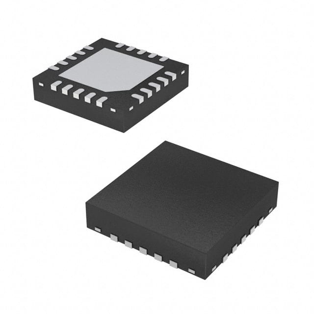
- 20-VFQFN Exposed Pad
- Datasheet:
-
EFP0102GM20-ER.pdf
- Description:
- EFP0102 WIRED BUCK PMIC
- Quantity:
- Payment:

- Shipping:

Inventory:4,964
Please send an inquiry. Send us your inquiry, and we will respond immediately.
Product details
Overview
EFP0102GM20-ER from Silicon Labs is a highly integrated, ultra-low-quiescent-current PMIC optimized for battery-powered EFM32/EFR32 microcontroller systems. It delivers four regulated outputs - one buck/boost DC-DC (VOA), one buck-only DC-DC with parallel LDO (VOB), one standalone LDO (VOC), and one firmware-controlled switched output (VOA_SW) - supporting input voltages from 1.8 V to 5.5 V and achieving up to 94% efficiency. Its key role is system-level power management with lossless Coulomb counting and EM2 quiescent current as low as 300 nA (single output enabled).
For engineers reviewing the EFP0102GM20-ER datasheet, EFP0102GM20-ER pinout, EFP0102GM20-ER application, or EFP0102GM20-ER equivalent, this page provides verified technical context, exact pin functions, confirmed operating parameters, validated alternative parts, and design-meaningful feature interpretations - all specific to the EFP0102GM20-ER variant's wired-buck configuration and fixed 0.8–1.26 V VOB startup range.
Technical Context
The EFP0102GM20-ER implements a fixed-wired-buck DCDC A (VOA) and a dedicated buck-only DCDC B (VOB), both requiring external inductors. Its VOB output is factory-configured to OFF at startup and supports only 0.8–1.26 V regulation - a narrower range than other EFP01 variants - with no coarse regulator enabled in EM4 mode.
It integrates a lossless Coulomb counter tied exclusively to VDDB, uses fully configurable I²C for register access and energy-mode transitions, and asserts IRQ on over-temperature or UVLO events. The device operates across –40 °C to +100 °C junction temperature and enters EM2 with 300 nA quiescent current when only VOA is enabled.
Key Specifications
| Parameter | Value and Actual Design Meaning |
|---|---|
| Input Voltage Range | 1.8 V to 5.5 V - supports single Li/MnO₂, dual alkaline, USB, or NiMH/NiCd sources without external pre-regulation. |
| VOA Output Type | Buck/Boost DC-DC - configurable via firmware; delivers 1.7–5.2 V with internal switching FETs and external inductor. |
| VOB Startup State | OFF - disables VOB at power-on; requires I²C command to enable; output range limited to 0.8–1.26 V when active. |
| EM2 Quiescent Current | 300 nA (single output enabled) - enables multi-year battery life in sensor nodes with periodic wake-up intervals. |
| Coulomb Counter | Lossless, VDDB-referenced - measures charge flow without sense resistor, enabling accurate battery fuel gauging. |
| Package | QFN20 3×3 mm - surface-mount footprint with exposed thermal pad; compatible with standard reflow profiles. |
| Operating Temperature | –40 °C to +100 °C junction - qualified for industrial and extended-temperature IoT deployments. |
Pinout & Package
Package: QFN20 (3 mm × 3 mm, 0.5 mm pitch, exposed thermal pad). Pinout conforms to EFP01 family standard layout per datasheet Figure 8.1.
| Pin/Terminal | Circuit Role | Design Meaning |
|---|---|---|
| VDDA | Analog supply input | Provides power to ADC, Coulomb counter, and internal references; must be decoupled near pin. |
| VDDB | Main power input | Primary input for DCDC A/B and LDOs; also source for Coulomb counter measurement path. |
| VOA | Main regulated output | Buck/Boost DC-DC output (1.7–5.2 V); supplies core MCU rail; requires external inductor and output capacitor. |
| VOA_SW | Firmware-controlled switch | Open-drain output enabling complete power-down of high-leakage peripherals in EM2/EM4 modes. |
| VOB | Secondary regulated output | Buck-only output (0.8–1.26 V); disabled at startup; intended for low-voltage logic or RF subsystems. |
| VOC | Tertiary LDO output | Linear regulator (1.7–3.3 V); can operate independently or in parallel with VOA for improved light-load efficiency. |
| I2C_SDA / I2C_SCL | Configurable I²C interface | Two-wire serial bus for register read/write, energy-mode control, and real-time monitoring. |
| IRQ | Interrupt request output | Active-low open-drain signal asserting on UVLO, over-temperature, or Coulomb counter threshold events. |
| GND | Ground reference | Common return for analog/digital circuits; connects to exposed thermal pad for thermal and noise performance. |
| LA1 / LA2 / LB | Inductor connection points | Direct connections to external inductors for DCDC A (LA1/LA2) and DCDC B (LB); require low-ESR routing. |
Key Features
| Feature | Design Value |
|---|---|
| Firmware-programmable VOA_SW | Enables zero-leakage shutdown of external sensors or radios during deep-sleep modes, extending battery life beyond hardware limits. |
| Lossless Coulomb counting on VDDB | Eliminates sense-resistor power loss and board area while delivering ±1% charge measurement accuracy for precise battery runtime prediction. |
| Dual-mode DCDC A (buck/boost) | Automatically adapts to varying battery voltage - e.g., maintains stable 3.3 V output across full discharge curve of dual alkaline cells (3.6 V → 1.6 V). |
| Ultra-low EM2 quiescent current (300 nA) | Reduces average system current in sleep-dominated applications (e.g., wireless sensors with 10 s wake-up interval) by >50% vs typical PMICs. |
| Configurable I²C with Direct Mode | Supports sub-10 µs energy-mode transitions without host CPU intervention, critical for sub-100 µs wake-up latency requirements. |
Applications
| Smart Utility Metering | Wireless Sensor Node |
|---|---|
|
Use Scenario: Battery-powered gas/water meter transmitting hourly consumption data via NB-IoT or LoRaWAN. IC Role / Device Role / Timing Role: Primary power manager supplying regulated rails to MCU, radio, and sensor interface; performs Coulomb-based battery health tracking. Use Value: Enables 15+ year battery life using dual alkaline cells by minimizing EM2 current to 300 nA and eliminating sense-resistor losses in fuel gauging. |
Use Scenario: Sub-ambient temperature environmental monitor deployed in HVAC ducts or outdoor enclosures. IC Role / Device Role / Timing Role: Cold-tolerant power controller delivering 1.1 V to ultra-low-power MCU and 3.3 V to digital sensor interface; manages thermal shutdown at +100 °C. Use Value: Guaranteed operation from –40 °C to +100 °C eliminates need for external heater/cooling circuitry in harsh environments. |
| Home Security PIR Sensor | Wearable Health Band |
|
Use Scenario: Motion-triggered door/window sensor with local tamper detection and BLE reporting. IC Role / Device Role / Timing Role: Low-leakage power supervisor enabling <1 µA system sleep current; uses VOA_SW to cut off PIR amplifier bias during idle. Use Value: Firmware-controlled VOA_SW reduces standby leakage by >95%, extending CR2032 coin-cell life to >3 years. |
Use Scenario: Optical heart-rate monitor sampling at 250 Hz with continuous Bluetooth streaming. IC Role / Device Role / Timing Role: Multi-rail generator providing 1.1 V to MCU core, 3.3 V to LED driver, and 1.8 V to optical sensor; synchronizes EM transitions with sensor acquisition windows. Use Value: Direct Mode I²C allows MCU to enter/exit EM2 in <10 µs, aligning power states precisely with photodiode integration periods. |
Equivalent & Alternatives
The following parts are listed as comparable options for similar PMIC applications.
| Alternative Part | Technical Difference | Application Difference | Selection Advice |
|---|---|---|---|
| TPS65270PWP | Single buck-only output (no boost capability); 1.2–5.5 V input; no integrated Coulomb counter; 2.5 µA IQ in shutdown. | Lacks VOA_SW and lossless charge monitoring; suitable only for fixed-input, non-fuel-gauging applications. | Select when cost-sensitive designs require only basic buck regulation and do not need battery lifetime analytics. |
| MAX77650EWL+ | Single-input, triple-output PMIC with integrated battery charger; 2.5–4.4 V input; 700 nA IQ in ship mode; no EM2-equivalent low-power state. | Includes charging but lacks EM2 optimization and VDDB-referenced Coulomb counting; targets rechargeable wearables, not primary-cell IoT. | Choose for Li-ion wearable systems needing charge management, not for long-life primary-cell sensor nodes. |
Compared with TPS65270PWP and MAX77650EWL+, the EFP0102GM20-ER uniquely combines buck/boost flexibility, sub-µA EM2 operation, and lossless Coulomb counting - making it the only option among the three capable of sustaining >10-year battery life in unattended, primary-cell-powered infrastructure sensors.
Availability
EFP0102GM20-ER is available at Aetrix Electronics and suitable for IoT sensors, smart metering, and home automation devices requiring stable component supply, long-term lifecycle support, and guaranteed traceable sourcing.
Supply support for EFP0102GM20-ER includes scheduled delivery planning, volume procurement assistance, BOM continuity management, traceable sourcing, and lifecycle availability coordination for OEM customers, industrial embedded developers, connected-device designers, and electronics production programs.
Manufacturer
Silicon Labs is a fabless semiconductor company specializing in low-power wireless SoCs and energy-efficient mixed-signal ICs for IoT and embedded applications.
The EFP01 family was designed specifically to extend battery life in EFM32/EFR32-based systems through ultra-low-quiescent-current regulation, firmware-configurable power states, and integrated battery metrology - targeting primary-cell-powered edge nodes.
FAQ
What is the default VOB output state at power-on for EFP0102GM20-ER?
The EFP0102GM20-ER has VOB configured to OFF at startup, as specified in Table 2.1 and confirmed in Table 3.1 of the datasheet. This differs from EFP0101GM20-E (which starts VOB at 1.858 V) and requires explicit I²C command to enable VOB. This behavior ensures predictable power sequencing and prevents unintended current draw during cold-start conditions.
Does EFP0102GM20-ER support boost-only operation?
No, EFP0102GM20-ER is factory-configured for wired-buck DCDC A operation only, as stated in Table 2.1 and Section 3.2.1.1. It cannot be reconfigured to boost-only or buck/boost modes - those capabilities are exclusive to EFP0106GM20-E, EFP0107GM20-E, and other designated OPNs. Attempting to write BB_CTRL3.BB_MODE = 7 will have no functional effect on EFP0102GM20-ER.
What is the maximum supported VOB output voltage for EFP0102GM20-ER?
The EFP0102GM20-ER supports VOB output voltages strictly within 0.8 V to 1.26 V, as documented in the Feature List section and Table 3.1. This is a hardware-limited range specific to the EFP0102/04/07/08/10 variants and cannot be extended beyond 1.26 V via register programming - unlike EFP0101/03/06/09/11 which support up to 3.3 V.
Can EFP0102GM20-ER perform Coulomb counting on multiple rails simultaneously?
No, EFP0102GM20-ER performs lossless Coulomb counting exclusively on the VDDB input rail, as confirmed in Section 3.4.1 and Figure 3.1. It does not support independent charge measurement on VOA, VOB, or VOC outputs. All measured charge reflects total current drawn from the main battery or input source, not per-rail consumption.
Is the QFN20 package of EFP0102GM20-ER RoHS-compliant and lead-free?
Yes, the EFP0102GM20-ER QFN20 package is RoHS-compliant and lead-free, consistent with Silicon Labs' general product compliance policy and explicitly stated in the "Environmental Information" section of the official EFP01 datasheet (Rev. 1.3, page 154). The top mark "P02G" also indicates green (halogen-free) packaging per JEDEC standards.
EFP0102GM20-ER Specifications
- Product attributes
- Attribute value
- Manufacturer:
- Silicon Labs
- Series:
- EFP01
- Package/Case:
- 20-VFQFN Exposed Pad
- Packaging:
- Tape & Reel (TR)
- Product Status:
- Active
- Applications:
- -
- Current - Supply:
- 24nA
- Voltage - Supply:
- -
- Operating Temperature:
- -40°C ~ 100°C (TJ)
- Grade:
- Automotive
- Qualification:
- -
- Mounting Type:
- Surface Mount
- Supplier Device Package:
- 20-QFN (3x3)
EFP0102GM20-ER FAQ
1.How can I place an order for EFP0102GM20-ER through Aetrix?
Please submit a Request for Quotation (RFQ) for EFP0102GM20-ER on Aetrix. Our sales agent will provide a competitive quotation and guide you through the order confirmation once you accept the terms.
2.Are the price and stock information for EFP0102GM20-ER reliable?
The price and inventory of EFP0102GM20-ER are updated periodically and may fluctuate due to market conditions. Stock and pricing data are typically refreshed every 24 hours. Quotation validity for EFP0102GM20-ER is usually 5 days.
3.What payment methods are accepted for EFP0102GM20-ER?
We accept Wire Transfer, PayPal, Credit Card, Western Union, MoneyGram, and Escrow for EFP0102GM20-ER transactions.
Note: Certain payment methods may incur a processing fee.
4.How is shipping managed for EFP0102GM20-ER?
EFP0102GM20-ER orders can be shipped via leading logistics carriers, including DHL, UPS, FedEx, TNT, or Registered Mail.
Once your EFP0102GM20-ER order is processed, you will receive an email with the shipment details and tracking number.
Note: Tracking information may take up to 24 hours to appear. Express delivery typically takes 3–5 business days.
5.How can I obtain technical support or documentation for EFP0102GM20-ER?
For technical support, including EFP0102GM20-ER datasheets, pinout diagrams, or application guidance, please contact our engineering support team. They can provide detailed documentation and assistance for your EFP0102GM20-ER requirements.
6.How does Aetrix verify that EFP0102GM20-ER is sourced from the original manufacturer or authorized distributors?
All EFP0102GM20-ER products on Aetrix are procured from qualified distributors and authorized channels. Our dedicated quality assurance team conducts strict verification, including traceability checks and, if necessary, third-party testing. This ensures that EFP0102GM20-ER meets industry standards.
7.What is the process for return or replacement of EFP0102GM20-ER?
All EFP0102GM20-ER units undergo pre-shipment inspection (PSI). If there is an issue with EFP0102GM20-ER, returns or replacements are accepted under the following conditions:
1.Quantity discrepancies, incorrect items, or visible external defects (such as breakage or corrosion), acknowledged by Aetrix.
2.The issue is reported within 90 days of delivery.
3.The EFP0102GM20-ER part is unused and in its original packaging.
Return procedure for EFP0102GM20-ER:
1.Submit a request within 90 days.
2.Obtain a Return Material Authorization (RMA) from Aetrix.
EFP0102GM20-ER Tags

-
TPS2511DGNR
Texas Instruments

-
UTC2000/MG
Microchip Technology

-
TUSB320HAIRWBR
Texas Instruments

-
TPS61252DSGR
Texas Instruments

-
PI5USB30216CXUAEX
Diodes Incorporated

-
SN6501DBVR
Texas Instruments

-
CYPD3177-24LQXQT
Infineon Technologies
-
SN6501QDBVRQ1
Texas Instruments

-
STUSB1600AQTR
STMicroelectronics

-
SN6505BDBVR
Texas Instruments
-
SN6501DBVT
Texas Instruments

-
TPS65150PWPR
Texas Instruments
Tech Hub

Comparator circuit design covering voltage thresholds, input limits, open-collector outputs, LM393 wiring, op-amp differences, hysteresis, timing, window detection and practical fault diagnosis.
Schmitt triggers use separate rising and falling thresholds to stabilize slow or noisy signals. This guide covers hysteresis, 74HC14 and 74HCT14 selection, comparator calculations, RC oscillators and p…
Counterfeit components can hide behind convincing markings and passing basic function tests. This engineering reference covers source traceability, external inspection, X-ray, XRF, electrical testing, …
A practical engineering and sourcing framework covering lifecycle verification, lifetime-buy calculations, replacement qualification, supplier checks and counterfeit-risk controls.
TTL and CMOS logic families differ in thresholds, loading, output drive, power and timing. This engineering guide compares 74HC and 74HCT, calculates noise margins and checks 3.3 V/5 V compatibility.
A practical engineering guide to 3.3V and 5V logic compatibility, input thresholds, resistor dividers, translator ICs, MOSFET level shifting, I2C pull-ups, timing limits and power-sequencing risks.
The 74HC595 uses push-pull logic outputs, while the TPIC6B595 uses 50 V open-drain DMOS sinks for higher-power loads. This guide compares timing, current limits, 3.3 V interfacing, load wiring, thermal…
The 74HC595 converts serial data into eight stable parallel outputs. This guide covers pin functions, shift and storage timing, OE and MR behavior, drive-current limits, cascading, voltage compatibilit…
A technical comparison of level-sensitive latches and edge-triggered flip-flops, covering timing windows, setup and hold limits, master–slave operation, time borrowing, race-through, HDL inference and…
A D latch stores one bit while Enable controls when data can pass. This reference covers gate-level operation, truth tables, transparency, setup and hold timing, LE versus OE, common ICs and practical …