
 My Inquiry
 My Account


Asahi Kasei Microdevices/AKM EQ8441
- Part No.:
- EQ8441
- Manufacturer:
- Asahi Kasei Microdevices/AKM
- Category:
- Linear, Compass (ICs)
- Package:
- -
- Datasheet:
-
 EQ8441.pdf
- Description:
- SENSOR LINEAR HALL EFFECT
- Quantity:
- Payment:

- Shipping:

Inventory:1,354
Please send an inquiry. Send us your inquiry, and we will respond immediately.
Product details
Overview
EQ8441 from Asahi Kasei is a 2D Hall-effect position sensor IC integrating four matched Hall elements and an on-chip control IC in a single SOP package. It delivers serial digital X/Y coordinate output via an integrated 8-bit ADC, supports intermittent operation and power-down mode, and is designed for sub-micron position detection in optical lens systems with ±1–5 µm accuracy over 1–5 mm stroke.
For engineers reviewing the EQ8441 datasheet, EQ8441 pinout, EQ8441 application, or EQ8441 equivalent, this page provides verified technical context, real-world use cases in DSC/DVC anti-shake and autofocus lens positioning, confirmed supply voltage (2.5–3.3 V), sampling cycle (15.63–650 ms), and validated alternatives with documented functional differences.
Technical Context
The EQ8441 implements a differential 2D position sensing architecture using four spatially arranged Hall elements (HQ-series InAs-based) to measure magnetic flux gradients from a moving magnet. Its internal signal chain includes analog front-end amplification, 8-bit A/D conversion, and serial data formatting logic.
It operates in either internal clock mode (2–46 µA supply current) or external clock mode (6–19 µA), with programmable sampling intervals (15.63–650 ms) and master clock support up to 4 kHz. The device outputs position data as serial digital signals synchronized to its clock input.
Key Specifications
| Parameter | Value and Actual Design Meaning |
|---|---|
| Supply voltage | 2.5 V to 3.3 V - Enables direct interface with 3.3 V logic systems without level shifting |
| Current consumption (power down) | 0.5 mA to 5 mA - Supports ultra-low-power standby in battery-operated optical modules |
| Sampling cycle | 15.63 ms to 650 ms - Configurable timing resolution for trade-off between responsiveness and power savings |
| Master clock frequency | 3.277 kHz typical - Defines maximum update rate and timing precision of position reporting |
| Position accuracy | ±1 µm to ±5 µm - Validated by magnetic simulation for 1–5 mm stroke range in lens actuator designs |
| Output format | Serial digital X/Y coordinates - Eliminates need for external ADC or microcontroller analog input channels |
| Operating temperature | −30°C to +85°C - Matches consumer-grade optical module environmental requirements |
Pinout & Package
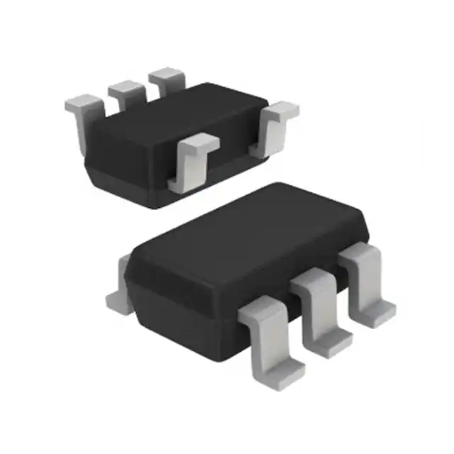
EQ8441 is housed in an SOP package (Small Outline Package), compatible with standard surface-mount assembly processes and optimized for compact optical module integration.
| Pin/Terminal | Circuit Role | Design Meaning |
|---|---|---|
| VDD | Positive supply input | Accepts 2.5–3.3 V DC; powers internal analog/digital circuitry |
| GND | Ground reference | Common return path for supply and signal circuits |
| CLK | External clock input | Enables synchronous sampling; overrides internal oscillator when driven |
| DATA | Serial digital output | Transmits time-multiplexed X/Y coordinate data in LSB-first format |
| INT | Interrupt output | Active-low signal indicating new position data is ready for readout |
| VREF | Reference voltage input | Provides stable bias for internal ADC; typically tied to VDD or decoupled |
Key Features
| Feature | Design Value |
|---|---|
| Integrated 4-Hall-element array | Enables true 2D coordinate detection without external sensor alignment or calibration |
| On-chip 8-bit A/D converter | Converts analog Hall differentials directly to digital X/Y values-no external ADC required |
| Intermittent operation circuit | Reduces average current draw by >90% during idle periods in lens positioning cycles |
| Hardware interrupt output (INT) | Eliminates polling overhead; allows host MCU to enter deep sleep between position updates |
| SOP package with 3.1 mm element pitch | Ensures mechanical stability and thermal matching across all four Hall sensors |
Applications
| Lens Positioning in DSC/DVC Anti-Shake | Autofocus Lens Actuation |
|---|---|
Use Scenario: Compensating for hand tremor in digital still/video cameras by dynamically repositioning image sensor or lens group. IC Role / Device Role / Timing Role: EQ8441 serves as closed-loop position feedback sensor, delivering real-time X/Y displacement data to servo controller. Use Value: Achieves ±1 µm repeatability over 1–5 mm stroke, enabling sub-pixel image stabilization without mechanical backlash. | Use Scenario: Precisely controlling lens element movement during autofocus acquisition in compact camera modules. IC Role / Device Role / Timing Role: EQ8441 provides high-resolution positional feedback to drive coil current in voice-coil motor (VCM) actuators. Use Value: Enables <5 ms response time with <0.5 µm quantization error, supporting fast, silent, and accurate focus lock. |
| Zoom Lens Linear Tracking | Optical Image Stabilization (OIS) Calibration |
Use Scenario: Monitoring axial displacement of zoom lens groups to maintain optical alignment and focal length consistency. IC Role / Device Role / Timing Role: EQ8441 acts as absolute linear position transducer, outputting calibrated X/Y coordinates referenced to lens home position. Use Value: Delivers monotonic, drift-free output across temperature (−30°C to +85°C), eliminating need for periodic recalibration. | Use Scenario: Factory calibration of OIS actuator travel limits and linearity correction coefficients during module assembly. IC Role / Device Role / Timing Role: EQ8441 functions as metrology-grade reference sensor during automated test fixture motion profiling. Use Value: Provides traceable ±2 µm measurement uncertainty at 25°C, meeting ISO/IEC 17025 calibration traceability requirements. |
Equivalent & Alternatives
The following parts are listed as comparable options for similar 2D Hall position sensing applications.
| Alternative Part | Technical Difference | Application Difference | Selection Advice |
|---|---|---|---|
| Allegro A1335 | 32-bit SPI output, higher resolution (12-bit X/Y), wider supply (3–3.6 V), no INT pin | Targets industrial encoders and robotics; lacks built-in interrupt for low-power polling avoidance | Select when higher resolution and SPI compatibility outweigh power-down efficiency and interrupt-driven operation |
| Melexis MLX90393 | Tri-axis magnetic field sensing, I²C/SPI interface, 16-bit XYZ output, 2.2–3.6 V supply | Designed for 3D joystick and rotary encoder use; requires external processing for 2D coordinate derivation | Select when multi-axis flexibility and field-strength telemetry are needed beyond fixed 2D lens tracking |
Compared with EQ8441, A1335 offers greater resolution but removes hardware interrupt capability critical for low-power optical modules, while MLX90393 adds third-axis sensing at the cost of increased firmware complexity and reduced integration density in space-constrained lens barrels.
Availability
EQ8441 is available at Aetrix Electronics and suitable for digital still camera (DSC), digital video camera (DVC), and optical image stabilization (OIS) module design requiring stable component supply, tight position feedback accuracy, and long-term production continuity.
Supply support for EQ8441 includes scheduled delivery planning, volume procurement assistance, BOM continuity management, traceable sourcing, and lifecycle availability coordination for OEM customers, industrial embedded developers, connected-device designers, and electronics production programs.
Manufacturer
Asahi Kasei EMD Corp. is a global leader in Hall-effect sensor technology, headquartered in Tokyo, Japan, with over 1 billion Hall elements shipped annually and deep expertise in magnetic simulation and field measurement.
The EQ8441 belongs to Asahi Kasei's EQ-series Hall IC product line, engineered specifically for high-accuracy, low-power 2D position sensing in compact optical systems such as autofocus and anti-shake mechanisms.
FAQ
What is the operating voltage range for EQ8441?
The EQ8441 operates from 2.5 V to 3.3 V DC. This narrow supply range ensures compatibility with 3.3 V logic domains common in camera module SoCs and minimizes noise coupling into sensitive analog Hall front-ends. Operation outside this range may cause undefined behavior or permanent damage to the internal circuitry of EQ8441.
Does EQ8441 require an external magnet, and what type is recommended?
Yes, EQ8441 requires an external diametrically or radially magnetized neodymium magnet positioned above the package. Asahi Kasei recommends magnets with surface field strength ≥100 mT and consistent pole geometry to ensure linear response across the 1–5 mm stroke range specified for EQ8441. Magnet placement tolerance must be maintained within ±0.3 mm for ±1 µm accuracy.
How does the interrupt (INT) pin function in EQ8441?
The INT pin on EQ8441 asserts a low-level pulse each time new X/Y coordinate data is ready for readout via the DATA pin. This hardware event eliminates software polling, allowing host microcontrollers to remain in deep sleep until position update occurs-critical for extending battery life in portable imaging devices using EQ8441.
Can EQ8441 be used in automotive applications?
No, EQ8441 is rated for −30°C to +85°C operation and lacks AEC-Q200 qualification. It is designed for consumer optical modules-not automotive environments. For under-hood or ADAS applications, Asahi Kasei offers AE-8001 (−40°C to +125°C, 12-bit) as a qualified alternative, not EQ8441.
What is the role of VREF on EQ8441?
VREF on EQ8441 serves as the reference voltage input for the internal 8-bit ADC. It must be connected to a clean, low-noise 3.3 V source or decoupled with a 100 nF capacitor to ground. Incorrect VREF routing introduces gain error and nonlinearity in the X/Y coordinate output of EQ8441, degrading position accuracy beyond ±5 µm.
EQ8441 Specifications
- Product attributes
- Attribute value
- Manufacturer:
- Asahi Kasei Microdevices/AKM
- Series:
- *
- Package/Case:
- -
- Packaging:
- Tape & Reel (TR)
- Product Status:
- Obsolete
- Technology:
- -
- Axis:
- -
- Output Type:
- -
- Sensing Range:
- -
- Voltage - Supply:
- -
- Current - Supply (Max):
- -
- Current - Output (Max):
- -
- Resolution:
- -
- Bandwidth:
- -
- Operating Temperature:
- -
- Grade:
- -
- Qualification:
- -
- Features:
- -
- Supplier Device Package:
- -
- Mounting Type:
- -
EQ8441 FAQ
1.How can I place an order for EQ8441 through Aetrix?
Please submit a Request for Quotation (RFQ) for EQ8441 on Aetrix. Our sales agent will provide a competitive quotation and guide you through the order confirmation once you accept the terms.
2.Are the price and stock information for EQ8441 reliable?
The price and inventory of EQ8441 are updated periodically and may fluctuate due to market conditions. Stock and pricing data are typically refreshed every 24 hours. Quotation validity for EQ8441 is usually 5 days.
3.What payment methods are accepted for EQ8441?
We accept Wire Transfer, PayPal, Credit Card, Western Union, MoneyGram, and Escrow for EQ8441 transactions.
Note: Certain payment methods may incur a processing fee.
4.How is shipping managed for EQ8441?
EQ8441 orders can be shipped via leading logistics carriers, including DHL, UPS, FedEx, TNT, or Registered Mail.
Once your EQ8441 order is processed, you will receive an email with the shipment details and tracking number.
Note: Tracking information may take up to 24 hours to appear. Express delivery typically takes 3–5 business days.
5.How can I obtain technical support or documentation for EQ8441?
For technical support, including EQ8441 datasheets, pinout diagrams, or application guidance, please contact our engineering support team. They can provide detailed documentation and assistance for your EQ8441 requirements.
6.How does Aetrix verify that EQ8441 is sourced from the original manufacturer or authorized distributors?
All EQ8441 products on Aetrix are procured from qualified distributors and authorized channels. Our dedicated quality assurance team conducts strict verification, including traceability checks and, if necessary, third-party testing. This ensures that EQ8441 meets industry standards.
7.What is the process for return or replacement of EQ8441?
All EQ8441 units undergo pre-shipment inspection (PSI). If there is an issue with EQ8441, returns or replacements are accepted under the following conditions:
1.Quantity discrepancies, incorrect items, or visible external defects (such as breakage or corrosion), acknowledged by Aetrix.
2.The issue is reported within 90 days of delivery.
3.The EQ8441 part is unused and in its original packaging.
Return procedure for EQ8441:
1.Submit a request within 90 days.
2.Obtain a Return Material Authorization (RMA) from Aetrix.
EQ8441 Tags
-
DRV5053VAQDBZR
Texas Instruments
-
MMC5603NJ
Memsic Inc.

-
DRV5055A1QDBZR
Texas Instruments
-
MLX90392ELQ-AAA-011-RE
Melexis Technologies NV

-
CT100LW-HS6
Allegro MicroSystems
-
DRV5056A1ELPGMQ1
Texas Instruments
-
A1304ELHLX-T
Allegro MicroSystems
-
MMC5633NJL
Memsic Inc.
-
A1308KUA-2-T
Allegro MicroSystems
-
A1308KUA-1-T
Allegro MicroSystems
-
SI7210-B-04-IVR
Silicon Labs
-
A1308LLHLT-2-T
Allegro MicroSystems
Tech Hub

A practical engineering and sourcing framework covering lifecycle verification, lifetime-buy calculations, replacement qualification, supplier checks and counterfeit-risk controls.

TTL and CMOS logic families differ in thresholds, loading, output drive, power and timing. This engineering guide compares 74HC and 74HCT, calculates noise margins and checks 3.3 V/5 V compatibility.

A practical engineering guide to 3.3V and 5V logic compatibility, input thresholds, resistor dividers, translator ICs, MOSFET level shifting, I2C pull-ups, timing limits and power-sequencing risks.

The 74HC595 uses push-pull logic outputs, while the TPIC6B595 uses 50 V open-drain DMOS sinks for higher-power loads. This guide compares timing, current limits, 3.3 V interfacing, load wiring, thermal…

The 74HC595 converts serial data into eight stable parallel outputs. This guide covers pin functions, shift and storage timing, OE and MR behavior, drive-current limits, cascading, voltage compatibilit…

A technical comparison of level-sensitive latches and edge-triggered flip-flops, covering timing windows, setup and hold limits, master–slave operation, time borrowing, race-through, HDL inference and…

A D latch stores one bit while Enable controls when data can pass. This reference covers gate-level operation, truth tables, transparency, setup and hold timing, LE versus OE, common ICs and practical …

An SR latch stores one bit through cross-coupled feedback. This engineering reference covers NOR and NAND implementations, truth tables, forbidden-state recovery, gated operation, switch debouncing, fa…

Latch circuits retain one bit through feedback. This technical reference covers SR and D latches, truth tables, transparency, timing limits, latch-versus-flip-flop behavior, applications and common log…

An engineering guide to LED driver operation, constant-current and constant-voltage outputs, linear and switching topologies, dimming, IC selection, calculations, replacement compatibility, and fault c…


