
 My Inquiry
 My Account


Microchip Technology EQCO850SC.3
- Part No.:
- EQCO850SC.3
- Manufacturer:
- Microchip Technology
- Category:
- Specialized
- Package:
- 16-VQFN Exposed Pad
- Datasheet:
-
 EQCO850SC.3.pdf
- Description:
- IC INTERFACE SPECIALIZED 16QFN
- Quantity:
- Payment:

- Shipping:

Inventory:1,650
Please send an inquiry. Send us your inquiry, and we will respond immediately.
Product details
Overview
EQCO850SC.3 from Microchip Technology is a single-coax full-duplex transceiver IC designed for Fast Ethernet (125 Mbps) over 50Ω coaxial cable, integrating transmitter, receiver, and adaptive equalizer functions. It supports PoE-based power and data distribution, features integrated 50Ω termination, operates from a single 3.3V supply, and delivers 205 mW typical power consumption. It is used in IP camera links, industrial inspection systems, and coax-based home networking where Cat5/Cat6 cabling is unavailable.
For engineers reviewing the EQCO850SC.3 datasheet, EQCO850SC.3 pinout, EQCO850SC.3 application, or EQCO850SC.3 equivalent, this page provides verified technical context, package mapping, real-world range performance (40–70 m on RG174/RTK/RG58), functional pin roles, and validated alternative options for 50Ω coax Ethernet extension designs.
Technical Context
The EQCO850SC.3 implements a hybrid active splitter/combiner architecture that enables simultaneous bidirectional transmission and reception on a single 50Ω coax cable. Its embedded equalizer core performs auto-adaptive compensation for cable attenuation up to 10 dB at 62.5 MHz, with convergence in microseconds upon signal detection.
It accepts LVDS-like differential inputs (SDIp/SDIn) terminated on-chip at 104 Ω nominal, drives LVDS-like differential outputs (SDOp/SDOn) with 350 mV typical amplitude and 240 ps typical rise time, and uses SDIO/REF as a balanced coax interface with 51 Ω nominal input impedance referenced to AGND.
Key Specifications
| Parameter | Value and Actual Design Meaning |
|---|---|
| Data Rate | 125 Mbps - matches IEEE 802.3 FX Fast Ethernet physical layer timing. |
| Cable Impedance | 50Ω - requires precise 50Ω coax (RG174, RTK, RG58) and matching PCB trace routing. |
| Supply Voltage | 3.3 V ±3% - single-rail operation with DVCC and AVCC pins separated for noise isolation. |
| Power Consumption | 205 mW typical - enables thermal management in compact enclosures without forced cooling. |
| Operating Temp | −10°C to +70°C - qualified for industrial ambient environments including surveillance enclosures. |
| Max Cable Range | 70 m - achievable on RG58 or RTK coax per Table 2, limited by frequency-dependent attenuation. |
| Equalizer Bandwidth | Up to 62.5 MHz - adapts to cable loss profile to restore 4B/5B encoded signal integrity. |
Pinout & Package
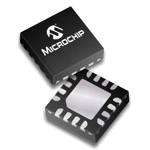
EQCO850SC.3 is housed in a 16-pin, 4 mm × 4 mm × 0.9 mm QFN package with 0.65 mm pitch and exposed thermal pad. The package is Pb-free and RoHS compliant, with pin 1 marked by a hatched corner indicator.
| Pin/Terminal | Circuit Role | Design Meaning |
|---|---|---|
| GND (Pin 1) | Power ground reference | Common return for digital circuitry; must connect to system ground plane. |
| DVCC (Pin 15) | Digital supply voltage | +3.3V supply for digital logic and control circuitry; decouple locally with 100 nF capacitor. |
| DGND (Pin 13) | Digital ground | Reference for SDIp/SDIn and SDOp/SDOn differential pairs; tie directly to DVCC ground. |
| AVCC (Pin 1) | Analog supply voltage | +3.3V analog rail filtered via ferrite bead and capacitor to reduce noise coupling into coax interface. |
| AGND (Pin 3) | Analog ground | Direct connection point to coax cable outer screen; critical for EMI suppression and return-loss control. |
| SDIO (Pin 2) | Coax bidirectional I/O | Single-ended interface to center conductor of 50Ω coax; carries combined TX+RX signal. |
| REF (Pin 4) | Coax reference current | Anti-phase current path to SDIO; must terminate to AGND via 50Ω resistor matched to cable Z₀. |
| SDIp / SDIn (Pins 10, 9) | Differential RX input | LVDS-like input pair from PHY FX Out; internally terminated at 104 Ω differential. |
| SDOp / SDOn (Pins 12, 11) | Differential TX output | LVDS-like output pair to PHY FX In; 350 mV typical amplitude, 100Ω differential output impedance. |
| OPT0 / OPT1 (Pins 14, 5) | Mode configuration | Fast Ethernet mode enabled when OPT0 = DGND and OPT1 = DVCC; hardwired during design. |
Key Features
| Feature | Design Value |
|---|---|
| Integrated 50Ω coax termination | Eliminates external resistors, reduces BOM count and layout sensitivity for 50Ω systems. |
| Auto-adaptive equalizer core | Compensates for up to 10 dB cable loss at 62.5 MHz without manual tuning or firmware. |
| PoE-over-coax support | Enables simultaneous 48 V DC power and 125 Mbps data delivery over same coax cable. |
| LVDS-compatible I/O interfaces | Direct connection to standard FX-compliant PHYs without level-shifting or AC-coupling redesign. |
| Low-power 3.3V operation | 205 mW total dissipation allows use in thermally constrained housings like outdoor camera enclosures. |
Applications
| IP Camera Backhaul | Industrial Coax Networking |
|---|---|
Use Scenario: Extending 125 Mbps Fast Ethernet from NVR to remote PTZ or thermal cameras over existing RG58 coax in factory floors. IC Role / Device Role / Timing Role: Full-duplex transceiver enabling simultaneous video streaming and PTZ control signaling over single coax. Use Value: Avoids rewiring with Cat6; achieves 70 m reach on RG58 while maintaining IEEE 802.3 FX compliance and PoE power delivery. |
Use Scenario: Connecting machine vision controllers to inspection cameras in metal-rich environments where UTP EMI immunity is insufficient. IC Role / Device Role / Timing Role: Coax PMD layer translating FX PHY signals into robust 50Ω baseband transmission. Use Value: Provides 10 dB adaptive equalization to counteract high-frequency loss in long RG174 runs inside machinery. |
| Home Coax Infrastructure Reuse | STB-to-TV Inter-Room Link |
Use Scenario: Repurposing unused 50Ω coax drops in apartments for Ethernet backhaul between Wi-Fi mesh nodes. IC Role / Device Role / Timing Role: Bidirectional media converter bridging Ethernet MAC layer to coax physical medium. Use Value: Delivers deterministic 125 Mbps throughput without RF interference from adjacent TV spectrum, unlike MoCA. |
Use Scenario: Transmitting uncompressed HD video metadata and control commands between set-top box and display over short coax runs. IC Role / Device Role / Timing Role: Low-jitter (40% UI peak-to-peak) transceiver preserving signal integrity for real-time control paths. Use Value: Enables plug-and-play interconnect without HDMI cable limitations or latency-sensitive retransmission protocols. |
Equivalent & Alternatives
The following parts are listed as comparable options for similar coaxial Fast Ethernet transceiver applications.
| Alternative Part | Technical Difference | Application Difference | Selection Advice |
|---|---|---|---|
| EQCO875SC.3 | Optimized for 75Ω coax (RG6/RG11); 225 m max range; identical pinout and register map. | Used in broadcast-grade coax infrastructure (e.g., CATV headend links), not 50Ω RF test or industrial cabling. | Select only if deploying on 75Ω infrastructure; not a drop-in replacement for EQCO850SC.3 in 50Ω systems due to impedance mismatch. |
| MAX24287 | Single-ended coax interface; no integrated equalizer; requires external equalization or limits range to ≤30 m on RG58. | Targeted at cost-sensitive analog video + data overlay, not standards-compliant Fast Ethernet. | Choose when PoE and IEEE 802.3 FX compliance are not required; EQCO850SC.3 provides superior jitter and range without external components. |
Compared with EQCO875SC.3 and MAX24287, the EQCO850SC.3 uniquely delivers adaptive equalization, integrated 50Ω termination, and full Fast Ethernet compliance in one QFN package-enabling 70 m operation on common industrial coax without layout-compromising external circuits.
Availability
EQCO850SC.3 is available at Aetrix Electronics and suitable for IP camera backhaul, industrial machine vision networking, and coax-based home Ethernet extension requiring stable component supply across production lifecycles.
Supply support for EQCO850SC.3 includes scheduled delivery planning, volume procurement assistance, BOM continuity management, traceable sourcing, and lifecycle availability coordination for OEM customers, industrial embedded developers, connected-device designers, and electronics production programs.
Manufacturer
Microchip Technology is a global semiconductor company specializing in microcontrollers, analog devices, and connectivity solutions, with ISO/TS-16949 certified manufacturing and design facilities.
The EQCO850SC.3 belongs to Microchip's Ethernet-over-Coax transceiver product line, engineered specifically to extend Fast Ethernet over legacy 50Ω coax infrastructure while maintaining IEEE 802.3 FX compliance and PoE capability.
FAQ
What is the maximum supported cable length for EQCO850SC.3?
The EQCO850SC.3 achieves up to 70 meters on RG58 or RTK coaxial cables, as confirmed in Table 2 of the DS60001314A datasheet. Performance depends on cable quality and frequency-dependent attenuation; RG174 yields 40 m. The adaptive equalizer compensates for up to 10 dB loss at 62.5 MHz, enabling reliable 125 Mbps operation within these ranges. EQCO850SC.3 does not support longer distances without repeaters or signal regeneration.
Does EQCO850SC.3 require external termination resistors?
No, EQCO850SC.3 integrates on-die 50Ω termination for the coax interface (SDIO/REF), eliminating the need for external resistors in standard configurations. External 50Ω matching is still required on the PCB trace between the device and coax connector, and the REF pin must connect to AGND through a precision 50Ω resistor. This integration reduces BOM count and improves impedance control versus discrete solutions.
Can EQCO850SC.3 be used with standard Fast Ethernet PHYs?
Yes, EQCO850SC.3 is fully compatible with IEEE 802.3 FX-compliant PHYs. Its SDIp/SDIn inputs accept LVDS-like differential signals with 104 Ω on-chip termination, and its SDOp/SDOn outputs deliver LVDS-like 350 mV differential signals into 100Ω loads. No level-shifting or protocol translation is needed - EQCO850SC.3 operates transparently in the PMD layer between PHY and coax medium.
Is EQCO850SC.3 pin-compatible with EQCO875SC.3?
Yes, EQCO850SC.3 and EQCO875SC.3 share identical pinout, package dimensions, and electrical interface definitions. However, they are impedance-optimized for different coax types: EQCO850SC.3 for 50Ω systems (RG58/RTK), EQCO875SC.3 for 75Ω (RG6/RG11). Swapping them without adjusting termination and layout will degrade return loss and range performance.
What power supply requirements does EQCO850SC.3 have?
EQCO850SC.3 requires a single 3.3 V supply with ±3% tolerance (3.2–3.4 V), delivering 62.5 mA typical supply current under full transmit/receive operation. AVCC and DVCC must be separately decoupled: AVCC via ferrite bead + capacitor to coax shield, DVCC with 100 nF capacitor near Pin 15. Failure to isolate analog and digital supplies increases jitter and degrades equalizer convergence.
EQCO850SC.3 Specifications
- Product attributes
- Attribute value
- Manufacturer:
- Microchip Technology
- Series:
- -
- Package/Case:
- 16-VQFN Exposed Pad
- Packaging:
- Tube
- Product Status:
- Active
- Applications:
- Camera
- Interface:
- -
- Voltage - Supply:
- 3.3V
- Supplier Device Package:
- 16-QFN (4x4)
- Grade:
- -
- Qualification:
- -
- Mounting Type:
- Surface Mount
EQCO850SC.3 FAQ
1.How can I place an order for EQCO850SC.3 through Aetrix?
Please submit a Request for Quotation (RFQ) for EQCO850SC.3 on Aetrix. Our sales agent will provide a competitive quotation and guide you through the order confirmation once you accept the terms.
2.Are the price and stock information for EQCO850SC.3 reliable?
The price and inventory of EQCO850SC.3 are updated periodically and may fluctuate due to market conditions. Stock and pricing data are typically refreshed every 24 hours. Quotation validity for EQCO850SC.3 is usually 5 days.
3.What payment methods are accepted for EQCO850SC.3?
We accept Wire Transfer, PayPal, Credit Card, Western Union, MoneyGram, and Escrow for EQCO850SC.3 transactions.
Note: Certain payment methods may incur a processing fee.
4.How is shipping managed for EQCO850SC.3?
EQCO850SC.3 orders can be shipped via leading logistics carriers, including DHL, UPS, FedEx, TNT, or Registered Mail.
Once your EQCO850SC.3 order is processed, you will receive an email with the shipment details and tracking number.
Note: Tracking information may take up to 24 hours to appear. Express delivery typically takes 3–5 business days.
5.How can I obtain technical support or documentation for EQCO850SC.3?
For technical support, including EQCO850SC.3 datasheets, pinout diagrams, or application guidance, please contact our engineering support team. They can provide detailed documentation and assistance for your EQCO850SC.3 requirements.
6.How does Aetrix verify that EQCO850SC.3 is sourced from the original manufacturer or authorized distributors?
All EQCO850SC.3 products on Aetrix are procured from qualified distributors and authorized channels. Our dedicated quality assurance team conducts strict verification, including traceability checks and, if necessary, third-party testing. This ensures that EQCO850SC.3 meets industry standards.
7.What is the process for return or replacement of EQCO850SC.3?
All EQCO850SC.3 units undergo pre-shipment inspection (PSI). If there is an issue with EQCO850SC.3, returns or replacements are accepted under the following conditions:
1.Quantity discrepancies, incorrect items, or visible external defects (such as breakage or corrosion), acknowledged by Aetrix.
2.The issue is reported within 90 days of delivery.
3.The EQCO850SC.3 part is unused and in its original packaging.
Return procedure for EQCO850SC.3:
1.Submit a request within 90 days.
2.Obtain a Return Material Authorization (RMA) from Aetrix.
EQCO850SC.3 Tags

-
NVT4857UKAZ
NXP Semiconductors

-
TCA8418RTWR
Texas Instruments

-
PCA9546APWR
Texas Instruments

-
MD0100N8-G
Microchip Technology

-
PCA9548APW,118
NXP Semiconductors

-
PCA9540BDP,118
NXP Semiconductors

-
PCA9548APWR
Texas Instruments

-
PCA9546APW,118
NXP Semiconductors

-
PTN3360DBS,518
NXP Semiconductors

-
PCA9546ABS,118
NXP Semiconductors

-
PCA9518PWR
Texas Instruments

-
PCA9545APW,118
NXP Semiconductors
Tech Hub

TTL and CMOS logic families differ in thresholds, loading, output drive, power and timing. This engineering guide compares 74HC and 74HCT, calculates noise margins and checks 3.3 V/5 V compatibility.

A practical engineering guide to 3.3V and 5V logic compatibility, input thresholds, resistor dividers, translator ICs, MOSFET level shifting, I2C pull-ups, timing limits and power-sequencing risks.

The 74HC595 uses push-pull logic outputs, while the TPIC6B595 uses 50 V open-drain DMOS sinks for higher-power loads. This guide compares timing, current limits, 3.3 V interfacing, load wiring, thermal…

The 74HC595 converts serial data into eight stable parallel outputs. This guide covers pin functions, shift and storage timing, OE and MR behavior, drive-current limits, cascading, voltage compatibilit…

A technical comparison of level-sensitive latches and edge-triggered flip-flops, covering timing windows, setup and hold limits, master–slave operation, time borrowing, race-through, HDL inference and…

A D latch stores one bit while Enable controls when data can pass. This reference covers gate-level operation, truth tables, transparency, setup and hold timing, LE versus OE, common ICs and practical …

An SR latch stores one bit through cross-coupled feedback. This engineering reference covers NOR and NAND implementations, truth tables, forbidden-state recovery, gated operation, switch debouncing, fa…

Latch circuits retain one bit through feedback. This technical reference covers SR and D latches, truth tables, transparency, timing limits, latch-versus-flip-flop behavior, applications and common log…

An engineering guide to LED driver operation, constant-current and constant-voltage outputs, linear and switching topologies, dimming, IC selection, calculations, replacement compatibility, and fault c…

Operational amplifier guide covering op amp basics, feedback, ideal vs real op amps, common configurations, buffer circuits, offset, bias current, gain-bandwidth, slew rate, rail-to-rail limits and sel…


