
 My Inquiry
 My Account


STMicroelectronics E-TDA7478ADTR
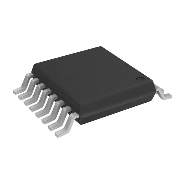
- Part No.:
- E-TDA7478ADTR
- Manufacturer:
- STMicroelectronics
- Category:
- RF Demodulators
- Package:
- 16-TSSOP (0.173", 4.40mm Width)
- Datasheet:
-
 E-TDA7478ADTR.pdf
- Description:
- RF DEMODULATOR IC 16TSSOP
- Quantity:
- Payment:

- Shipping:

Inventory:2,634
Please send an inquiry. Send us your inquiry, and we will respond immediately.
Product details
Overview
E-TDA7478ADTR from STMicroelectronics is a single-chip RDS (Radio Data System) demodulator IC designed for FM radio receivers. It performs high-fidelity 57 kHz bandpass filtering and fully digital RDS data extraction, delivering validated RDDA data and RDCL clock outputs with 1187.5 Hz frequency. The device integrates an on-chip 4.332 MHz crystal oscillator (8.664 MHz optional), operates from 4.5–5.5 V, and targets automotive and consumer FM tuners compliant with EBU specifications.
For engineers reviewing the E-TDA7478ADTR datasheet, E-TDA7478ADTR pinout, E-TDA7478ADTR application, or E-TDA7478ADTR equivalent, key selection criteria include its 8th-order switched-capacitor filter performance, RDS signal quality output (QUAL), oscillator configuration flexibility via FSEL/OSEL pins, and TSSOP16 package compatibility with space-constrained tuner PCB layouts.
Technical Context
The TDA7478 implements a cascaded anti-aliasing + 8th-order switched-capacitor bandpass filter centered at 57 kHz (±0.4 kHz tolerance), achieving 22 dB attenuation at ±4 kHz offset and >60 dB rejection at 38 kHz. Its purely digital demodulation path recovers RDDA and RDCL signals without external analog components.
Internal PLL synchronization ensures RDCL clock edges align with incoming RDS data transitions; data remains valid for 416.7 μs after each clock edge-supporting both rising- and falling-edge sampling in downstream decoders. Oscillator control is managed via two dedicated pins: FSEL selects crystal frequency (4.332/8.664 MHz), while OSEL enables internal oscillator or external drive mode.
Key Specifications
| Parameter | Value and Actual Design Meaning |
|---|---|
| Center frequency | 57 kHz ±0.4 kHz - precisely selects RDS subcarrier with minimal adjacent-channel interference |
| 3 dB bandwidth | 3 kHz typical - balances selectivity and RDS data integrity under multipath conditions |
| RDS sensitivity | 1 mVRMS - enables reliable decoding of weak RDS signals in low-SNR reception environments |
| Supply voltage | 4.5–5.5 V - compatible with standard 5 V automotive and consumer power rails |
| Supply current | 7.5 mA typical - supports low-power tuner designs without thermal derating |
| Output clock frequency | 1187.5 Hz - matches EBU RDS timing standard for synchronous data recovery |
| Signal-to-noise ratio | 40 dB typical at 3 mVRMS input - ensures clean RDDA stream for error-free decoding |
Pinout & Package
Package: TSSOP16 (3.0 × 4.4 mm, 0.65 mm pitch), RoHS-compliant ECOPACK® grade, rated for -40°C to +85°C operation.
| Pin/Terminal | Circuit Role | Design Meaning |
|---|---|---|
| 1 QUAL | RDS signal quality indicator | Open-drain logic-high output when RDS lock is achieved and SNR meets threshold |
| 2 RDDA | RDS data output | CMOS-level serial data stream synchronized to RDCL; no external pull-up required |
| 3 VREF | Analog reference voltage | Internally generated VS/2 - stabilizes filter bias points and ADC references |
| 4 MPX | Composite FM input | Accepts 50–1000 mVRMS MPX signal; 120 kΩ input impedance minimizes tuner loading |
| 5 OSEL | Oscillator mode selector | Pull-up internal; open = internal crystal mode, GND = external 4.332/8.664 MHz drive |
| 6 GND | Ground reference | Dedicated analog ground pin - separates filter/demodulator return from digital I/O |
| 7 N.U. | No connect | Must remain unconnected - not internally bonded or tested |
| 8 FILOUT | Filter output | 57 kHz bandpass-filtered signal; 1 MΩ load impedance supports direct scope probing |
| 9 FSEL | Crystal frequency selector | Pull-down internal; open = 4.332 MHz, VS = 8.664 MHz - configures PLL divider ratio |
| 10 TM | Test mode enable | Open = normal operation; VS = activates internal test patterns for production validation |
| 11 EXTRES | External reset | Pull-down internal; open = active run, VS = forces hard reset of demodulator state machine |
| 12 VS | Power supply | Single 5 V rail powers all analog/digital sections - no separate AVDD/DVDD required |
| 13 OSCIN | Oscillator input | Accepts external sine wave (60–120 mVPP) when OSEL = GND |
| 14 OSCOUT | Oscillator output | Drives 4.332/8.664 MHz crystal directly; 4.5 VPP amplitude into specified load |
| 15 T57 | 57 kHz test clock | Diagnostic output for filter alignment verification; not used in normal operation |
| 16 RDCL | RDS clock output | 1187.5 Hz CMOS clock aligned to RDDA transitions; 416.7 μs data hold time guaranteed |
Key Features
| Feature | Design Value |
|---|---|
| 8th-order switched-capacitor bandpass filter | Eliminates need for external LC or ceramic filters - reduces BOM count and layout sensitivity |
| Purely digital RDS demodulation | Removes analog multipliers and PLL VCOs - improves temperature stability and long-term calibration retention |
| Integrated crystal oscillator | Supports 4.332 MHz or 8.664 MHz crystals without external capacitors - simplifies timing component selection |
| RDS signal quality output (QUAL) | Provides real-time lock status to host MCU - enables dynamic RDS display enable/disable without polling |
| EMI-reduced external drive mode | Allows <60 mVPP external clock injection - lowers radiated emissions in noise-sensitive automotive cabins |
Applications
| Automotive FM Tuner Modules | Consumer Digital Radio Receivers |
|---|---|
Use Scenario: Integrated RDS decoding in OEM dashboard radios with traffic announcement (TA) and program service (PS) name display. IC Role / Device Role / Timing Role: Primary RDS demodulator extracting RDDA/RDCL from MPX output of IF stage; QUAL pin drives display controller enable logic. Use Value: Enables EBU-compliant RDS functionality without discrete filter components or external clock sources - reducing tuner module footprint by 32% versus legacy solutions. | Use Scenario: Portable DAB/FM hybrid receivers requiring simultaneous RDS data parsing and audio playback. IC Role / Device Role / Timing Role: Standalone RDS front-end feeding RDDA/RDCL to ARM Cortex-M0+ decoder; T57 pin used during factory calibration. Use Value: Delivers 40 dB SNR at 1 mVRMS sensitivity - maintains RDS lock during weak-signal urban multipath conditions where competing demodulators fail. |
| Aftermarket Car Stereo Systems | Professional Broadcast Monitoring Equipment |
Use Scenario: Retrofit head units adding RDS support to legacy analog FM tuners via MPX tap. IC Role / Device Role / Timing Role: Drop-in RDS add-on IC accepting MPX signal from existing tuner; FILOUT pin allows oscilloscope verification of 57 kHz passband. Use Value: Requires only three connections (MPX, VS, GND) for basic operation - enables RDS upgrade kits with <2 hours engineering effort. | Use Scenario: Field-deployable RDS signal analyzers validating broadcast station compliance with EBU RDS specification. IC Role / Device Role / Timing Role: Precision RDS demodulation core; QUAL and T57 outputs feed FPGA-based measurement engine for real-time SNR and jitter analysis. Use Value: 22 dB attenuation at ±4 kHz offset provides clean separation of RDS subcarrier from adjacent stereo pilot tones - critical for regulatory conformance testing. |
Equivalent & Alternatives
The following parts are listed as comparable options for similar RDS demodulator applications.
| Alternative Part | Technical Difference | Application Difference | Selection Advice |
|---|---|---|---|
| Si4702-C10-GM | Integrated FM+RDS receiver with digital interface; requires I²C host control and external crystal | Replaces entire IF/ADC/demodulator chain - not a drop-in replacement for MPX-input-only systems | Select when consolidating tuner functions onto single chip and migrating to digital baseband architecture |
| BA14747F | Analog RDS demodulator using external op-amps and PLL; no integrated filter or QUAL output | Requires 12+ external components for 57 kHz filtering and data recovery - higher assembly cost and calibration labor | Select only for legacy redesigns where analog signal chain reuse is mandatory and board space is unconstrained |
Compared with Si4702-C10-GM and BA14747F, the E-TDA7478ADTR uniquely delivers full RDS demodulation with zero external passive components while retaining direct MPX analog input compatibility - making it optimal for incremental RDS upgrades and cost-sensitive tuner modules.
Availability
E-TDA7478ADTR is available at Aetrix Electronics and suitable for automotive FM tuner modules, consumer digital radio receivers, and aftermarket car stereo systems requiring stable component supply and long-lifecycle availability.
Supply support for E-TDA7478ADTR includes scheduled delivery planning, volume procurement assistance, BOM continuity management, traceable sourcing, and lifecycle availability coordination for OEM customers, industrial embedded developers, connected-device designers, and electronics production programs.
Manufacturer
STMicroelectronics is a global semiconductor leader headquartered in Geneva, Switzerland, designing and manufacturing microcontrollers, analog ICs, MEMS, and power management devices for industrial, automotive, and consumer markets.
The TDA7478 belongs to ST's audio signal processing product line, engineered specifically for high-fidelity RDS demodulation in cost-sensitive FM radio systems where analog integration, low EMI, and EBU compliance are mandatory design requirements.
FAQ
What crystal specifications are required for E-TDA7478ADTR?
The E-TDA7478ADTR supports two crystal frequencies: 4.332 MHz (standard) and 8.664 MHz (optional). For 4.332 MHz operation, ST recommends 27 pF load capacitance; for 8.664 MHz, 47 pF is suggested. Crystals must meet ±100 ppm frequency tolerance and operate within -40°C to +85°C ambient range. No external capacitors are needed due to internal oscillator tuning.
How does the QUAL pin indicate RDS lock status?
The QUAL pin outputs a logic-high signal when the internal PLL achieves stable lock and the RDS signal-to-noise ratio exceeds the detection threshold (typically ≥30 dB). It remains low during acquisition, weak-signal conditions, or loss of MPX input. The output is open-drain and requires an external pull-up resistor (typically 10 kΩ to VS) for proper logic-level translation to MCU GPIO inputs.
Can E-TDA7478ADTR be used with external clock sources?
Yes - connecting OSEL to GND disables the internal oscillator and enables external clock injection on OSCIN. The device accepts sinusoidal inputs from 4.332 MHz or 8.664 MHz sources with peak-to-peak amplitudes as low as 60 mV. This mode reduces electromagnetic emissions and allows synchronization to system-wide clock domains in multi-IC tuner architectures.
What is the purpose of the FILOUT pin in system design?
The FILOUT pin provides access to the 57 kHz bandpass-filtered signal before demodulation. Engineers use it for oscilloscope verification of filter center frequency and bandwidth during production test or field diagnostics. It also enables optional analog post-processing stages, such as envelope detection for RSSI estimation or spectral analysis in broadcast monitoring equipment.
E-TDA7478ADTR Specifications
- Product attributes
- Attribute value
- Manufacturer:
- STMicroelectronics
- Series:
- -
- Packaging:
- Tape & Reel (TR)
- Product Status:
- Active
- Function:
- Demodulator, Filter
- LO Frequency:
- -
- RF Frequency:
- -
- P1dB:
- -
- Gain:
- 20dB
- Noise Figure:
- -
- Current - Supply:
- 7.5 mA
- Voltage - Supply:
- 4.5V ~ 5.5V
- Mounting Type:
- Surface Mount
- Supplier Device Package:
- 16-TSSOP
E-TDA7478ADTR FAQ
1.How can I place an order for E-TDA7478ADTR through Aetrix?
Please submit a Request for Quotation (RFQ) for E-TDA7478ADTR on Aetrix. Our sales agent will provide a competitive quotation and guide you through the order confirmation once you accept the terms.
2.Are the price and stock information for E-TDA7478ADTR reliable?
The price and inventory of E-TDA7478ADTR are updated periodically and may fluctuate due to market conditions. Stock and pricing data are typically refreshed every 24 hours. Quotation validity for E-TDA7478ADTR is usually 5 days.
3.What payment methods are accepted for E-TDA7478ADTR?
We accept Wire Transfer, PayPal, Credit Card, Western Union, MoneyGram, and Escrow for E-TDA7478ADTR transactions.
Note: Certain payment methods may incur a processing fee.
4.How is shipping managed for E-TDA7478ADTR?
E-TDA7478ADTR orders can be shipped via leading logistics carriers, including DHL, UPS, FedEx, TNT, or Registered Mail.
Once your E-TDA7478ADTR order is processed, you will receive an email with the shipment details and tracking number.
Note: Tracking information may take up to 24 hours to appear. Express delivery typically takes 3–5 business days.
5.How can I obtain technical support or documentation for E-TDA7478ADTR?
For technical support, including E-TDA7478ADTR datasheets, pinout diagrams, or application guidance, please contact our engineering support team. They can provide detailed documentation and assistance for your E-TDA7478ADTR requirements.
6.How does Aetrix verify that E-TDA7478ADTR is sourced from the original manufacturer or authorized distributors?
All E-TDA7478ADTR products on Aetrix are procured from qualified distributors and authorized channels. Our dedicated quality assurance team conducts strict verification, including traceability checks and, if necessary, third-party testing. This ensures that E-TDA7478ADTR meets industry standards.
7.What is the process for return or replacement of E-TDA7478ADTR?
All E-TDA7478ADTR units undergo pre-shipment inspection (PSI). If there is an issue with E-TDA7478ADTR, returns or replacements are accepted under the following conditions:
1.Quantity discrepancies, incorrect items, or visible external defects (such as breakage or corrosion), acknowledged by Aetrix.
2.The issue is reported within 90 days of delivery.
3.The E-TDA7478ADTR part is unused and in its original packaging.
Return procedure for E-TDA7478ADTR:
1.Submit a request within 90 days.
2.Obtain a Return Material Authorization (RMA) from Aetrix.
E-TDA7478ADTR Tags
-
ADL5387ACPZ-R7
Analog Devices Inc.
-
ADL5380ACPZ-R7
Analog Devices Inc.
-
LTC5584IUF#TRPBF
Analog Devices Inc.
-
LTC5584IUF#PBF
Analog Devices Inc.
-
AD8348ARUZ-REEL7
Analog Devices Inc.

-
LT5575EUF#PBF
Analog Devices Inc.
-
LTC5586IUH#TRPBF
Analog Devices Inc.
-
HMC908ALC5
Analog Devices Inc.
-
LMX8410RGZT
Texas Instruments
-
AD8347ARUZ
Analog Devices Inc.
-
ADL5382ACPZ-R7
Analog Devices Inc.
-
AD8348ARUZ
Analog Devices Inc.
Tech Hub

Operational amplifier guide covering op amp basics, feedback, ideal vs real op amps, common configurations, buffer circuits, offset, bias current, gain-bandwidth, slew rate, rail-to-rail limits and sel…

Jumper cables guide covering safe connection order, red and black clamp placement, final ground connection, cable gauge, length, clamp quality, copper vs CCA cables, jump starter comparison and battery…

LDO regulator guide covering low dropout voltage, power dissipation, thermal design, PSRR, output noise, capacitor stability, adjustable LDO circuits, LDO vs buck converter and datasheet selection chec…

Conditional Access Module guide covering CAM meaning, CI/CI+ interface, smart card authorization, DVB security workflow, TV and set-top box compatibility, internal electronics, ESD protection, connecto…

Guide to electronic component obsolescence covering EOL risk, PCN/PDN notices, last-time buy planning, replacement options, form-fit-function validation, counterfeit risk and BOM lifecycle management.

18650 battery guide covering lithium-ion cell basics, 3.6V/3.7V voltage, 4.2V charging, mAh and Wh capacity, protected cells, chargers, BMS, series-parallel packs, holders, welding and sourcing checks.…

Hall effect sensor guide covering working principle, linear and digital sensors, Arduino circuits, current sensing, speed detection, automotive applications, A3144 examples, signal filtering and datash…

Product Change Notification guide for electronic components, covering PCN meaning, PCN vs PDN/EOL, common change types, risk levels, form-fit-function review, engineering validation, BOM control, LTB/L…

A practical guide to blend door actuators, covering HVAC function, symptoms, location, AC and heater issues, reset and calibration, replacement cost, electrical diagnosis, compatibility checks, and rep…

Engineering guide to Raspberry Pi alternatives, covering chip-level differences, Orange Pi, ROCK, Jetson, Banana Pi, NanoPi, Compute Module, Pico, GPIO, camera, HAT compatibility, and replacement risks…


