
 My Inquiry
 My Account


STMicroelectronics E-TDA7478DTR
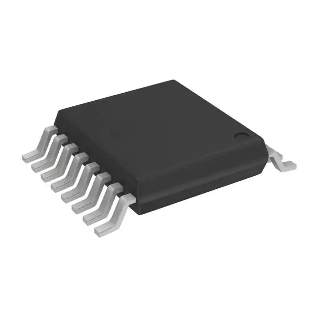
- Part No.:
- E-TDA7478DTR
- Manufacturer:
- STMicroelectronics
- Category:
- RF Demodulators
- Package:
- 16-TSSOP (0.173", 4.40mm Width)
- Datasheet:
-
 E-TDA7478DTR.pdf
- Description:
- RF DEMODULATOR IC 16TSSOP
- Quantity:
- Payment:

- Shipping:

Inventory:4,424
Please send an inquiry. Send us your inquiry, and we will respond immediately.
Product details
Overview
E-TDA7478DTR from STMicroelectronics is a single-chip RDS (Radio Data System) demodulator IC designed for FM radio receivers. It integrates an 8th-order switched-capacitor bandpass filter centered at 57 kHz, fully digital RDS demodulation, and a 4.332 MHz crystal oscillator - all without external passive components. It outputs synchronized RDS data (RDDA), clock (RDCL), and signal quality (QUAL) for EBU-compliant broadcast reception in automotive and consumer audio systems.
For engineers reviewing the E-TDA7478DTR datasheet, E-TDA7478DTR pinout, E-TDA7478DTR application, or E-TDA7478DTR equivalent, key selection considerations include its 57 kHz filter center frequency, 1187.5 Hz RDCL output timing, internal pull-up/pull-down logic on control pins (FSEL/OSEL/TM/EXTRES), and SO16 package compatibility with legacy TDA7478 designs.
Technical Context
The TDA7478 implements a cascaded antialiasing + 8th-order SC bandpass filter to isolate the 57 kHz RDS subcarrier with ±0.4 kHz center tolerance and 3 kHz 3dB bandwidth. Its digital demodulator uses PLL-based biphase decoding to recover RDDA and RDCL with precise edge alignment - data remains valid for 416.7 µs after each clock transition.
Two oscillator modes are supported: internal quartz (4.332 MHz or 8.664 MHz selectable via FSEL) or external sinusoidal drive (OSEL = GND), enabling EMI reduction with as low as 60 mVpp input. All control inputs feature internal biasing - OSEL has pull-up; FSEL, TM, EXTRES have pull-down.
Key Specifications
| Parameter | Value and Actual Design Meaning |
|---|---|
| Filter Center Frequency | 57 kHz ±0.4 kHz - precisely targets RDS subcarrier without tuning components |
| 3dB Bandwidth | 3 kHz - rejects adjacent IF and stereo pilot interference while passing RDS data | RDS Clock Output (RDCL) | 1187.5 Hz - synchronous square wave with defined 416.7 µs data hold time |
| Supply Voltage Range | 4.5–5.5 V - compatible with standard 5 V audio system rails |
| Supply Current | 12 mA typ. - enables low-power operation in battery-backed car radios |
| RDS Sensitivity | 1 mVRMS - recovers RDS data from weak MPX signals under noisy conditions |
| Input Impedance (MPX) | 120 kΩ - interfaces directly with FM IF output stages without loading |
Pinout & Package
Package: SO16 (Wide), 10.1–10.5 mm body width, 1.27 mm pitch, JEDEC MS-012 compliant.
| Pin/Terminal | Circuit Role | Design Meaning |
|---|---|---|
| 1 QUAL | Signal quality indicator | Open-drain high-active output - pulled high when RDS lock is stable |
| 2 RDDA | RDS data output | CMOS-level serial bitstream synchronized to RDCL falling/rising edge |
| 3 VREF | Internal reference voltage | VS/2 - used by internal analog blocks; requires 100 nF bypass to GND |
| 4 MPX | RDS subcarrier input | High-impedance (120 kΩ) node accepting composite FM MPX signal |
| 5 OSEL | Oscillator mode select | Pull-up input - open or tied to VS enables internal crystal; GND enables external drive |
| 6 GND | Analog/digital ground | Common return for all internal circuits; must be low-impedance PCB plane |
| 7 N.U. | No-connect terminal | Must remain unconnected - no internal connection or function |
| 8 FILOUT | Filter output | 57 kHz bandpass-filtered signal - available for diagnostic or alternate decoding paths |
| 9 FSEL | Crystal frequency select | Pull-down input - open = 4.332 MHz; tied to VS = 8.664 MHz |
| 10 TM | Test mode enable | Pull-down input - open = normal operation; tied to VS activates internal test logic |
| 11 EXTRES | External reset | Pull-down input - open = run; tied to VS forces full internal reset |
| 12 VS | Positive supply | 4.5–5.5 V CMOS rail - requires local 10 µF + 100 nF decoupling |
| 13 OSCIN | Oscillator input | Accepts 4.332/8.664 MHz crystal or 60–120 mVpp external sine wave |
| 14 OSCOUT | Oscillator output | Drives crystal in parallel-resonant mode; amplitude ≈ 4.5 Vpp |
| 15 T57 | 57 kHz test clock | Diagnostic output - confirms filter/oscillator lock at exact center frequency |
| 16 RDCL | RDS clock output | 1187.5 Hz CMOS square wave - edge-aligned to RDDA for decoder synchronization |
Key Features
| Feature | Design Value |
|---|---|
| Integrated 8th-order SC filter | Eliminates 12 external capacitors and precision resistors required in discrete filter designs |
| Digital RDS demodulation | Removes need for analog multipliers, PLLs, and comparators - reduces component count and layout sensitivity |
| Crystal oscillator with dual-frequency support | Enables one BOM for both 4.332 MHz and 8.664 MHz crystal options via FSEL pin |
| EMI-optimized external drive mode | OSEL = GND allows <60 mVpp oscillator input - lowers radiated emissions in compact automotive modules |
| On-chip reference and biasing | VREF = VS/2 and internal pull-ups/downs reduce external resistor network and improve startup reliability |
Applications
| Automotive FM Radio Receivers | Consumer Stereo Tuners |
|---|---|
Use Scenario: Integrated RDS decoding in OEM dashboard head units with space-constrained PCB layouts. IC Role / Device Role / Timing Role: Primary RDS demodulator - extracts RDDA/RDCL from MPX path downstream of IF amplifier. Use Value: Enables station name, traffic announcements, and program type display using only one IC and zero external filter components. | Use Scenario: High-fidelity tabletop FM tuner supporting RDS text services and alternative frequencies. IC Role / Device Role / Timing Role: Standalone RDS front-end - interfaces directly with stereo decoder's MPX output and feeds microcontroller UART interface. Use Value: Delivers EBU-compliant RDS data with 1 mVRMS sensitivity, ensuring reliable decoding even with weak antenna signals. |
| Aftermarket Car Audio Systems | Portable FM Radios with Display |
Use Scenario: Retrofit navigation-integrated head units requiring RDS-based traffic message channel (TMC) support. IC Role / Device Role / Timing Role: RDS data acquisition block - provides synchronized RDDA and RDCL to host MCU for real-time parsing. Use Value: 416.7 µs data hold time ensures robust sampling margin for 8-bit MCUs running at ≤20 MHz. | Use Scenario: Battery-powered portable radios needing low standby current and minimal external parts. IC Role / Device Role / Timing Role: Ultra-low-component RDS engine - operates from single 5 V supply with internal VREF and biasing. Use Value: 12 mA typical supply current and no external filter passives extend battery life and simplify BOM management. |
Equivalent & Alternatives
The following parts are listed as comparable options for similar RDS demodulator applications.
| Alternative Part | Technical Difference | Application Difference | Selection Advice |
|---|---|---|---|
| Si4702-C10-GM | Software-defined radio architecture; requires I²C host control and firmware; no dedicated RDCL output | Needs MCU with I²C and flash memory for firmware; supports RDS+RBDS; higher integration (FM+AM+SW) | Choose for multi-band flexibility and future-proofing; avoid if hardware-synchronized RDCL is mandatory |
| TDA7332 | Legacy 16-pin DIP RDS demodulator; requires external 57 kHz ceramic filter and separate oscillator | Higher BOM cost and board area; lacks QUAL output and digital timing control; obsolete packaging | Choose only for drop-in replacement in legacy DIP designs; not recommended for new designs |
Compared with Si4702-C10-GM and TDA7332, E-TDA7478DTR delivers deterministic hardware RDS timing, zero external filter components, and direct CMOS-level RDCL/RDDA outputs - making it optimal for cost-sensitive, timing-critical automotive and consumer FM receivers where MCU resources are constrained.
Availability
E-TDA7478DTR is available at Aetrix Electronics and suitable for automotive infotainment systems, consumer FM tuners, and portable radio receivers requiring stable component supply and long-term industrial availability.
Supply support for E-TDA7478DTR includes scheduled delivery planning, volume procurement assistance, BOM continuity management, traceable sourcing, and lifecycle availability coordination for OEM customers, industrial embedded developers, connected-device designers, and electronics production programs.
Manufacturer
STMicroelectronics is a global semiconductor leader headquartered in Geneva, Switzerland, specializing in automotive, industrial, and power management ICs with strong analog and mixed-signal heritage.
E-TDA7478DTR belongs to ST's audio signal processing product line, engineered specifically for EBU-compliant RDS demodulation in cost-sensitive FM radio front-ends with minimal external components.
FAQ
What crystal frequency should I use with E-TDA7478DTR?
E-TDA7478DTR supports two crystal frequencies: 4.332 MHz (default, FSEL open) and 8.664 MHz (FSEL tied to VS). Both are EBU-specified for RDS demodulation. Use 4.332 MHz with C1 = 27 pF and C2 = 47 pF per the datasheet layout guidelines. The 8.664 MHz option halves internal divider load but requires matching C1/C2 values.
Can E-TDA7478DTR operate without a crystal?
Yes - tie OSEL to GND to disable the internal oscillator and drive OSCIN with an external 4.332 MHz or 8.664 MHz sine wave (60–120 mVpp). This mode reduces EMI and eliminates crystal-related layout sensitivity. FSEL still selects frequency, and all other functions remain identical.
How is RDS data timing guaranteed on RDCL and RDDA?
RDCL is a 1187.5 Hz square wave locked to the internal PLL. Data on RDDA changes on either the rising or falling edge of RDCL (decoder-selectable), and remains valid for exactly 416.7 µs after that edge. This fixed hold time ensures reliable sampling by MCUs with variable interrupt latency.
What does the QUAL pin indicate, and how should it be used?
QUAL is an open-drain output that goes high when the internal PLL achieves stable lock on the 57 kHz RDS subcarrier and signal-to-noise ratio exceeds threshold. It should be pulled up to VS with a 10 kΩ resistor and monitored by the host MCU to validate RDS data integrity before parsing RDDA/RDCL streams.
E-TDA7478DTR Specifications
- Product attributes
- Attribute value
- Manufacturer:
- STMicroelectronics
- Series:
- -
- Packaging:
- Tape & Reel (TR)
- Product Status:
- Obsolete
- Function:
- Demodulator, Filter
- LO Frequency:
- -
- RF Frequency:
- -
- P1dB:
- -
- Gain:
- 20dB
- Noise Figure:
- -
- Current - Supply:
- 7.5 mA
- Voltage - Supply:
- 4.5V ~ 5.5V
- Mounting Type:
- Surface Mount
- Supplier Device Package:
- 16-TSSOP
E-TDA7478DTR FAQ
1.How can I place an order for E-TDA7478DTR through Aetrix?
Please submit a Request for Quotation (RFQ) for E-TDA7478DTR on Aetrix. Our sales agent will provide a competitive quotation and guide you through the order confirmation once you accept the terms.
2.Are the price and stock information for E-TDA7478DTR reliable?
The price and inventory of E-TDA7478DTR are updated periodically and may fluctuate due to market conditions. Stock and pricing data are typically refreshed every 24 hours. Quotation validity for E-TDA7478DTR is usually 5 days.
3.What payment methods are accepted for E-TDA7478DTR?
We accept Wire Transfer, PayPal, Credit Card, Western Union, MoneyGram, and Escrow for E-TDA7478DTR transactions.
Note: Certain payment methods may incur a processing fee.
4.How is shipping managed for E-TDA7478DTR?
E-TDA7478DTR orders can be shipped via leading logistics carriers, including DHL, UPS, FedEx, TNT, or Registered Mail.
Once your E-TDA7478DTR order is processed, you will receive an email with the shipment details and tracking number.
Note: Tracking information may take up to 24 hours to appear. Express delivery typically takes 3–5 business days.
5.How can I obtain technical support or documentation for E-TDA7478DTR?
For technical support, including E-TDA7478DTR datasheets, pinout diagrams, or application guidance, please contact our engineering support team. They can provide detailed documentation and assistance for your E-TDA7478DTR requirements.
6.How does Aetrix verify that E-TDA7478DTR is sourced from the original manufacturer or authorized distributors?
All E-TDA7478DTR products on Aetrix are procured from qualified distributors and authorized channels. Our dedicated quality assurance team conducts strict verification, including traceability checks and, if necessary, third-party testing. This ensures that E-TDA7478DTR meets industry standards.
7.What is the process for return or replacement of E-TDA7478DTR?
All E-TDA7478DTR units undergo pre-shipment inspection (PSI). If there is an issue with E-TDA7478DTR, returns or replacements are accepted under the following conditions:
1.Quantity discrepancies, incorrect items, or visible external defects (such as breakage or corrosion), acknowledged by Aetrix.
2.The issue is reported within 90 days of delivery.
3.The E-TDA7478DTR part is unused and in its original packaging.
Return procedure for E-TDA7478DTR:
1.Submit a request within 90 days.
2.Obtain a Return Material Authorization (RMA) from Aetrix.
E-TDA7478DTR Tags
-
ADL5387ACPZ-R7
Analog Devices Inc.
-
ADL5380ACPZ-R7
Analog Devices Inc.
-
LTC5584IUF#TRPBF
Analog Devices Inc.
-
LTC5584IUF#PBF
Analog Devices Inc.
-
AD8348ARUZ-REEL7
Analog Devices Inc.

-
LT5575EUF#PBF
Analog Devices Inc.
-
LTC5586IUH#TRPBF
Analog Devices Inc.
-
HMC908ALC5
Analog Devices Inc.
-
LMX8410RGZT
Texas Instruments
-
AD8347ARUZ
Analog Devices Inc.
-
ADL5382ACPZ-R7
Analog Devices Inc.
-
AD8348ARUZ
Analog Devices Inc.
Tech Hub

A practical engineering and sourcing framework covering lifecycle verification, lifetime-buy calculations, replacement qualification, supplier checks and counterfeit-risk controls.

TTL and CMOS logic families differ in thresholds, loading, output drive, power and timing. This engineering guide compares 74HC and 74HCT, calculates noise margins and checks 3.3 V/5 V compatibility.

A practical engineering guide to 3.3V and 5V logic compatibility, input thresholds, resistor dividers, translator ICs, MOSFET level shifting, I2C pull-ups, timing limits and power-sequencing risks.

The 74HC595 uses push-pull logic outputs, while the TPIC6B595 uses 50 V open-drain DMOS sinks for higher-power loads. This guide compares timing, current limits, 3.3 V interfacing, load wiring, thermal…

The 74HC595 converts serial data into eight stable parallel outputs. This guide covers pin functions, shift and storage timing, OE and MR behavior, drive-current limits, cascading, voltage compatibilit…

A technical comparison of level-sensitive latches and edge-triggered flip-flops, covering timing windows, setup and hold limits, master–slave operation, time borrowing, race-through, HDL inference and…

A D latch stores one bit while Enable controls when data can pass. This reference covers gate-level operation, truth tables, transparency, setup and hold timing, LE versus OE, common ICs and practical …

An SR latch stores one bit through cross-coupled feedback. This engineering reference covers NOR and NAND implementations, truth tables, forbidden-state recovery, gated operation, switch debouncing, fa…

Latch circuits retain one bit through feedback. This technical reference covers SR and D latches, truth tables, transparency, timing limits, latch-versus-flip-flop behavior, applications and common log…

An engineering guide to LED driver operation, constant-current and constant-voltage outputs, linear and switching topologies, dimming, IC selection, calculations, replacement compatibility, and fault c…


