
 My Inquiry
 My Account


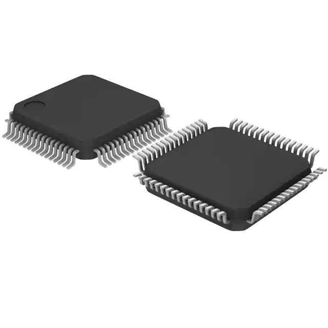
STMicroelectronics E-TDA7512F
- Part No.:
- E-TDA7512F
- Manufacturer:
- STMicroelectronics
- Category:
- RF Receivers
- Package:
- 64-LQFP
- Datasheet:
-
 E-TDA7512F.pdf
- Description:
- RF RECEIVER AM/FM 64LQFP
- Quantity:
- Payment:

- Shipping:

Inventory:4,426
Please send an inquiry. Send us your inquiry, and we will respond immediately.
Product details
Overview
E-TDA7512F from STMicroelectronics is a BiCMOS FM car-radio tuner IC integrating RF/IF mixer, dual-stage IF amplifiers (10.7 MHz and 450 kHz), fully integrated quadrature FM demodulator with noise cancellation, ISS-based adjacent-channel rejection, RDS-capable fast PLL synthesizer, and I²C-controlled quality detection (field strength, multipath, deviation, adjacent channel). It operates across global FM bands with VCO tuning range and supports electronic alignment in automotive head units.
For engineers reviewing the E-TDA7512F datasheet, E-TDA7512F pinout, E-TDA7512F application, or E-TDA7512F equivalent, key selection criteria include its 450 kHz ISS filter bandwidth programmability (30/80/120 kHz), I/Q image rejection ratio (40–46 dB), 10.7 MHz IF gain control (9–15 dB per stage), soft mute timing control, and analog quality detector outputs (FSU, FSW, ADJCH, MP) for real-time signal integrity monitoring.
Technical Context
The E-TDA7512F implements a two-stage heterodyne architecture: first conversion to 10.7 MHz using an I/Q mixer with programmable gain and phase adjustment (±7°, ±1%), followed by second conversion to 450 kHz via a limiter-integrated mixer and a digitally configurable bandpass filter. Its ISS system dynamically selects one of three internal 450 kHz filter bandwidths (30 kHz weather band, 80 kHz narrow, 120 kHz wide) based on adjacent channel and multipath detection outputs.
Control and diagnostics are fully I²C-managed, with 25 addressable registers governing PLL counters, AGC time constants (V10, V20), ISS filter mode (ISS80/ISS30), soft mute thresholds (V42), and demodulator fine-tuning (Addr 17, 25). The chip delivers analog quality signals-unweighted field strength (V14), weighted field strength (V35), adjacent channel flag (V13), and multipath indicator (V34)-all referenced to 0–4.9 V output swing with defined load impedances.
Key Specifications
| Parameter | Value and Actual Design Meaning |
|---|---|
| IF Frequencies | 10.7 MHz (1st IF) and 450 kHz (2nd IF) - enables high-selectivity double-conversion FM reception with image rejection and flexible filtering. |
| I/Q Image Rejection | 40–46 dB - achieved via on-chip gain/phase trim (±1%, ±7°), directly reducing image interference without external calibration. |
| ISS Filter Bandwidths | 30 kHz (weather band), 80 kHz (narrow), 120 kHz (wide) - selectable via register Addr 8 to adapt selectivity to local channel spacing and noise conditions. |
| IF Gain Range | 9–15 dB per stage (IF1AMP1/2) - programmable analog gain control enables optimal dynamic range management across weak/strong signal environments. |
| Quality Detector Outputs | V14 (field strength, 0.1–4.9 V), V35 (weighted field strength), V13 (adjacent channel flag), V34 (multipath flag) - provide real-time analog metrics for automatic station search and audio muting logic. |
| Supply Voltages | VCC1/VCC2/VCC3/VCCVCO = 7.5–10 V - single-supply operation simplifies power design while maintaining RF/analog/digital domain isolation. |
| Interface | I²C bus (SDA/SCL, hardwired address via Pin 41) - enables full configuration and readback of 25+ registers including PLL counters, AGC, ISS, and mute controls. |
Pinout & Package
LQFP64 package (10 mm × 10 mm, 0.5 mm pitch) with exposed thermal pad; RoHS-compliant, moisture sensitivity level 3.
| Pin/Terminal | Circuit Role | Design Meaning |
|---|---|---|
| 25 SDA, 26 SCL | I²C bidirectional data/clock | Primary configuration interface; supports register write/read for all functional blocks including PLL, ISS, AGC, and quality detectors. |
| 13 ADJCH, 34 MP, 14 FSU, 35 FSW | Analog quality detector outputs | Provide voltage-level indicators for adjacent channel presence (0.1–4.9 V), multipath distortion, unweighted/weighted field strength - used for search stop, auto-muting, and display scaling. |
| 24 SSTOP, 42 MUTETC | Digital control/status outputs | SSTOP asserts low when IF counter detects valid station lock; MUTETC sets soft mute decay time constant via external RC network. |
| 45–46 MIX2IN1/2, 7–9 MIX1IN1/2, 63–64 MIX1OUT1/2 | Differential RF/IF signal paths | Support balanced 10.7 MHz I/Q mixer input/output and 450 kHz mixer input; require 330 Ω termination and differential layout for optimal image rejection. |
| 50 IF1AMP2OUT, 54 IF1AMP1OUT, 60 IFAGCIN | IF amplifier outputs & AGC feedback | Deliver amplified 10.7 MHz signals to downstream stages; IFAGCIN accepts external AGC voltage to control gain dynamically during strong-signal conditions. |
Key Features
| Feature | Design Value |
|---|---|
| Intelligent Selectivity System (ISS) | Three-bandwidth (30/80/120 kHz), digitally switched 450 kHz IF filter that reduces adjacent-channel interference and noise without manual tuning. |
| I/Q Mixer with Trim | On-die gain (±1%) and phase (±7°) adjustment registers (Addr 29, 21) enable >40 dB image rejection after factory calibration - eliminates discrete trimmer components. |
| RDS-Capable Fast PLL | High-speed three-state phase comparator and charge pump (Addr 9–11, 22–24) support stable 100 kHz channel spacing and rapid station search for RDS data decoding. |
| Integrated Quality Detection | Four independent analog outputs (field strength, adjacent channel, multipath, deviation) provide real-time signal health metrics - enables adaptive audio processing and UI feedback. |
| Fully Electronic Alignment | All critical parameters (tank adjust, XTAL offset, demod fine-tune, AGC TC) controlled via I²C registers (Addr 20, 19, 17, 10) - removes need for manual potentiometers or test equipment during production. |
Applications
| Automotive FM Head Unit | Aftermarket Radio Tuner Module |
|---|---|
Use Scenario: Integrated into OEM dashboard infotainment systems requiring robust FM reception under varying antenna conditions and vehicle electrical noise. IC Role / Device Role / Timing Role: Primary FM tuner IC handling RF-to-audio signal chain, PLL frequency synthesis, and real-time signal quality assessment for automatic station selection and audio muting. Use Value: ISS filter adapts bandwidth to regional channel spacing (e.g., 200 kHz EU vs. 100 kHz US), while analog quality outputs feed MCU-based UI and audio DSP for seamless user experience. |
Use Scenario: Used in plug-and-play aftermarket radio modules where compact size, minimal external components, and software-configurable tuning are critical. IC Role / Device Role / Timing Role: Standalone FM front-end providing complete IF processing, demodulation, and diagnostic outputs - replaces multi-chip solutions with single LQFP64 footprint. Use Value: Fully electronic alignment via I²C eliminates factory calibration steps; soft mute (V42) and search stop (V24) signals simplify host MCU firmware development. |
| Marine VHF/FM Receiver | Weather Band Radio System |
Use Scenario: Deployed in marine communication receivers needing reliable FM reception despite salt-corrosion degraded antennas and high ambient RF noise. IC Role / Device Role / Timing Role: FM tuner with enhanced adjacent-channel rejection and multipath immunity - processes weak signals in coastal multipath environments. Use Value: Multipath detector (V34) and adjacent channel flag (V13) allow host processor to suppress distorted audio; ISS 30 kHz mode improves SNR in narrowband maritime channels. |
Use Scenario: Embedded in NOAA weather alert radios requiring dedicated 162 MHz band reception with high sensitivity and false-alarm immunity. IC Role / Device Role / Timing Role: FM tuner configured for 162.4–162.55 MHz weather band using VCO tuning range and ISS 30 kHz filter for maximum adjacent-channel rejection. Use Value: ISS30 mode (Addr 8) activates 30 kHz bandwidth - suppresses interference from nearby commercial FM stations while preserving weather tone fidelity. |
Equivalent & Alternatives
The following parts are listed as comparable options for similar FM tuner IC applications.
| Alternative Part | Technical Difference | Application Difference | Selection Advice |
|---|---|---|---|
| Si4707-B20-GM | Software-defined radio (SDR) architecture with digital IF processing; lacks analog quality detector outputs and ISS filter; requires external microcontroller for demodulation. | Used in portable battery-powered devices where ultra-low power (<10 mA) and small BGA footprint are prioritized over analog diagnostic flexibility. | Select when digital audio path integration and firmware-upgradable features outweigh need for analog signal health monitoring. |
| TDA7511F | Predecessor with fixed 450 kHz filter (no ISS bandwidth switching); no I/Q mixer - lower image rejection (32 dB typical); fewer quality detection outputs (no multipath flag). | Suitable for cost-sensitive automotive radios where basic FM performance suffices and regional channel spacing is uniform. | Choose only for legacy redesigns where PCB layout and firmware changes must be minimized; lacks ISS adaptability and RDS-optimized PLL speed. |
Compared with Si4707-B20-GM and TDA7511F, the E-TDA7512F uniquely combines analog quality telemetry, hardware-accelerated ISS filtering, and I/Q image rejection in a single BiCMOS die - enabling higher FM reception reliability in electrically noisy automotive and marine environments without added DSP overhead.
Availability
E-TDA7512F is available at Aetrix Electronics and suitable for automotive infotainment systems, aftermarket radio modules, marine VHF receivers, and NOAA weather band radios requiring stable component supply and long-term lifecycle support.
Supply support for E-TDA7512F includes scheduled delivery planning, volume procurement assistance, BOM continuity management, traceable sourcing, and lifecycle availability coordination for OEM customers, industrial embedded developers, connected-device designers, and electronics production programs.
Manufacturer
STMicroelectronics is a global semiconductor leader specializing in automotive, industrial, and consumer ICs, with broad analog, power, and microcontroller portfolios.
The TDA7512F belongs to ST's automotive-grade tuner IC product line, designed specifically for high-reliability FM radio reception in vehicles and mobile platforms where electromagnetic resilience, thermal stability, and analog signal integrity are critical.
FAQ
What is the function of Pins 1–5, 30, 38–40, and 43 on the E-TDA7512F?
These pins are designated "nu" (not used) or "nc" (no connect) in the official datasheet and must be left unconnected or tied to VCC2 as specified. Pin 55 and 56 are explicitly required to connect to VCC2; floating them risks instability. No internal circuitry connects to these terminals, and routing traces to them provides no functional benefit.
How does the ISS filter bandwidth selection work, and which register controls it?
The ISS filter bandwidth is selected via register Addr 8 (ISS filter control byte), where bit 7 (ISS80) and bit 6 (ISS30) determine the active mode: ISS80=1 selects 80 kHz, ISS30=1 selects 30 kHz, and both low selects 120 kHz. The filter is implemented as a switched-capacitor bandpass within the 450 kHz IF path and requires no external components.
Can the E-TDA7512F decode RDS data, and what hardware support does it provide?
The E-TDA7512F does not perform RDS demodulation or decoding internally but provides essential hardware support: its fast PLL synthesizer (with three-state phase comparator and adjustable charge pump) enables precise 100 kHz channel locking, and the IF counter (controlled via Addr 13–14) generates accurate search stop signals synchronized to RDS subcarrier timing - enabling external MCU-based RDS parsing.
What is the purpose of the "soft mute" function, and how is it configured?
Soft mute gradually attenuates audio output during weak-signal or high-interference conditions to avoid audible click/pop artifacts. It is controlled by register Addr 12–13 (soft mute control bytes), with timing set by external RC network on Pin 42 (MUTETC); the IC outputs analog mute ramp voltage, not digital on/off, allowing smooth transition managed by external audio amplifier.
E-TDA7512F Specifications
- Product attributes
- Attribute value
- Manufacturer:
- STMicroelectronics
- Series:
- -
- Package/Case:
- 64-LQFP
- Packaging:
- Tray
- Product Status:
- Obsolete
- Frequency:
- -
- Sensitivity:
- -
- Data Rate (Max):
- -
- Modulation or Protocol:
- AM, FM
- Applications:
- Audio
- Current - Receiving:
- 70mA
- Data Interface:
- PCB, Surface Mount
- Memory Size:
- -
- Antenna Connector:
- PCB, Surface Mount
- Features:
- -
- Voltage - Supply:
- 7.5V ~ 10V
- Operating Temperature:
- -40°C ~ 85°C
- Grade:
- Automotive
- Qualification:
- -
- Mounting Type:
- Surface Mount
- Supplier Device Package:
- 64-TQFP (10x10)
E-TDA7512F FAQ
1.How can I place an order for E-TDA7512F through Aetrix?
Please submit a Request for Quotation (RFQ) for E-TDA7512F on Aetrix. Our sales agent will provide a competitive quotation and guide you through the order confirmation once you accept the terms.
2.Are the price and stock information for E-TDA7512F reliable?
The price and inventory of E-TDA7512F are updated periodically and may fluctuate due to market conditions. Stock and pricing data are typically refreshed every 24 hours. Quotation validity for E-TDA7512F is usually 5 days.
3.What payment methods are accepted for E-TDA7512F?
We accept Wire Transfer, PayPal, Credit Card, Western Union, MoneyGram, and Escrow for E-TDA7512F transactions.
Note: Certain payment methods may incur a processing fee.
4.How is shipping managed for E-TDA7512F?
E-TDA7512F orders can be shipped via leading logistics carriers, including DHL, UPS, FedEx, TNT, or Registered Mail.
Once your E-TDA7512F order is processed, you will receive an email with the shipment details and tracking number.
Note: Tracking information may take up to 24 hours to appear. Express delivery typically takes 3–5 business days.
5.How can I obtain technical support or documentation for E-TDA7512F?
For technical support, including E-TDA7512F datasheets, pinout diagrams, or application guidance, please contact our engineering support team. They can provide detailed documentation and assistance for your E-TDA7512F requirements.
6.How does Aetrix verify that E-TDA7512F is sourced from the original manufacturer or authorized distributors?
All E-TDA7512F products on Aetrix are procured from qualified distributors and authorized channels. Our dedicated quality assurance team conducts strict verification, including traceability checks and, if necessary, third-party testing. This ensures that E-TDA7512F meets industry standards.
7.What is the process for return or replacement of E-TDA7512F?
All E-TDA7512F units undergo pre-shipment inspection (PSI). If there is an issue with E-TDA7512F, returns or replacements are accepted under the following conditions:
1.Quantity discrepancies, incorrect items, or visible external defects (such as breakage or corrosion), acknowledged by Aetrix.
2.The issue is reported within 90 days of delivery.
3.The E-TDA7512F part is unused and in its original packaging.
Return procedure for E-TDA7512F:
1.Submit a request within 90 days.
2.Obtain a Return Material Authorization (RMA) from Aetrix.
E-TDA7512F Tags
-
MICRF220AYQS-TR
Microchip Technology
-
SX1239IMLTRT
Semtech Corporation

-
SI4356-B1A-FMR
Silicon Labs

-
SI4362-C2A-GMR
Silicon Labs

-
MAX1473EUI+T
Analog Devices Inc./Maxim Integrated

-
CMX992Q3
CML Micro

-
CMX994AQ4
CML Micro

-
MAX2112ETI+
Analog Devices Inc./Maxim Integrated
-
MAX2112ETI+T
Analog Devices Inc./Maxim Integrated
-
TESEO-LIV3R
STMicroelectronics
-
M20048-1
Antenova
-
CMX994EQ4
CML Micro
Tech Hub

Operational amplifier guide covering op amp basics, feedback, ideal vs real op amps, common configurations, buffer circuits, offset, bias current, gain-bandwidth, slew rate, rail-to-rail limits and sel…

Jumper cables guide covering safe connection order, red and black clamp placement, final ground connection, cable gauge, length, clamp quality, copper vs CCA cables, jump starter comparison and battery…

LDO regulator guide covering low dropout voltage, power dissipation, thermal design, PSRR, output noise, capacitor stability, adjustable LDO circuits, LDO vs buck converter and datasheet selection chec…

Conditional Access Module guide covering CAM meaning, CI/CI+ interface, smart card authorization, DVB security workflow, TV and set-top box compatibility, internal electronics, ESD protection, connecto…

Guide to electronic component obsolescence covering EOL risk, PCN/PDN notices, last-time buy planning, replacement options, form-fit-function validation, counterfeit risk and BOM lifecycle management.

18650 battery guide covering lithium-ion cell basics, 3.6V/3.7V voltage, 4.2V charging, mAh and Wh capacity, protected cells, chargers, BMS, series-parallel packs, holders, welding and sourcing checks.…

Hall effect sensor guide covering working principle, linear and digital sensors, Arduino circuits, current sensing, speed detection, automotive applications, A3144 examples, signal filtering and datash…

Product Change Notification guide for electronic components, covering PCN meaning, PCN vs PDN/EOL, common change types, risk levels, form-fit-function review, engineering validation, BOM control, LTB/L…

A practical guide to blend door actuators, covering HVAC function, symptoms, location, AC and heater issues, reset and calibration, replacement cost, electrical diagnosis, compatibility checks, and rep…

Engineering guide to Raspberry Pi alternatives, covering chip-level differences, Orange Pi, ROCK, Jetson, Banana Pi, NanoPi, Compute Module, Pico, GPIO, camera, HAT compatibility, and replacement risks…


