
 My Inquiry
 My Account


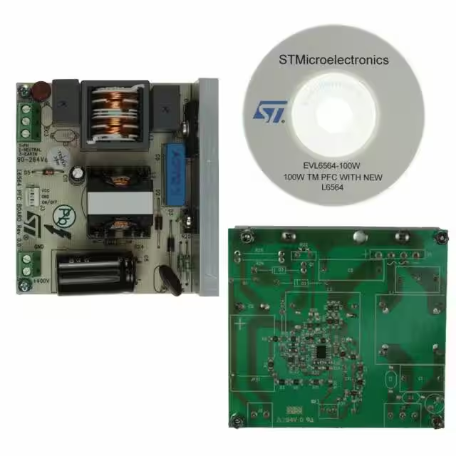
STMicroelectronics EVL6564-100W
- Part No.:
- EVL6564-100W
- Manufacturer:
- STMicroelectronics
- Package:
- Datasheet:
-
 EVL6564-100W.pdf
- Description:
- EVAL BOARD FOR L6564
- Quantity:
- Payment:

- Shipping:

Inventory:2,779
Please send an inquiry. Send us your inquiry, and we will respond immediately.
Product details
Overview
EVL6564-100W from STMicroelectronics is a demonstration board implementing the L6564 10-pin transition-mode (TM) PFC controller in SSOP10 package, delivering 100 W with wide-range mains input (85–265 VAC), <3% THD at full load, and compliance to EN61000-3-2 Class D and JEITA-MITI standards. It features bidirectional 1/V² voltage feed-forward, adjustable overvoltage protection (OVP), and integrated inductor saturation detection for robust boost-stage operation.
For engineers reviewing the EVL6564-100W datasheet, EVL6564-100W application circuit, EVL6564-100W schematic, or EVL6564-100W evaluation board layout, this page provides verified pin-level interface details, measured performance data (input current waveform, efficiency, OVP response), thermal behavior under 100 W load, and design guidance for adapting the reference topology to 85–265 VAC AC-DC adapters, LED drivers, and server auxiliary supplies.
Technical Context
The EVL6564-100W implements a fixed-off-time transition-mode PFC preregulator using the L6564 IC, where zero-current detection (ZCD) on pin 7 triggers MOSFET turn-on, and current-sense comparator (CS) on pin 4 determines turn-off based on sensed source current. The 1/V² feed-forward path-via MULT (pin 3) and VFF (pin 5)-linearizes gain across line voltage, enabling stable THD <3% from 85 VAC to 265 VAC at 100 W output.
Protection functions are hardware-verified: OVP latches off at PFC_OK >2.5 V (pin 6), brownout disables at VFF <0.8 V (restarting at >0.88 V), and inductor saturation halts switching when CS exceeds 1.7 V (pin 4). The totem-pole gate driver (pin 9) delivers −600/+800 mA into a 12 V-clamped output, directly driving 600 V/2 A MOSFETs without external buffers.
Key Specifications
| Parameter | Value and Actual Design Meaning |
|---|---|
| Output Power | 100 W continuous, validated at 85–265 VAC, 50/60 Hz, with 385 VDC nominal output |
| THD Performance | <3% at full load (100 W), meeting EN61000-3-2 Class D and JEITA-MITI limits |
| Input Voltage Range | 85–265 VAC, supported by bidirectional 1/V² feed-forward and brownout detection (VFF threshold: 0.8 V) |
| OVP Response | Latched shutdown at PFC_OK >2.5 V; restarts only after VCC cycle or PFC_OK falls below 2.4 V |
| Gate Drive Capability | −600 mA / +800 mA peak, 12 V clamped output (pin 9), sufficient for direct drive of STP16NF06L or similar MOSFETs |
| Inductor Saturation Detection | Hardware-comparator trip at CS >1.7 V (pin 4), initiating safe shutdown before core saturation damages MOSFET |
| Efficiency | 93.5% typical at 100 W, 230 VAC, measured per Figure 35–36 in DocID16202 Rev 5 |
Availability
EVL6564-100W is available at Aetrix Electronics and suitable for high-efficiency AC-DC adapter development, LED luminaire power supply qualification, and EN61000-3-2 compliance testing requiring stable component supply and documented reference design validation.
Supply support for EVL6564-100W includes scheduled delivery planning, volume procurement assistance, BOM continuity management, traceable sourcing, and lifecycle availability coordination for OEM customers, industrial embedded developers, connected-device designers, and electronics production programs.
Manufacturer
STMicroelectronics is a global semiconductor leader headquartered in Geneva, Switzerland, designing and manufacturing analog, microcontroller, power, and sensor solutions for industrial, automotive, and consumer applications.
The EVL6564-100W belongs to ST's Power Management Evaluation Board product line, engineered to accelerate time-to-compliance for PFC designs targeting IEC61000-3-2, JEITA-MITI, and ENERGY STAR requirements in sub-200 W systems.
FAQ
What input voltage range does the EVL6564-100W support?
The EVL6564-100W supports universal AC input from 85 VAC to 265 VAC, 47–63 Hz, as confirmed by test data in Figures 37–38 of DocID16202 Rev 5. Its L6564 controller uses bidirectional 1/V² feed-forward and brownout detection (VFF pin threshold: 0.8 V) to maintain stable operation and <3% THD across this full range without manual reconfiguration.
Does the board include overvoltage protection, and how does it behave?
Yes - the EVL6564-100W implements latched overvoltage protection via the PFC_OK pin (pin 6) of the L6564. When the divided output voltage exceeds 2.5 V, the controller stops switching and remains latched until VCC is cycled below 6 V or the PFC_OK voltage falls below 2.4 V, preventing sustained overvoltage stress on the bulk capacitor and downstream DC-DC stage.
Can the EVL6564-100W be used to evaluate inductor saturation protection?
Yes - the board validates the L6564's hardware-based inductor saturation detection. When the current sense voltage (CS pin 4) exceeds 1.7 V, the IC immediately halts switching, enters a safe idle state, and resumes only after the fault clears and the start-up timer expires (150–600 µs). This behavior is documented in Section 6.5 and Figure 32 of the datasheet.
Is the EVL6564-100W compatible with standard 100 W LED driver requirements?
Yes - the board delivers 385 VDC at 100 W with <3% THD and 93.5% efficiency, matching key requirements for commercial LED luminaires. Its wide-input operation (85–265 VAC), EN61000-3-2 Class D compliance, and built-in protections (OVP, brownout, saturation) make it suitable for evaluating constant-voltage LED driver front-ends, especially where high PF (>0.98) and low harmonic distortion are mandated.
EVL6564-100W Specifications
- Product attributes
- Attribute value
- Manufacturer:
- STMicroelectronics
- Series:
- -
- Packaging:
- Box
- Product Status:
- Active
- Main Purpose:
- AC/DC, Primary Side
- Outputs and Type:
- 1 Non-Isolated Output
- Voltage - Output:
- 100 W
- Current - Output:
- 400V
- Voltage - Input:
- -
- Regulator Topology:
- 90 ~ 265 VAC
- Frequency - Switching:
- Boost
- Contents:
- 40kHz
- Utilized IC / Part:
- Board(s)
- Power - Output:
- L6564
EVL6564-100W FAQ
1.How can I place an order for EVL6564-100W through Aetrix?
Please submit a Request for Quotation (RFQ) for EVL6564-100W on Aetrix. Our sales agent will provide a competitive quotation and guide you through the order confirmation once you accept the terms.
2.Are the price and stock information for EVL6564-100W reliable?
The price and inventory of EVL6564-100W are updated periodically and may fluctuate due to market conditions. Stock and pricing data are typically refreshed every 24 hours. Quotation validity for EVL6564-100W is usually 5 days.
3.What payment methods are accepted for EVL6564-100W?
We accept Wire Transfer, PayPal, Credit Card, Western Union, MoneyGram, and Escrow for EVL6564-100W transactions.
Note: Certain payment methods may incur a processing fee.
4.How is shipping managed for EVL6564-100W?
EVL6564-100W orders can be shipped via leading logistics carriers, including DHL, UPS, FedEx, TNT, or Registered Mail.
Once your EVL6564-100W order is processed, you will receive an email with the shipment details and tracking number.
Note: Tracking information may take up to 24 hours to appear. Express delivery typically takes 3–5 business days.
5.How can I obtain technical support or documentation for EVL6564-100W?
For technical support, including EVL6564-100W datasheets, pinout diagrams, or application guidance, please contact our engineering support team. They can provide detailed documentation and assistance for your EVL6564-100W requirements.
6.How does Aetrix verify that EVL6564-100W is sourced from the original manufacturer or authorized distributors?
All EVL6564-100W products on Aetrix are procured from qualified distributors and authorized channels. Our dedicated quality assurance team conducts strict verification, including traceability checks and, if necessary, third-party testing. This ensures that EVL6564-100W meets industry standards.
7.What is the process for return or replacement of EVL6564-100W?
All EVL6564-100W units undergo pre-shipment inspection (PSI). If there is an issue with EVL6564-100W, returns or replacements are accepted under the following conditions:
1.Quantity discrepancies, incorrect items, or visible external defects (such as breakage or corrosion), acknowledged by Aetrix.
2.The issue is reported within 90 days of delivery.
3.The EVL6564-100W part is unused and in its original packaging.
Return procedure for EVL6564-100W:
1.Submit a request within 90 days.
2.Obtain a Return Material Authorization (RMA) from Aetrix.
EVL6564-100W Tags
-
DFR0571
DFRobot
-
DFR0379
DFRobot
-
DFR0205
DFRobot
-
1385
Adafruit Industries LLC
-
COM-15208
SparkFun Electronics
-
1944
Adafruit Industries LLC
-
2465
Adafruit Industries LLC
-
DC2468A
Analog Devices Inc.
-
DC2841A
Analog Devices Inc.

-
TPS552892EVM-111
Texas Instruments
-
TPS55289EVM-093
Texas Instruments
-
EPC9158
EPC
Tech Hub

A practical engineering and sourcing framework covering lifecycle verification, lifetime-buy calculations, replacement qualification, supplier checks and counterfeit-risk controls.

TTL and CMOS logic families differ in thresholds, loading, output drive, power and timing. This engineering guide compares 74HC and 74HCT, calculates noise margins and checks 3.3 V/5 V compatibility.

A practical engineering guide to 3.3V and 5V logic compatibility, input thresholds, resistor dividers, translator ICs, MOSFET level shifting, I2C pull-ups, timing limits and power-sequencing risks.

The 74HC595 uses push-pull logic outputs, while the TPIC6B595 uses 50 V open-drain DMOS sinks for higher-power loads. This guide compares timing, current limits, 3.3 V interfacing, load wiring, thermal…

The 74HC595 converts serial data into eight stable parallel outputs. This guide covers pin functions, shift and storage timing, OE and MR behavior, drive-current limits, cascading, voltage compatibilit…

A technical comparison of level-sensitive latches and edge-triggered flip-flops, covering timing windows, setup and hold limits, master–slave operation, time borrowing, race-through, HDL inference and…

A D latch stores one bit while Enable controls when data can pass. This reference covers gate-level operation, truth tables, transparency, setup and hold timing, LE versus OE, common ICs and practical …

An SR latch stores one bit through cross-coupled feedback. This engineering reference covers NOR and NAND implementations, truth tables, forbidden-state recovery, gated operation, switch debouncing, fa…

Latch circuits retain one bit through feedback. This technical reference covers SR and D latches, truth tables, transparency, timing limits, latch-versus-flip-flop behavior, applications and common log…

An engineering guide to LED driver operation, constant-current and constant-voltage outputs, linear and switching topologies, dimming, IC selection, calculations, replacement compatibility, and fault c…


