
 My Inquiry
 My Account


STMicroelectronics EVLVIP16L-4WFL
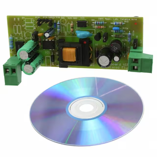
- Part No.:
- EVLVIP16L-4WFL
- Manufacturer:
- STMicroelectronics
- Package:
- Datasheet:
-
 EVLVIP16L-4WFL.pdf
- Description:
- EVAL BOARD FOR VIPER16
- Quantity:
- Payment:

- Shipping:

Inventory:1,086
Please send an inquiry. Send us your inquiry, and we will respond immediately.
Product details
Overview
EVLVIP16L-4WFL from STMicroelectronics is a fixed-frequency, off-line AC-DC converter IC integrating an 800 V avalanche-rugged power MOSFET, PWM controller, adjustable overcurrent limit, hysteretic thermal shutdown, and on-board soft-start. It delivers up to 10 W in open-frame designs at 50 °C ambient, operates at 60 kHz with ±4 kHz frequency jittering for EMI reduction, and achieves <30 mW standby power at 230 VAC - enabling capacitive supply replacement in auxiliary power supplies for smart meters and LED drivers.
For engineers reviewing the EVLVIP16L-4WFL datasheet, EVLVIP16L-4WFL pinout, EVLVIP16L-4WFL application, or EVLVIP16L-4WFL equivalent, this device is selected for low-component-count, self-biased flyback/buck-boost converters requiring high-voltage ruggedness, burst-mode efficiency compliance (e.g., Energy Star Level VI), and integrated fault recovery without auxiliary winding.
Technical Context
The EVLVIP16L-4WFL implements a current-mode PWM architecture with cycle-by-cycle drain current sensing via internal SenseFET, where the COMP pin voltage directly modulates peak current limit against a reference derived from FB. Its oscillator uses fixed 60 kHz center frequency with 230 Hz spread-spectrum modulation (±4 kHz) to suppress harmonic peaks.
Power delivery relies on high-voltage startup from DRAIN (40–60 V threshold), followed by self-supply via internal HV current generator during MOSFET off-time; VDD regulation (11.5–23.5 V) enables operation without auxiliary winding. Protection includes auto-restart after overload (50 ms timeout, 1 s restart delay), open-loop failure detection, and thermal shutdown at 150–160 °C with 30 °C hysteresis.
Key Specifications
| Parameter | Value and Actual Design Meaning |
|---|---|
| Operating Frequency | 60 kHz ±4 kHz - fixed center with jittering reduces EMI filter cost and simplifies compliance testing. |
| Drain Voltage Rating | 800 V - enables direct rectified mains connection (85–265 VAC) without external HV MOSFET or snubber. |
| Standby Power | <30 mW at 230 VAC - meets strict no-load energy regulations (e.g., EU CoC Tier 2, DOE Level VI). |
| Current Limit | 0.4 A typical (adjustable via LIM pin resistor) - sets primary-side OCP threshold for transformer and diode stress control. |
| Soft-Start Time | 8.5 ms - limits inrush current and prevents transformer saturation during cold start or fault recovery. |
| Burst Mode Threshold | VCOMP ≤ 1.1 V (with 40 mV hysteresis) - triggers ultra-low-power mode to maintain regulation under light loads. |
| Thermal Shutdown | 150–160 °C with 30 °C hysteresis - ensures safe derating and automatic recovery without external thermal sensor. |
Pinout & Package
Package: SO16 narrow (16-pin, 0.150" wide body, exposed thermal pad). Pin layout optimized for heat dissipation: DRAIN pins (13–16) are internally connected to metal frame and require copper pour beneath for thermal management.
| Pin/Terminal | Circuit Role | Design Meaning |
|---|---|---|
| GND (Pins 1–2) | Controller ground reference | Source node for internal MOSFET and error amplifier - must be low-impedance connection to PCB ground plane. |
| VDD (Pin 5) | Control section supply | Charges external capacitor; clamped at 23.5 V - powers logic, gate driver, and protection circuits. |
| LIM (Pin 6) | Adjustable current limit input | Sinks current to reduce default 0.4 A OCP threshold; open-circuit = full rating; resistor sets precise trip point. |
| FB (Pin 7) | Inverting error amplifier input | Accepts feedback voltage; internal 3.3 V reference enables single-resistor output sensing (non-isolated) or opto-coupler interface (isolated). |
| COMP (Pin 8) | Error amplifier output | Drives RC compensation network; linear range 1.1–3.0 V - used for loop stability and opto-transistor control in isolated topologies. |
| DRAIN (Pins 13–16) | High-voltage power switch drain | Carries full primary current and HV startup current; thermally bonded to package frame - requires dedicated copper area for heatsinking. |
Key Features
| Feature | Design Value |
|---|---|
| No auxiliary winding required | Internal HV current generator draws startup and operating bias directly from DRAIN - eliminates transformer auxiliary winding and associated rectifier/capacitor. |
| Frequency jittering | ±4 kHz modulation at 230 Hz spreads switching energy across spectrum - reduces peak EMI by >10 dB and eases EN55022 Class B filtering. |
| Safe auto-restart | Integrated up-down counter disables switching after 50 ms overload, then initiates soft-start after 1 s - prevents thermal runaway while maintaining system availability. |
| Hysteretic thermal protection | Shuts down at 150–160 °C junction temperature and re-enables only after 30 °C cooldown - avoids oscillatory tripping near thermal limit. |
| Burst mode operation | Reduces average switching frequency to hundreds of Hz under light load - cuts core loss, conduction loss, and audible noise while sustaining regulation. |
Applications
| Smart Electricity Meters | LED Lighting Drivers |
|---|---|
|
Use Scenario: Primary-side auxiliary power supply in DIN-rail mounted smart meters, operating continuously from 85–265 VAC mains with no fan cooling. IC Role / Device Role / Timing Role: Off-line flyback controller providing isolated 12 V/100 mA for MCU, RTC, and communication ICs - replaces discrete HV startup + PWM IC solution. Use Value: Eliminates auxiliary winding and reduces BOM count by ≥4 components while meeting IEC 62053-21 surge immunity (6 kV) via 800 V MOSFET ruggedness. |
Use Scenario: Non-isolated buck-boost LED driver for commercial downlights, delivering constant current to 12–24 V LED strings from universal AC input. IC Role / Device Role / Timing Role: Self-biased AC-DC converter regulating output via FB pin feedback - operates in discontinuous conduction mode with inherent short-circuit protection. Use Value: Achieves <30 mW no-load consumption and 85% efficiency at 70% load - satisfies ENERGY STAR SSL V2.1 standby and efficacy requirements. |
| Home Appliance Control Boards | Industrial Sensor Power Supplies |
|
Use Scenario: Auxiliary 5 V/200 mA supply on washing machine main control board, sharing same AC input as motor drive stage. IC Role / Device Role / Timing Role: Integrated HV switch + controller powering microcontroller, display, and relay drivers - withstands line transients from motor commutation. Use Value: 800 V avalanche rating absorbs 1.2/50 μs surges up to 2 kV without external TVS, reducing footprint and cost versus discrete solutions. |
Use Scenario: Compact 24 V/100 mA isolated power supply for fieldbus sensors in factory automation, mounted on space-constrained PCBs. IC Role / Device Role / Timing Role: Flyback controller with primary-side regulation using optocoupler feedback - supports wide input (85–265 VAC) and maintains regulation across -40 to +85 °C ambient. Use Value: On-chip soft-start and auto-restart prevent latch-up during brownouts common in industrial environments - improves system uptime vs. non-recovering controllers. |
Equivalent & Alternatives
The following parts are listed as comparable options for similar off-line AC-DC converter applications.
| Alternative Part | Technical Difference | Application Difference | Selection Advice |
|---|---|---|---|
| VIPER22ADIP | Higher 22 W output capability, 730 V MOSFET, 60 kHz fixed frequency, but no frequency jittering or burst mode. | Targeted at higher-power adapters; lacks EMI-reduction features critical for compact enclosed designs. | Select when >10 W continuous output is needed and EMI filtering budget allows larger components. |
| ICE3B0565J | Fixed 65 kHz frequency, 650 V MOSFET, integrated X-cap discharge, but requires auxiliary winding and has higher standby power (~100 mW). | Designed for cost-sensitive consumer adapters; not suitable for ultra-low-standby or auxiliary-winding-free designs. | Choose for legacy designs where auxiliary winding exists and EMI requirements are less stringent. |
Compared with VIPER22ADIP and ICE3B0565J, EVLVIP16L-4WFL uniquely combines 800 V ruggedness, jittering, burst mode, and zero-auxiliary-winding operation - making it optimal for space- and efficiency-constrained auxiliary supplies where reliability under transient stress is critical.
Availability
EVLVIP16L-4WFL is available at Aetrix Electronics and suitable for smart metering, LED lighting drivers, home appliance control boards, and industrial sensor power supplies requiring stable component supply, long-term lifecycle support, and consistent parametric performance across production batches.
Supply support for EVLVIP16L-4WFL includes scheduled delivery planning, volume procurement assistance, BOM continuity management, traceable sourcing, and lifecycle availability coordination for OEM customers, industrial embedded developers, connected-device designers, and electronics production programs.
Manufacturer
STMicroelectronics is a global semiconductor leader headquartered in Geneva, Switzerland, designing and manufacturing microcontrollers, power ICs, sensors, and analog devices for automotive, industrial, and consumer markets.
EVLVIP16L-4WFL belongs to the VIPer™ plus family - a series of highly integrated AC-DC converters engineered specifically for low-power auxiliary supplies where simplicity, safety, and regulatory compliance are prioritized over programmability or multi-topology flexibility.
FAQ
What is the maximum continuous output power of EVLVIP16L-4WFL in an open-frame design?
EVLVIP16L-4WFL delivers up to 10 W continuous output power in open-frame configurations at 50 °C ambient temperature with adequate heat sinking, as confirmed in Table 2 of the official datasheet (DocID15232 Rev 7). This assumes proper PCB copper area under DRAIN pins and standard FR4 layout per Section 16 guidelines.
Can EVLVIP16L-4WFL operate without an auxiliary winding?
Yes - EVLVIP16L-4WFL integrates a high-voltage current generator that draws startup and operating bias directly from the DRAIN pin, eliminating the need for an auxiliary winding. This is validated in Sections 7 and 8 of the datasheet, where self-supply operation is described for both startup and steady-state conditions.
How does the LIM pin adjust overcurrent protection?
The LIM pin sinks current to lower the default 0.4 A drain current limit. Connecting a resistor RLIM between LIM and GND sets the sunk current, which linearly reduces IDlim per Figure 13 and Section 11. Leaving LIM open retains the full 0.4 A rating; RLIM >80 kΩ yields negligible adjustment.
What thermal protection mechanism does EVLVIP16L-4WFL use?
EVLVIP16L-4WFL employs a hysteretic thermal shutdown with activation at 150–160 °C junction temperature and 30 °C hysteresis (Section 4.1, Table 4). When triggered, the power MOSFET is disabled until junction temperature drops below ~120–130 °C, preventing oscillatory tripping during sustained thermal stress.
EVLVIP16L-4WFL Specifications
- Product attributes
- Attribute value
- Manufacturer:
- STMicroelectronics
- Series:
- VIPer™ plus
- Packaging:
- Box
- Product Status:
- Active
- Main Purpose:
- AC/DC, Primary Side
- Outputs and Type:
- 1 Isolated Output
- Voltage - Output:
- 4 W
- Current - Output:
- 16V
- Voltage - Input:
- 250mA
- Regulator Topology:
- 85 ~ 265 VAC
- Frequency - Switching:
- Flyback
- Contents:
- 60kHz
- Utilized IC / Part:
- Board(s)
- Power - Output:
- VIPer16
EVLVIP16L-4WFL FAQ
1.How can I place an order for EVLVIP16L-4WFL through Aetrix?
Please submit a Request for Quotation (RFQ) for EVLVIP16L-4WFL on Aetrix. Our sales agent will provide a competitive quotation and guide you through the order confirmation once you accept the terms.
2.Are the price and stock information for EVLVIP16L-4WFL reliable?
The price and inventory of EVLVIP16L-4WFL are updated periodically and may fluctuate due to market conditions. Stock and pricing data are typically refreshed every 24 hours. Quotation validity for EVLVIP16L-4WFL is usually 5 days.
3.What payment methods are accepted for EVLVIP16L-4WFL?
We accept Wire Transfer, PayPal, Credit Card, Western Union, MoneyGram, and Escrow for EVLVIP16L-4WFL transactions.
Note: Certain payment methods may incur a processing fee.
4.How is shipping managed for EVLVIP16L-4WFL?
EVLVIP16L-4WFL orders can be shipped via leading logistics carriers, including DHL, UPS, FedEx, TNT, or Registered Mail.
Once your EVLVIP16L-4WFL order is processed, you will receive an email with the shipment details and tracking number.
Note: Tracking information may take up to 24 hours to appear. Express delivery typically takes 3–5 business days.
5.How can I obtain technical support or documentation for EVLVIP16L-4WFL?
For technical support, including EVLVIP16L-4WFL datasheets, pinout diagrams, or application guidance, please contact our engineering support team. They can provide detailed documentation and assistance for your EVLVIP16L-4WFL requirements.
6.How does Aetrix verify that EVLVIP16L-4WFL is sourced from the original manufacturer or authorized distributors?
All EVLVIP16L-4WFL products on Aetrix are procured from qualified distributors and authorized channels. Our dedicated quality assurance team conducts strict verification, including traceability checks and, if necessary, third-party testing. This ensures that EVLVIP16L-4WFL meets industry standards.
7.What is the process for return or replacement of EVLVIP16L-4WFL?
All EVLVIP16L-4WFL units undergo pre-shipment inspection (PSI). If there is an issue with EVLVIP16L-4WFL, returns or replacements are accepted under the following conditions:
1.Quantity discrepancies, incorrect items, or visible external defects (such as breakage or corrosion), acknowledged by Aetrix.
2.The issue is reported within 90 days of delivery.
3.The EVLVIP16L-4WFL part is unused and in its original packaging.
Return procedure for EVLVIP16L-4WFL:
1.Submit a request within 90 days.
2.Obtain a Return Material Authorization (RMA) from Aetrix.
EVLVIP16L-4WFL Tags
-
DFR0571
DFRobot
-
DFR0379
DFRobot
-
DFR0205
DFRobot
-
1385
Adafruit Industries LLC
-
COM-15208
SparkFun Electronics
-
1944
Adafruit Industries LLC
-
2465
Adafruit Industries LLC
-
DC2468A
Analog Devices Inc.
-
DC2841A
Analog Devices Inc.

-
TPS552892EVM-111
Texas Instruments
-
TPS55289EVM-093
Texas Instruments
-
EPC9158
EPC
Tech Hub

A practical engineering and sourcing framework covering lifecycle verification, lifetime-buy calculations, replacement qualification, supplier checks and counterfeit-risk controls.

TTL and CMOS logic families differ in thresholds, loading, output drive, power and timing. This engineering guide compares 74HC and 74HCT, calculates noise margins and checks 3.3 V/5 V compatibility.

A practical engineering guide to 3.3V and 5V logic compatibility, input thresholds, resistor dividers, translator ICs, MOSFET level shifting, I2C pull-ups, timing limits and power-sequencing risks.

The 74HC595 uses push-pull logic outputs, while the TPIC6B595 uses 50 V open-drain DMOS sinks for higher-power loads. This guide compares timing, current limits, 3.3 V interfacing, load wiring, thermal…

The 74HC595 converts serial data into eight stable parallel outputs. This guide covers pin functions, shift and storage timing, OE and MR behavior, drive-current limits, cascading, voltage compatibilit…

A technical comparison of level-sensitive latches and edge-triggered flip-flops, covering timing windows, setup and hold limits, master–slave operation, time borrowing, race-through, HDL inference and…

A D latch stores one bit while Enable controls when data can pass. This reference covers gate-level operation, truth tables, transparency, setup and hold timing, LE versus OE, common ICs and practical …

An SR latch stores one bit through cross-coupled feedback. This engineering reference covers NOR and NAND implementations, truth tables, forbidden-state recovery, gated operation, switch debouncing, fa…

Latch circuits retain one bit through feedback. This technical reference covers SR and D latches, truth tables, transparency, timing limits, latch-versus-flip-flop behavior, applications and common log…

An engineering guide to LED driver operation, constant-current and constant-voltage outputs, linear and switching topologies, dimming, IC selection, calculations, replacement compatibility, and fault c…


