
 My Inquiry
 My Account


onsemi FAN48632UC33X
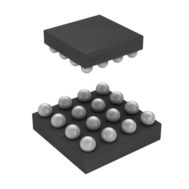
- Part No.:
- FAN48632UC33X
- Manufacturer:
- onsemi
- Category:
- Special Purpose Regulators
- Package:
- 16-UFBGA, WLCSP
- Datasheet:
-
 FAN48632UC33X.pdf
- Description:
- IC REG CONV GSM PA 1OUT 16WLCSP
- Quantity:
- Payment:

- Shipping:

Inventory:3,000
Please send an inquiry. Send us your inquiry, and we will respond immediately.
Product details
Overview
FAN48632UC33X from onsemi is a 2.5 MHz synchronous boost DC-DC converter IC optimized for GSM/EDGE power amplifier (PA) biasing, delivering up to 2.0 A peak output current at 3.3 V output with 96% efficiency, integrated MOSFETs (RDS(ON)P = 65–85 mΩ, RDS(ON)N = 85–120 mΩ), and WLCSP-16 1.78×1.78 mm package.
For engineers reviewing the FAN48632UC33X datasheet, pinout, applications, or equivalent options, key selection criteria include GSM 217 Hz pulse-load capability, VSEL-programmable 3.3 V / 3.49 V output, integrated soft-start and overvoltage protection (6.0–6.3 V), thermal shutdown at 120°C, and operation across −40°C to +85°C ambient.
Technical Context
The FAN48632UC33X employs a constant-frequency current-mode control architecture operating at 2.0–3.0 MHz (typ. 2.5 MHz), supporting both CCM and DCM modes depending on load and input conditions. It integrates high-side PMOS (65–85 mΩ), low-side NMOS (85–120 mΩ), and bypass PMOS (65–85 mΩ) switches in a single die.
Internal logic enables precise output regulation via VSEL pin selection (3.30 V / 3.49 V), programmable soft-start (600 µs), and dynamic response to GSM PA pulse loads up to 2.0 A at 217 Hz. Protection includes UVLO (2.20–2.35 V), OVP (6.0–6.3 V), OCP (3.3–4.1 A peak), and thermal shutdown with hysteresis (120°C trip / 100°C recovery).
Key Specifications
| Parameter | Value and Actual Design Meaning |
|---|---|
| Output Voltage | 3.30 V / 3.49 V (VSEL-selectable; ±4% regulation over load/temperature) |
| Switching Frequency | 2.0–3.0 MHz (typ. 2.5 MHz; enables ultra-small 0.47 µH inductor and 0603 passives) |
| Peak Output Current | 2.0 A at GSM 217 Hz pulses (VIN ≥ 2.6 V; supports PA envelope tracking) |
| Efficiency | 96% at 1 A, VIN = 3.0 V, VOUT = 3.3 V (enables minimal thermal dissipation in compact RF modules) |
| Input Voltage Range | 2.35 V to 5.5 V (supports single-cell Li-ion, Li-polymer, and NiMH battery inputs) |
| Quiescent Current | 140–190 µA (VIN = 4.2 V, VOUT = 3.5 V; extends battery life in standby) |
| Thermal Shutdown | 120°C trip / 100°C hysteresis (prevents damage during sustained high-current GSM bursts) |
Pinout & Package
Package: WLCSP-16 (1.78 × 1.78 × 0.586 mm, 0.4 mm pitch, Case 567SY). Ultra-compact wafer-level chip-scale packaging enables direct integration into space-constrained GSM/EDGE front-end modules.
| Pin/Terminal | Circuit Role | Design Meaning |
|---|---|---|
| A1 | EN | Active-high enable input; logic threshold VIH = 1.2 V, VIL = 0.4 V; enables system-level power sequencing |
| A2 | PG | Power good open-drain output; asserts low when VOUT deviates >±4% or fault occurs (OVP/OCP/thermal) |
| A3–A4 | VIN | Main input supply (2.35–5.5 V); connects to battery or PMIC output; multiple pins reduce IR drop |
| B1 | VSEL | Output voltage select; 0 V = 3.30 V, 1.2 V = 3.49 V; sets PA bias point without external resistor network |
| B2, C2, D1 | AGND | Analog ground reference; separate from PGND to minimize noise coupling into feedback path |
| B3–B4 | VOUT | Regulated output (3.3 V / 3.49 V); connects directly to GSM PA VCC pin; low-impedance path critical for pulse response |
| C1 | BYP | Bypass capacitor connection for internal LDO; stabilizes gate drive and modulator logic; requires 10 µF X5R 0603 |
| C3–C4 | SW | Switch node; connects to external 0.47 µH inductor; high dI/dt path requiring tight layout and short trace |
| D2–D4 | PGND | Power ground return for SW and output rectifier; isolated from AGND to prevent switching noise injection |
Key Features
| Feature | Design Value |
|---|---|
| GSM 217 Hz Pulse Optimization | 2.0 A peak current delivery with <80 ns turn-on time ensures stable PA bias during TDMA frame bursts |
| VSEL-Programmable Output | Two factory-trimmed output options (3.30 V / 3.49 V) selected by single logic level-no external resistors needed |
| Integrated Dual-MOSFET + Bypass Switch | PMOS high-side (65–85 mΩ), NMOS low-side (85–120 mΩ), and dedicated bypass PMOS eliminate external switch |
| Ultra-Fast Soft-Start | 600 µs programmable ramp prevents inrush current and output overshoot during PA power-up sequences |
| Comprehensive Fault Protection | UVLO, OVP (6.0–6.3 V), cycle-by-cycle OCP (3.3–4.1 A), thermal shutdown (120°C), and PG fault reporting |
Applications
| GSM Power Amplifier Bias | EDGE Transmitter Front-End |
|---|---|
|
Use Scenario: Supplies regulated 3.3 V or 3.49 V bias to Class AB/E GSM PA stages during 217 Hz TDMA frame bursts. IC Role / Device Role / Timing Role: Primary boost converter providing pulsed high-current VCC rail synchronized to PA enable timing. Use Value: Delivers 2.0 A peak current with <80 ns response, maintaining VOUT regulation within ±4% during burst transitions-critical for EVM compliance. |
Use Scenario: Powers dual-mode EDGE transmitter PAs requiring tighter output tolerance and faster transient response than GSM-only designs. IC Role / Device Role / Timing Role: High-efficiency, low-noise boost regulator with programmable VOUT and soft-start for multi-PA sequencing. Use Value: 96% efficiency at 1 A and 2.5 MHz switching minimize heat and EMI in densely packed RF modules, enabling smaller PCB area. |
| Compact Cellular IoT Modems | Low-Power Mobile Handsets |
|
Use Scenario: Provides PA supply in NB-IoT or LTE-M modules where board space and battery life are severely constrained. IC Role / Device Role / Timing Role: Space-optimized WLCSP-16 boost IC replacing discrete inductor+MOSFET solutions in sub-20 mm² RF sections. Use Value: 1.78×1.78 mm footprint and 0.47 µH inductor support miniaturized modem designs while sustaining 1.5 A continuous output. |
Use Scenario: Powers main PA in entry-level feature phones or dual-SIM handsets using single-cell Li-ion batteries (2.8–4.2 V). IC Role / Device Role / Timing Role: Battery-input boost converter with UVLO (2.20–2.35 V) and thermal management for reliable operation across full battery discharge curve. Use Value: 140–190 µA quiescent current extends standby time; PG pin enables host MCU to monitor PA rail health in real time. |
Equivalent & Alternatives
The following parts are listed as comparable options for similar boost converter applications.
| Alternative Part | Technical Difference | Application Difference | Selection Advice |
|---|---|---|---|
| TPS613222ADBVR | Fixed 3.3 V output, no VSEL option; 2.0 MHz switching; 1.5 A max continuous (vs. FAN48632UC33X's 2.0 A pulse) | Lacks GSM-specific pulse optimization and dual-VOUT selection; better suited for general-purpose 3.3 V rail generation | Select if fixed 3.3 V and lower cost outweigh need for PA-tailored pulse response and VSEL flexibility |
| MAX17222ETA+ | 3.3 V fixed output; 1.2 MHz switching; 1.0 A max output; WLP-6 package (smaller but lower current capability) | No thermal shutdown hysteresis or PG pin; lacks OVP and cycle-by-cycle OCP robustness for PA use | Choose only for ultra-low-power, non-PA applications where size is paramount and current demand ≤1.0 A |
Compared with TPS613222ADBVR and MAX17222ETA+, the FAN48632UC33X uniquely combines GSM 217 Hz pulse capability, VSEL-selectable outputs, integrated bypass switch, and comprehensive fault reporting-making it purpose-built for cellular PA biasing rather than generic boost conversion.
Availability
FAN48632UC33X is available at Aetrix Electronics and suitable for GSM/EDGE power amplifier biasing, compact cellular IoT modems, and low-power mobile handset designs requiring stable component supply, consistent WLCSP-16 sourcing, and RoHS-compliant manufacturing.
Supply support for FAN48632UC33X includes scheduled delivery planning, volume procurement assistance, BOM continuity management, traceable sourcing, and lifecycle availability coordination for OEM customers, industrial embedded developers, connected-device designers, and electronics production programs.
Manufacturer
onsemi (formerly ON Semiconductor) is a global semiconductor supplier specializing in energy-efficient silicon and power solutions for automotive, industrial, cloud, and communications markets.
The FAN48632UC33X belongs to onsemi's TINYBOOST™ family of ultra-compact, high-frequency boost converters engineered specifically for GSM/EDGE/3G/4G RF power amplifier biasing in space- and power-constrained wireless devices.
FAQ
What is the exact output voltage setting for FAN48632UC33X?
The FAN48632UC33X is factory-configured for 3.30 V nominal output with ±4% regulation tolerance. Its VSEL pin allows selection between two precision-trimmed outputs: 3.30 V (VSEL = 0 V) or 3.49 V (VSEL = 1.2 V). This dual-option design eliminates external resistor networks while ensuring accurate PA bias voltage matching across production units. The FAN48632UC33X datasheet specifies VOUT = 3.30 / 3.49 V under standard test conditions (VIN = 3.0 V, TA = 25°C).
Does FAN48632UC33X support GSM 217 Hz pulse-load operation?
Yes, the FAN48632UC33X is explicitly designed and characterized for GSM 217 Hz pulse-load operation, delivering up to 2.0 A peak output current at VOUT = 3.3 V or 3.5 V with VIN ≥ 2.6 V. Its 2.5 MHz switching frequency, fast 80 ns turn-on time, and integrated bypass PMOS ensure minimal output droop and rapid recovery during TDMA frame bursts. This capability is verified in the FAN48632UC33X datasheet Figure 9 (pulse-load efficiency) and Table 7 (IV_LIM_SS = 1.8 A).
What package type and dimensions does FAN48632UC33X use?
The FAN48632UC33X uses a WLCSP-16 (Wafer-Level Chip-Scale Package) with mechanical outline Case 567SY, measuring 1.78 × 1.78 × 0.586 mm and 0.4 mm ball pitch. It features 16 solder bumps arranged in a 4×4 grid, with pin-1 marked by an alphanumeric code (e.g., "KKXY"). This ultra-compact package enables direct placement beneath RF components in space-critical GSM/EDGE front-end modules, as confirmed in the FAN48632UC33X mechanical drawing (Document 98AON16621G).
How does the FAN48632UC33X handle overvoltage and thermal faults?
The FAN48632UC33X incorporates independent overvoltage protection (OVP) triggering at 6.0–6.3 V and thermal shutdown at 120°C with 100°C hysteresis. Upon OVP detection, the IC disables switching and asserts the PG pin low. During thermal overload, it latches off after 20 ms and remains disabled until junction temperature falls below 100°C. These protections are fully integrated-no external components required-and are validated per JEDEC JESD22-A104 reliability testing, as documented in the FAN48632UC33X datasheet Sections 4 and 10.
Is FAN48632UC33X RoHS compliant and lead-free?
Yes, the FAN48632UC33X is Pb-free, halogen-free/BFR-free, and fully RoHS compliant per EU Directive 2011/65/EU. onsemi confirms this status in the FAN48632UC33X datasheet footnote on page 1 ("These Devices are Pb−Free, Halogen Free/BFR Free and are RoHS Compliant") and maintains full material declarations through its compliance portal. The WLCSP-16 package uses matte tin (Sn) finish on all solder bumps, meeting IPC-J-STD-020 moisture sensitivity level 3 requirements.
FAN48632UC33X Specifications
- Product attributes
- Attribute value
- Manufacturer:
- onsemi
- Series:
- TinyBoost®
- Package/Case:
- 16-UFBGA, WLCSP
- Packaging:
- Tape & Reel (TR)
- Product Status:
- Obsolete
- Applications:
- Converter, GSM PA
- Voltage - Input:
- 2.35V ~ 5.5V
- Number of Outputs:
- 1
- Voltage - Output:
- 3.3V, 3.49V
- Operating Temperature:
- -40°C ~ 85°C
- Grade:
- -
- Qualification:
- -
- Mounting Type:
- Surface Mount
- Supplier Device Package:
- 16-WLCSP (1.78x1.78)
FAN48632UC33X FAQ
1.How can I place an order for FAN48632UC33X through Aetrix?
Please submit a Request for Quotation (RFQ) for FAN48632UC33X on Aetrix. Our sales agent will provide a competitive quotation and guide you through the order confirmation once you accept the terms.
2.Are the price and stock information for FAN48632UC33X reliable?
The price and inventory of FAN48632UC33X are updated periodically and may fluctuate due to market conditions. Stock and pricing data are typically refreshed every 24 hours. Quotation validity for FAN48632UC33X is usually 5 days.
3.What payment methods are accepted for FAN48632UC33X?
We accept Wire Transfer, PayPal, Credit Card, Western Union, MoneyGram, and Escrow for FAN48632UC33X transactions.
Note: Certain payment methods may incur a processing fee.
4.How is shipping managed for FAN48632UC33X?
FAN48632UC33X orders can be shipped via leading logistics carriers, including DHL, UPS, FedEx, TNT, or Registered Mail.
Once your FAN48632UC33X order is processed, you will receive an email with the shipment details and tracking number.
Note: Tracking information may take up to 24 hours to appear. Express delivery typically takes 3–5 business days.
5.How can I obtain technical support or documentation for FAN48632UC33X?
For technical support, including FAN48632UC33X datasheets, pinout diagrams, or application guidance, please contact our engineering support team. They can provide detailed documentation and assistance for your FAN48632UC33X requirements.
6.How does Aetrix verify that FAN48632UC33X is sourced from the original manufacturer or authorized distributors?
All FAN48632UC33X products on Aetrix are procured from qualified distributors and authorized channels. Our dedicated quality assurance team conducts strict verification, including traceability checks and, if necessary, third-party testing. This ensures that FAN48632UC33X meets industry standards.
7.What is the process for return or replacement of FAN48632UC33X?
All FAN48632UC33X units undergo pre-shipment inspection (PSI). If there is an issue with FAN48632UC33X, returns or replacements are accepted under the following conditions:
1.Quantity discrepancies, incorrect items, or visible external defects (such as breakage or corrosion), acknowledged by Aetrix.
2.The issue is reported within 90 days of delivery.
3.The FAN48632UC33X part is unused and in its original packaging.
Return procedure for FAN48632UC33X:
1.Submit a request within 90 days.
2.Obtain a Return Material Authorization (RMA) from Aetrix.
FAN48632UC33X Tags

-
TPS51206DSQR
Texas Instruments

-
TPS51200DRCR
Texas Instruments
-
TPS51200DRCT
Texas Instruments

-
TPS62740DSSR
Texas Instruments

-
TPS51100DGQR
Texas Instruments

-
NCP51200MNTXG
onsemi
-
NCP51400MNTXG
onsemi

-
RT9026GSP
Richtek USA Inc.

-
LP2998MRX/NOPB
Texas Instruments
-
TPS51200QDRCRQ1
Texas Instruments

-
DPA423GN-TL
Power Integrations
-
LM10011SD/NOPB
Texas Instruments
Tech Hub

Counterfeit components can hide behind convincing markings and passing basic function tests. This engineering reference covers source traceability, external inspection, X-ray, XRF, electrical testing, …

A practical engineering and sourcing framework covering lifecycle verification, lifetime-buy calculations, replacement qualification, supplier checks and counterfeit-risk controls.

TTL and CMOS logic families differ in thresholds, loading, output drive, power and timing. This engineering guide compares 74HC and 74HCT, calculates noise margins and checks 3.3 V/5 V compatibility.

A practical engineering guide to 3.3V and 5V logic compatibility, input thresholds, resistor dividers, translator ICs, MOSFET level shifting, I2C pull-ups, timing limits and power-sequencing risks.

The 74HC595 uses push-pull logic outputs, while the TPIC6B595 uses 50 V open-drain DMOS sinks for higher-power loads. This guide compares timing, current limits, 3.3 V interfacing, load wiring, thermal…

The 74HC595 converts serial data into eight stable parallel outputs. This guide covers pin functions, shift and storage timing, OE and MR behavior, drive-current limits, cascading, voltage compatibilit…

A technical comparison of level-sensitive latches and edge-triggered flip-flops, covering timing windows, setup and hold limits, master–slave operation, time borrowing, race-through, HDL inference and…

A D latch stores one bit while Enable controls when data can pass. This reference covers gate-level operation, truth tables, transparency, setup and hold timing, LE versus OE, common ICs and practical …

An SR latch stores one bit through cross-coupled feedback. This engineering reference covers NOR and NAND implementations, truth tables, forbidden-state recovery, gated operation, switch debouncing, fa…

Latch circuits retain one bit through feedback. This technical reference covers SR and D latches, truth tables, transparency, timing limits, latch-versus-flip-flop behavior, applications and common log…


