
 My Inquiry
 My Account


NXP Semiconductors FS32R274VCK2MMM
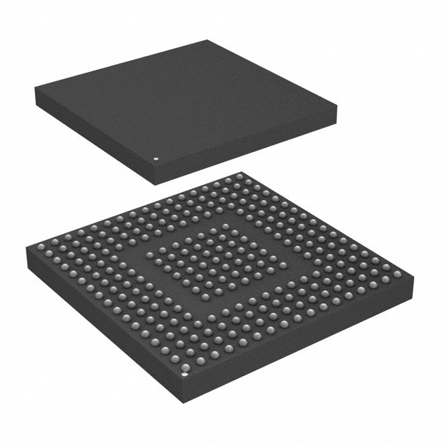
- Part No.:
- FS32R274VCK2MMM
- Manufacturer:
- NXP Semiconductors
- Category:
- Microcontrollers
- Package:
- 257-LFBGA
- Datasheet:
-
 FS32R274VCK2MMM.pdf
- Description:
- IC MCU 32BIT 2MB FLASH 257MAPBGA
- Quantity:
- Payment:

- Shipping:

Inventory:3,546
Please send an inquiry. Send us your inquiry, and we will respond immediately.
Product details
Overview
FS32R274VCK2MMM from NXP Semiconductors is a high-integrity radar microcontroller unit (Radar MCU) for automotive ADAS applications, featuring dual e200Z7 computation cores (200 MHz), one e200Z4 safety core (100 MHz), 2 MB ECC flash, 1.5 MB ECC SRAM, and integrated radar signal processing hardware including SPT, CTE, WGM, four 12-bit ΣΔ-ADCs (10 MSps), and one 12-bit DAC (10 MSps).
For engineers reviewing the FS32R274VCK2MMM datasheet, FS32R274VCK2MMM pinout, FS32R274VCK2MMM application, or FS32R274VCK2MMM equivalent, this page delivers verified functional safety architecture (ASIL-D capable), radar-specific timing and waveform generation capabilities, memory protection configuration, and real-world interface compatibility with MIPICSI2, FlexCAN-FD, FlexRay, and ENET MAC.
Technical Context
The FS32R274VCK2MMM implements a lock-step safety architecture with e200Z4 core and checker core, supported by FCCU, MEMU, STCU2, and EIM for ISO 26262 SEooC ASIL-D compliance. Its radar subsystem integrates Cross Timing Engine (CTE) for sub-nanosecond trigger synchronization and Waveform Generation Module (WGM) for chirp ramp control - both essential for FMCW radar timing precision.
Radar data path includes four independent 12-bit ΣΔ-ADC channels (10 MSps each), low-jitter PLL dedicated to ADC/DAC clocking, and MIPICSI2 Rx interface (4 lanes, 1 Gbps/lane) for external ADC connectivity. Memory subsystem uses end-to-end ECC across 2 MB flash and 1.5 MB SRAM, with SMPU and per-core MPU enforcing strict access isolation.
Key Specifications
| Parameter | Value and Actual Design Meaning |
|---|---|
| CPU Architecture | Power Architecture® e200Z4 (100 MHz, lock-step safety core) + dual e200Z7 (200 MHz, computation cores) |
| Flash Memory | 2 MB on-chip code flash with ECC and 64 KB EEPROM emulation - enables safe over-the-air updates and robust code storage |
| SRAM | 1.5 MB on-chip SRAM with ECC and 4-port/8-bank architecture - supports concurrent radar processing, safety monitoring, and communication tasks |
| ADC | 4× 12-bit ΣΔ-ADC at 10 MSps - provides high-resolution baseband sampling for multi-channel FMCW radar receivers |
| DAC | 1× 12-bit DAC at 10 MSps - generates precise chirp waveforms directly on-chip without external signal generators |
| Radar Acceleration | Signal Processing Toolbox (SPT), Cross Timing Engine (CTE), and Waveform Generation Module (WGM) - offloads FFT, timing sequencing, and chirp synthesis from CPU |
| Safety Certification | ISO 26262 SEooC ASIL-D compliant with FCCU, MEMU, safe eDMA, STCU2, and EIM - meets full automotive functional safety requirements |
| Interface Support | MIPICSI2 (4-lane Rx, 1 Gbps/lane), 3× FlexCAN (2 with CAN FD), dual-channel FlexRay (128 buffers), ENET MAC (MII/RMII/RGMII), Zipwire - enables sensor fusion and vehicle network integration |
Pinout & Package
FS32R274VCK2MMM is housed in a 257-pin MAPBGA package (15 mm × 15 mm, 0.8 mm pitch) with thermal pad, optimized for automotive radar EMI performance and thermal dissipation in front-end modules.
| Pin/Terminal | Circuit Role | Design Meaning |
|---|---|---|
| VDD_HV_IO | 3.3 V I/O supply | Power domain for GPIO, FlexCAN, LINFlexD, SPI, I²C, and PWM interfaces - requires local decoupling near package edge |
| VDD | 1.25 V core supply | Primary power for e200Z4/Z7 cores, SPT, CTE, and WGM - must be filtered with low-ESR ceramic capacitors |
| XOSC_IN / XOSC_OUT | 40 MHz crystal oscillator interface | Differential input for external 40 MHz crystal (ESR ≤30 Ω, 8 pF load) - critical for system clock stability and radar timing accuracy |
| SDADC0_P/N to SDADC3_P/N | ΣΔ-ADC analog inputs | Differential pairs for four independent radar receiver channels - routed as matched-length, shielded traces to preserve SNR |
| DAC_OUT | DAC analog output | Single-ended 12-bit output driving radar transmitter modulator - requires external reconstruction filter before RF upconversion |
| MIPICSI2_CLK / DATA0–3 | MIPICSI2 physical layer | 4-lane CSI-2 Rx interface supporting 1 Gbps/lane - connects to external high-speed ADCs for extended channel count |
| ETH_MDC / MDIO / TX/RX | ENET MAC interface | Supports MII/RMII/RGMII PHY connection - enables time-synchronized radar data streaming via IEEE 1588 PTP |
Key Features
| Feature | Design Value |
|---|---|
| Signal Processing Toolbox (SPT) | Hardware-accelerated FFT, CFAR, and beamforming - reduces CPU load by >70% during real-time radar point cloud generation |
| Cross Timing Engine (CTE) | Sub-1 ns jitter trigger distribution across ADCs, DAC, and WGM - ensures phase-coherent FMCW chirp transmission and reception |
| Waveform Generation Module (WGM) | Programmable chirp ramp generator with linear/non-linear profiles - eliminates need for external DDS or FPGA-based waveform synthesis |
| End-to-End ECC Protection | Full ECC coverage from CPU bus through crossbar, flash, SRAM, and peripheral registers - detects and corrects single-bit errors, reports double-bit faults |
| Functional Safety Subsystem | FCCU collects faults from all domains; MEMU handles memory errors; STCU2 manages BIST execution - enables certified ASIL-D runtime diagnostics |
| Cryptographic Security Engine (CSE2) | Hardware-accelerated AES-128/256, SHA-256, RSA-2048, and ECC - secures boot, firmware updates, and radar data confidentiality |
Applications
| Automotive Radar Front-End | ADAS Sensor Fusion Hub |
|---|---|
Use Scenario: 77 GHz FMCW radar transceiver module in corner radar or front long-range radar (LRR) units. IC Role / Device Role / Timing Role: Primary radar SoC managing chirp generation, ADC sampling, baseband processing, and CAN/FlexRay communication with host ECU. Use Value: Integrated WGM and CTE eliminate external timing ICs; SPT accelerates FFT processing to meet <100 μs latency for object detection. | Use Scenario: Centralized radar preprocessing node aggregating data from multiple radar sensors in L2+/L3 autonomous driving systems. IC Role / Device Role / Timing Role: Time-synchronized radar data concentrator using ENET MAC with IEEE 1588 PTP and FlexCAN-FD for deterministic inter-sensor coordination. Use Value: On-chip 1.5 MB ECC SRAM buffers multi-sensor point clouds; safe eDMA transfers data to host without CPU intervention. |
| Automotive Radar Calibration Platform | Industrial mmWave Sensing System |
Use Scenario: Production-line radar calibration fixture verifying chirp linearity, ADC gain matching, and timing skew across channels. IC Role / Device Role / Timing Role: Self-contained test controller generating known chirps via DAC, capturing responses via ΣΔ-ADCs, and computing calibration coefficients in real time. Use Value: Four synchronized ΣΔ-ADCs enable simultaneous multi-channel characterization; CTE ensures <50 ps inter-channel skew measurement capability. | Use Scenario: Industrial presence detection and material analysis system using 60 GHz mmWave sensing in factory automation or smart building applications. IC Role / Device Role / Timing Role: Standalone mmWave processor handling waveform generation, echo digitization, and Doppler/FFT analysis without host MCU dependency. Use Value: SPT and WGM support custom modulation schemes beyond automotive standards; -40°C to 125°C operation suits harsh industrial environments. |
Equivalent & Alternatives
The following parts are listed as comparable options for similar radar processing applications.
| Alternative Part | Technical Difference | Application Difference | Selection Advice |
|---|---|---|---|
| S32R274KCK2MMM | Higher-performance variant: e200Z7 cores at 240 MHz (vs. 200 MHz), e200Z4 at 120 MHz (vs. 100 MHz); same 2 MB flash, 1.5 MB SRAM, and radar peripherals | Targeted at premium LRR requiring higher FFT throughput and shorter chirp cycle times | Select S32R274KCK2MMM when system-level timing budget demands >20% faster SPT execution or tighter CTE jitter (<0.5 ns) |
| S32R264VCK0MMM | Removes ΣΔ-ADCs and DAC; replaces SDPLL with AFEPLL; no radar-specific analog front-end - retains e200Z7/Z4 cores, flash, SRAM, and digital interfaces | Intended for non-radar ADAS functions (e.g., camera preprocessor, gateway ECU) where radar acceleration is unnecessary | Choose S32R264VCK0MMM only if radar signal chain is fully external and system does not require on-chip chirp generation or ΣΔ-ADC sampling |
Compared with S32R274KCK2MMM, FS32R274VCK2MMM trades 20% lower CPU frequency for reduced power consumption and thermal footprint in space-constrained radar modules; compared with S32R264VCK0MMM, it uniquely delivers integrated radar analog front-end and timing infrastructure required for FMCW sensor autonomy.
Availability
FS32R274VCK2MMM is available at Aetrix Electronics and suitable for automotive radar front-end modules, ADAS sensor fusion hubs, radar calibration platforms, and industrial mmWave sensing systems requiring stable component supply, long-term lifecycle support, and ASIL-D compliance.
Supply support for FS32R274VCK2MMM includes scheduled delivery planning, volume procurement assistance, BOM continuity management, traceable sourcing, and lifecycle availability coordination for OEM customers, industrial embedded developers, connected-device designers, and electronics production programs.
Manufacturer
NXP Semiconductors is a global semiconductor company headquartered in Eindhoven, Netherlands, specializing in secure connectivity solutions for automotive, industrial, and IoT markets with leadership in radar, secure MCU, and wireless technologies.
The S32R274 series is part of NXP's S32 Automotive Platform, designed specifically for high-performance, safety-certified radar processing in ADAS and autonomous driving systems - integrating compute, timing, analog, and networking into a single ASIL-D-capable SoC.
FAQ
What is the maximum operating junction temperature for FS32R274VCK2MMM?
The FS32R274VCK2MMM has a maximum junction temperature (TJ) rating of 150°C, validated across its full operating voltage range and functional modes. This specification enables deployment in under-hood automotive radar modules where ambient temperatures exceed 105°C. Thermal design must ensure sustained TJ ≤150°C during worst-case radar processing loads, particularly when SPT, CTE, and ΣΔ-ADCs operate concurrently. The device includes two on-die temperature sensors (TSENS) for real-time thermal monitoring and throttling control.
Does FS32R274VCK2MMM support CAN FD, and which controllers enable it?
Yes, FS32R274VCK2MMM supports CAN FD on two of its three FlexCAN modules, as explicitly confirmed in the S32R274/S32R264 Series Data Sheet Rev. 6 (Section 1.2 and Table 1). The third FlexCAN module operates in classical CAN mode only. CAN FD capability enables data payloads up to 64 bytes and bit rates exceeding 5 Mbps - critical for high-bandwidth radar object lists and diagnostic streaming. Configuration is performed via MC_CGM and FlexCAN registers; no external transceivers are required beyond standard CAN FD PHYs.
How does the Cross Timing Engine (CTE) in FS32R274VCK2MMM improve radar timing accuracy?
The Cross Timing Engine (CTE) in FS32R274VCK2MMM delivers sub-nanosecond jitter trigger distribution to synchronize ΣΔ-ADC sampling, DAC output, WGM chirp events, and external peripherals. It achieves this through dedicated low-skew routing, on-die delay calibration, and hardware-triggered event chaining - eliminating software-induced latency and clock domain crossing uncertainty. In FS32R274VCK2MMM, CTE ensures inter-channel ADC sampling skew <50 ps and DAC-to-ADC phase alignment within ±100 ps, directly enabling coherent MIMO radar operation and high-fidelity Doppler estimation.
Is FS32R274VCK2MMM pin-compatible with other S32R274 variants such as FS32R274KCK2MMM?
Yes, FS32R274VCK2MMM is pin-compatible with all S32R274 variants in the 257MAPBGA package, including FS32R274KCK2MMM, FS32R274KSK2MMM, and FS32R274JSK2MMM. Pin mapping, power domains, I/O voltage levels, and peripheral signal assignments are identical across these variants. The differences lie solely in internal configuration (e.g., CPU clock frequencies, temperature grade, and flash programming options), allowing drop-in replacement during design iteration or production binning - provided PCB layout adheres to NXP's S32R274 layout guidelines for signal integrity and thermal management.
What debug interfaces does FS32R274VCK2MMM provide, and are they accessible during safety-critical operation?
FS32R274VCK2MMM provides a 4-pin JTAG interface and Nexus/Aurora Class 3+ debug port for high-speed tracing, both compliant with IEEE-ISTO 5001-2012. These interfaces remain accessible during functional operation but are disabled automatically upon entry into certain safety states (e.g., FCCU fault escalation or STCU2 BIST execution) to prevent interference with ASIL-D runtime integrity. Debug access requires explicit enablement via JTAGM module configuration and is subject to CSE2 security policies - ensuring trace visibility for development while preventing unauthorized runtime inspection in deployed systems.
FS32R274VCK2MMM Specifications
- Product attributes
- Attribute value
- Manufacturer:
- NXP Semiconductors
- Package/Case:
- 257-LFBGA
- Series:
- S32R
- Packaging:
- Tray
- Product Status:
- Active
- Programmable:
- Not Verified
- Core Processor:
- e200z4, e200z7 (2)
- Core Size:
- 32-Bit Tri-Core
- Speed:
- 180MHz, 240MHz
- Connectivity:
- CANbus, Ethernet, FlexRay, I2C, LINbus, SPI, ZipWire
- Peripherals:
- POR, PWM, WDT
- Number of I/O:
- -
- Program Memory Size:
- 2MB (2M x 8)
- Program Memory Type:
- FLASH
- EEPROM Size:
- 64K x 8
- RAM Size:
- 1.5M x 8
- Voltage - Supply (Vcc/Vdd):
- 1.19V ~ 5.5V
- Data Converters:
- A/D 16x12b SAR, 4x12 Sigma; D/A 1x12b
- Oscillator Type:
- Internal
- Operating Temperature:
- -40°C ~ 125°C (TA)
- Grade:
- -
- Qualification:
- -
- Mounting Type:
- Surface Mount
- Supplier Device Package:
FS32R274VCK2MMM FAQ
1.How can I place an order for FS32R274VCK2MMM through Aetrix?
Please submit a Request for Quotation (RFQ) for FS32R274VCK2MMM on Aetrix. Our sales agent will provide a competitive quotation and guide you through the order confirmation once you accept the terms.
2.Are the price and stock information for FS32R274VCK2MMM reliable?
The price and inventory of FS32R274VCK2MMM are updated periodically and may fluctuate due to market conditions. Stock and pricing data are typically refreshed every 24 hours. Quotation validity for FS32R274VCK2MMM is usually 5 days.
3.What payment methods are accepted for FS32R274VCK2MMM?
We accept Wire Transfer, PayPal, Credit Card, Western Union, MoneyGram, and Escrow for FS32R274VCK2MMM transactions.
Note: Certain payment methods may incur a processing fee.
4.How is shipping managed for FS32R274VCK2MMM?
FS32R274VCK2MMM orders can be shipped via leading logistics carriers, including DHL, UPS, FedEx, TNT, or Registered Mail.
Once your FS32R274VCK2MMM order is processed, you will receive an email with the shipment details and tracking number.
Note: Tracking information may take up to 24 hours to appear. Express delivery typically takes 3–5 business days.
5.How can I obtain technical support or documentation for FS32R274VCK2MMM?
For technical support, including FS32R274VCK2MMM datasheets, pinout diagrams, or application guidance, please contact our engineering support team. They can provide detailed documentation and assistance for your FS32R274VCK2MMM requirements.
6.How does Aetrix verify that FS32R274VCK2MMM is sourced from the original manufacturer or authorized distributors?
All FS32R274VCK2MMM products on Aetrix are procured from qualified distributors and authorized channels. Our dedicated quality assurance team conducts strict verification, including traceability checks and, if necessary, third-party testing. This ensures that FS32R274VCK2MMM meets industry standards.
7.What is the process for return or replacement of FS32R274VCK2MMM?
All FS32R274VCK2MMM units undergo pre-shipment inspection (PSI). If there is an issue with FS32R274VCK2MMM, returns or replacements are accepted under the following conditions:
1.Quantity discrepancies, incorrect items, or visible external defects (such as breakage or corrosion), acknowledged by Aetrix.
2.The issue is reported within 90 days of delivery.
3.The FS32R274VCK2MMM part is unused and in its original packaging.
Return procedure for FS32R274VCK2MMM:
1.Submit a request within 90 days.
2.Obtain a Return Material Authorization (RMA) from Aetrix.
FS32R274VCK2MMM Tags

-
ATTINY4-TSHR
Microchip Technology
-
ATTINY10-TSHR
Microchip Technology
-
ATTINY10-TS8R
Microchip Technology

-
ATTINY202-SSNR
Microchip Technology
-
ATTINY202-SSFR
Microchip Technology
-
ATTINY402-SSNR
Microchip Technology

-
PIC16F15213T-I/MF
Microchip Technology
-
PIC16F15213-E/MF
Microchip Technology

-
PIC10F200T-I/OT
Microchip Technology
-
ATTINY412-SSNR
Microchip Technology
-
PIC10F202T-I/OT
Microchip Technology

-
ATTINY404-SSNR
Microchip Technology
Tech Hub

A practical engineering guide to 3.3V and 5V logic compatibility, input thresholds, resistor dividers, translator ICs, MOSFET level shifting, I2C pull-ups, timing limits and power-sequencing risks.

The 74HC595 uses push-pull logic outputs, while the TPIC6B595 uses 50 V open-drain DMOS sinks for higher-power loads. This guide compares timing, current limits, 3.3 V interfacing, load wiring, thermal…

The 74HC595 converts serial data into eight stable parallel outputs. This guide covers pin functions, shift and storage timing, OE and MR behavior, drive-current limits, cascading, voltage compatibilit…

A technical comparison of level-sensitive latches and edge-triggered flip-flops, covering timing windows, setup and hold limits, master–slave operation, time borrowing, race-through, HDL inference and…

A D latch stores one bit while Enable controls when data can pass. This reference covers gate-level operation, truth tables, transparency, setup and hold timing, LE versus OE, common ICs and practical …

An SR latch stores one bit through cross-coupled feedback. This engineering reference covers NOR and NAND implementations, truth tables, forbidden-state recovery, gated operation, switch debouncing, fa…

Latch circuits retain one bit through feedback. This technical reference covers SR and D latches, truth tables, transparency, timing limits, latch-versus-flip-flop behavior, applications and common log…

An engineering guide to LED driver operation, constant-current and constant-voltage outputs, linear and switching topologies, dimming, IC selection, calculations, replacement compatibility, and fault c…

Operational amplifier guide covering op amp basics, feedback, ideal vs real op amps, common configurations, buffer circuits, offset, bias current, gain-bandwidth, slew rate, rail-to-rail limits and sel…

Jumper cables guide covering safe connection order, red and black clamp placement, final ground connection, cable gauge, length, clamp quality, copper vs CCA cables, jump starter comparison and battery…


