
 My Inquiry
 My Account


STMicroelectronics GS-R24F0002.0
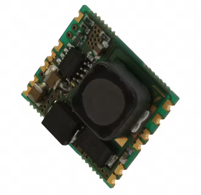
- Part No.:
- GS-R24F0002.0
- Manufacturer:
- STMicroelectronics
- Category:
- DC DC Converters
- Package:
- 12-SMD Module
- Datasheet:
-
 GS-R24F0002.0.pdf
- Description:
- DC DC CONVERTER 1.235-5.5V
- Quantity:
- Payment:

- Shipping:

Inventory:409
Please send an inquiry. Send us your inquiry, and we will respond immediately.
Product details
Overview
GS-R24F0002.0 from STMicroelectronics is a 2 A, non-isolated synchronous step-down DC-DC converter module with adjustable output voltage (1.235 V to 5.5 V), 16–35 V input range, 25 mVpp output ripple, and integrated thermal shutdown, remote inhibit, and synchronization capability - used in telecom power supplies and industrial distributed power systems.
For engineers reviewing the GS-R24F0002.0 datasheet, GS-R24F0002.0 pinout, GS-R24F0002.0 application, or GS-R24F0002.0 equivalent, key selection criteria include programmable feedback voltage (1.235 V), 225–275 kHz switching frequency, ±4% output accuracy, no-heatsink operation, and compatibility with multi-unit synchronization for noise-sensitive board-level power designs.
Technical Context
This module implements a fixed-frequency current-mode PWM controller based on the ST L5973 IC, delivering regulated output via external FB resistor programming. It features pulse-by-pulse overcurrent protection combined with frequency foldback during sustained overload.
Thermal shutdown activates at ≥150 °C with ~20 °C hysteresis; remote inhibit (INH) disables operation with <0.8 V (enable) or >2.2 V (disable), drawing ≤150 µA standby current at 35 V input. Synchronization is achieved by connecting Sync pins across multiple units.
Key Specifications
| Parameter | Value and Actual Design Meaning |
|---|---|
| Output current | 2 A max continuous; supports full load without heatsink up to 85 °C ambient |
| Input voltage range | 16–35 V DC; withstands 36 V absolute max, suitable for 24 V nominal industrial bus rails |
| Output voltage range | 1.235–5.5 V adjustable via external resistor on FB pin; 1.235 V is internal reference threshold |
| Switching frequency | 225–275 kHz typical; enables compact magnetics and avoids AM radio band interference |
| Output ripple | 25 mVpp at 24 V input / 2 A load; meets low-noise analog supply requirements |
| Efficiency range | 68–85% depending on VOUT; peaks near 5 V output under full load |
| Thermal shutdown | Activates at ≥150 °C junction temperature with 20 °C hysteresis to prevent oscillation |
Pinout & Package
GS-R24F0002.0 uses a 12-pin through-hole module package with dual input/output power terminals and dedicated control pins. Mechanical footprint matches standard 24 V DC-DC module layouts per Figure 6 in datasheet Rev 2.
| Pin/Terminal | Circuit Role | Design Meaning |
|---|---|---|
| 1 INH | Logic inhibit input | High (>2.2 V) disables regulator; internal pull-up ensures safe default-off state when floating |
| 2 Vref | 3.3 V reference output | Stable 3.3 V source for external circuitry; no capacitor required for stability |
| 3,4 Input+ | Positive DC input | Dual terminals reduce trace resistance and improve current sharing for 2 A operation |
| 5,6 Input GND | Input return path | Dedicated low-inductance ground returns minimize input loop area and EMI |
| 7,8 Output GND | Output return path | Separate output ground improves regulation accuracy and reduces ground bounce |
| 9,10 Vout | Regulated output | Dual terminals support high-current delivery and reduce voltage drop under load |
| 11 FB | Feedback input | Connects to resistor divider for output adjustment; senses 1.235 V reference internally |
| 12 Sync | Synchronization input/output | Enables master-slave frequency alignment across multiple modules to suppress beat frequencies |
Key Features
| Feature | Design Value |
|---|---|
| Remote logic inhibit | Reduces quiescent current to ≤150 µA at 35 V input, enabling low-power system sleep modes |
| Programmable output | Adjusts from 1.235 V to 5.5 V using single external resistor on FB pin - no DAC or digital interface needed |
| Multi-unit synchronization | Eliminates beat frequencies and reduces EMI in parallel configurations by aligning switching edges |
| Non-latching protection | Recovery after overload/short-circuit without manual reset; combines pulse-by-pulse current limit and frequency foldback |
| Thermal shutdown with hysteresis | Shuts down at ≥150 °C and restarts only after cooling to ~130 °C, preventing thermal cycling damage |
Applications
| Telecom Power Shelf | Industrial PLC I/O Module |
|---|---|
Use Scenario: Provides isolated 3.3 V or 5 V rail for FPGA configuration, Ethernet PHY, and microcontroller logic in 19-inch rack-mounted telecom equipment. IC Role / Device Role / Timing Role: Primary point-of-load regulator converting 24 V backplane to stable low-voltage logic supply. Use Value: 25 mVpp ripple and 225–275 kHz switching enable clean digital timing margins without additional LC filtering. |
Use Scenario: Powers analog sensor front-ends, ADC references, and isolated CAN transceivers in modular industrial controllers operating in harsh environments. IC Role / Device Role / Timing Role: Adjustable-output DC-DC stage delivering precise 1.8 V or 2.5 V to high-resolution data acquisition circuits. Use Value: Programmable 1.235 V reference and ±4% output accuracy ensure stable reference voltage for 16-bit ADC performance. |
| Embedded Computer Power | Distributed Power Architecture |
Use Scenario: Supplies core voltage to ARM-based SBCs in edge computing gateways where space and thermal constraints preclude discrete buck solutions. IC Role / Device Role / Timing Role: Compact, self-contained step-down module replacing linear regulators and external MOSFET drivers. Use Value: No heatsink required and -25 °C to +85 °C operation support fanless enclosure designs in wide-temperature deployments. |
Use Scenario: Used in multi-rail power systems where several GS-R24F modules generate different voltages (e.g., 1.2 V, 3.3 V, 5 V) from a common 24 V bus. IC Role / Device Role / Timing Role: Synchronized buck module ensuring coherent switching across rails to simplify EMI filter design. Use Value: Pin-strapped Sync functionality eliminates inter-rail beat frequencies, reducing conducted emissions by up to 10 dBµV. |
Equivalent & Alternatives
The following parts are listed as comparable options for similar adjustable-output DC-DC converter applications.
| Alternative Part | Technical Difference | Application Difference | Selection Advice |
|---|---|---|---|
| LMZ12002TZX | 2 A, 4.5–20 V input, fixed 3.3/5 V or adjustable 0.8–6 V; integrated inductor; 12-pin QFN | Surface-mount only; lacks Sync and INH pins; higher quiescent current (5 mA vs. 150 µA) | Prefer for space-constrained PCBs where thermal management allows QFN mounting and synchronization is not required. |
| TPS54227 | 2 A, 4.5–18 V input, adjustable 0.76–15.5 V; external FETs; 8-pin SOIC | Requires external MOSFETs, inductor, and compensation components; lower integration level | Choose when design flexibility (e.g., custom inductor selection or higher efficiency tuning) outweighs BOM count and layout complexity. |
Compared with LMZ12002TZX and TPS54227, GS-R24F0002.0 offers through-hole robustness, built-in Sync/INH logic, ultra-low standby current, and no external power-stage components - making it optimal for industrial retrofit, telecom legacy board upgrades, and noise-sensitive multi-module systems.
Availability
GS-R24F0002.0 is available at Aetrix Electronics and suitable for telecom power shelves, industrial PLC I/O modules, and embedded computer power supplies requiring stable component supply, long-life availability, and proven field reliability.
Supply support for GS-R24F0002.0 includes scheduled delivery planning, volume procurement assistance, BOM continuity management, traceable sourcing, and lifecycle availability coordination for OEM customers, industrial embedded developers, connected-device designers, and electronics production programs.
Manufacturer
STMicroelectronics is a global semiconductor leader headquartered in Geneva, Switzerland, designing and manufacturing microcontrollers, power management ICs, sensors, and analog devices for industrial, automotive, and consumer markets.
GS-R24F belongs to ST's high-reliability DC-DC module product line, engineered specifically for industrial and telecom applications demanding rugged through-hole construction, extended temperature operation, and simplified system-level power design.
FAQ
What is the minimum output voltage achievable with GS-R24F0002.0?
The minimum output voltage is 1.235 V, which corresponds to the internal feedback reference voltage. This value is fixed and cannot be lowered further, even with zero-ohm resistor between FB and Vout. The device achieves regulation by comparing the FB node voltage to this 1.235 V threshold.
Can GS-R24F0002.0 operate with input voltage below 16 V?
No - the datasheet specifies 16 V as the absolute minimum input voltage for guaranteed operation. Below 16 V, the internal controller may fail to start or sustain regulation due to insufficient headroom for the internal bias circuitry and gate drive requirements of the integrated power stage.
How is synchronization implemented between multiple GS-R24F0002.0 units?
Synchronization is achieved by connecting all Sync pins (pin 12) together. The unit with the highest natural switching frequency automatically becomes the master; others lock to that frequency. No external clock source or configuration is required - the function is fully hardware-based and self-configuring.
Does GS-R24F0002.0 require external compensation components?
Not by default - the module is internally compensated for standard loads. However, for highly capacitive or dynamic loads, an external capacitor can be added between FB and Vout (as described in Section 4.8) to adjust loop phase margin and transient response, using the same physical location as the programming resistor.
GS-R24F0002.0 Specifications
- Product attributes
- Attribute value
- Manufacturer:
- STMicroelectronics
- Series:
- GS-R24F
- Package/Case:
- 12-SMD Module
- Packaging:
- Bulk
- Product Status:
- Obsolete
- Type:
- Non-Isolated PoL Module
- Number of Outputs:
- 1
- Voltage - Input (Min):
- 16V
- Voltage - Input (Max):
- 35V
- Voltage - Output 1:
- 1.235 ~ 5.5V
- Voltage - Output 2:
- -
- Voltage - Output 3:
- -
- Voltage - Output 4:
- -
- Current - Output (Max):
- 2A
- Power (Watts):
- -
- Voltage - Isolation:
- -
- Applications:
- ITE (Commercial)
- Features:
- Remote On/Off, OCP, OTP, OVP
- Operating Temperature:
- -25°C ~ 85°C
- Efficiency:
- 85%
- Grade:
- -
- Qualification:
- -
- Mounting Type:
- Surface Mount
- Supplier Device Package:
- -
- Control Features:
- -
- Approval Agency:
- -
- Standard Number:
- -
GS-R24F0002.0 FAQ
1.How can I place an order for GS-R24F0002.0 through Aetrix?
Please submit a Request for Quotation (RFQ) for GS-R24F0002.0 on Aetrix. Our sales agent will provide a competitive quotation and guide you through the order confirmation once you accept the terms.
2.Are the price and stock information for GS-R24F0002.0 reliable?
The price and inventory of GS-R24F0002.0 are updated periodically and may fluctuate due to market conditions. Stock and pricing data are typically refreshed every 24 hours. Quotation validity for GS-R24F0002.0 is usually 5 days.
3.What payment methods are accepted for GS-R24F0002.0?
We accept Wire Transfer, PayPal, Credit Card, Western Union, MoneyGram, and Escrow for GS-R24F0002.0 transactions.
Note: Certain payment methods may incur a processing fee.
4.How is shipping managed for GS-R24F0002.0?
GS-R24F0002.0 orders can be shipped via leading logistics carriers, including DHL, UPS, FedEx, TNT, or Registered Mail.
Once your GS-R24F0002.0 order is processed, you will receive an email with the shipment details and tracking number.
Note: Tracking information may take up to 24 hours to appear. Express delivery typically takes 3–5 business days.
5.How can I obtain technical support or documentation for GS-R24F0002.0?
For technical support, including GS-R24F0002.0 datasheets, pinout diagrams, or application guidance, please contact our engineering support team. They can provide detailed documentation and assistance for your GS-R24F0002.0 requirements.
6.How does Aetrix verify that GS-R24F0002.0 is sourced from the original manufacturer or authorized distributors?
All GS-R24F0002.0 products on Aetrix are procured from qualified distributors and authorized channels. Our dedicated quality assurance team conducts strict verification, including traceability checks and, if necessary, third-party testing. This ensures that GS-R24F0002.0 meets industry standards.
7.What is the process for return or replacement of GS-R24F0002.0?
All GS-R24F0002.0 units undergo pre-shipment inspection (PSI). If there is an issue with GS-R24F0002.0, returns or replacements are accepted under the following conditions:
1.Quantity discrepancies, incorrect items, or visible external defects (such as breakage or corrosion), acknowledged by Aetrix.
2.The issue is reported within 90 days of delivery.
3.The GS-R24F0002.0 part is unused and in its original packaging.
Return procedure for GS-R24F0002.0:
1.Submit a request within 90 days.
2.Obtain a Return Material Authorization (RMA) from Aetrix.
GS-R24F0002.0 Tags
-
1S4E_0505S1.5U
GAPTEC Electronic
-
TPS631000DRLR
Texas Instruments
-
XCL209F083DR
Torex Semiconductor Ltd
-
SC202AMLTRT
Semtech Corporation

-
NME1S0505SC
Murata Power Solutions Inc.
-
XCL101A501ER-G
Torex Semiconductor Ltd
-
RFM-0505S
Recom Power
-
TEA 1-0505E
Traco Power
-
MIC33153YHJ-TR
Microchip Technology
-
TEA 1-0505
Traco Power
-
TPSM863252RDXR
Texas Instruments
-
RFB-0505S
Recom Power
Tech Hub

A practical engineering and sourcing framework covering lifecycle verification, lifetime-buy calculations, replacement qualification, supplier checks and counterfeit-risk controls.

TTL and CMOS logic families differ in thresholds, loading, output drive, power and timing. This engineering guide compares 74HC and 74HCT, calculates noise margins and checks 3.3 V/5 V compatibility.

A practical engineering guide to 3.3V and 5V logic compatibility, input thresholds, resistor dividers, translator ICs, MOSFET level shifting, I2C pull-ups, timing limits and power-sequencing risks.

The 74HC595 uses push-pull logic outputs, while the TPIC6B595 uses 50 V open-drain DMOS sinks for higher-power loads. This guide compares timing, current limits, 3.3 V interfacing, load wiring, thermal…

The 74HC595 converts serial data into eight stable parallel outputs. This guide covers pin functions, shift and storage timing, OE and MR behavior, drive-current limits, cascading, voltage compatibilit…

A technical comparison of level-sensitive latches and edge-triggered flip-flops, covering timing windows, setup and hold limits, master–slave operation, time borrowing, race-through, HDL inference and…

A D latch stores one bit while Enable controls when data can pass. This reference covers gate-level operation, truth tables, transparency, setup and hold timing, LE versus OE, common ICs and practical …

An SR latch stores one bit through cross-coupled feedback. This engineering reference covers NOR and NAND implementations, truth tables, forbidden-state recovery, gated operation, switch debouncing, fa…

Latch circuits retain one bit through feedback. This technical reference covers SR and D latches, truth tables, transparency, timing limits, latch-versus-flip-flop behavior, applications and common log…

An engineering guide to LED driver operation, constant-current and constant-voltage outputs, linear and switching topologies, dimming, IC selection, calculations, replacement compatibility, and fault c…


