
 My Inquiry
 My Account


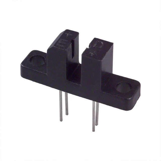
 H21A2.pdf


Inventory:4,037
Please send an inquiry. Send us your inquiry, and we will respond immediately.
Product details
Overview
H21A2 from Fairchild Semiconductor is a phototransistor-based optical interrupter switch comprising a GaAs infrared LED coupled to a silicon NPN phototransistor in a 4-pin DIP plastic housing with 0.125" (3.2 mm) pin spacing and 0.119" (3.0 mm) body width. It delivers 2.0 mA on-state collector current at IF = 20 mA, VCE = 5 V, with 8 µs turn-on and 50 µs turn-off times, and operates across –55°C to +100°C for position sensing in motor encoders.
For engineers reviewing the H21A2 datasheet, pinout, applications, or equivalent options, key selection criteria include guaranteed IC(ON) ≥2.0 mA at 20 mA input, VCEO = 30 V, saturation voltage ≤0.40 V, thermal derating of 1.33 mW/°C above 25°C, and mechanical gap dimensions optimized for opaque flag interruption.
Technical Context
The H21A2 implements a monolithic optocoupled interrupter architecture: an infrared emitter (IF max = 50 mA, VF typ = 1.7 V) optically aligned to a phototransistor detector (VCEO = 30 V, ICEO ≤100 nA) across a fixed air gap. Its switching behavior is governed by photon flux density and base-emitter junction sensitivity, not external biasing.
Electrical isolation is inherent-no galvanic connection exists between input and output sides. Timing performance (ton = 8 µs, toff = 50 µs) is specified under pulsed conditions (PW = 100 µs, PRR = 100 pps) with RL = 2.5 kΩ, and exhibits predictable temperature dependence per Figures 2–4 in DS300290.
Key Specifications
| Parameter | Value and Actual Design Meaning |
|---|---|
| IC(ON) | 2.0 mA minimum at IF = 20 mA, VCE = 5 V - guarantees reliable logic-level switching into standard TTL loads |
| VCEO | 30 V - supports operation with 5 V or 12 V collector supply rails while maintaining safe margin |
| ton / toff | 8 µs / 50 µs - enables detection of mechanical events up to ~10 kHz in encoder or limit-switch applications |
| Operating Temp | –55°C to +100°C - qualified for industrial motor control and automotive under-hood environments |
| Package | 4-pin DIP with 0.125" pin pitch and 0.119" body width - compatible with standard 0.1" grid PCB layouts and wave soldering |
| Isolation Voltage | Not specified in DS300290 - device is rated for functional isolation only, not safety-critical reinforced insulation |
| VF (Emitter) | 1.7 V typical at IF = 60 mA - determines series resistor value for 5 V drive (e.g., 165 Ω for 20 mA) |
Pinout & Package
Package: 4-pin dual-in-line plastic housing (DIP), 0.125" (3.2 mm) pin pitch, 0.119" (3.0 mm) body width, 0.422" (10.7 mm) length, with molded optical gap. Pin 1 marked by dot or chamfered corner.
| Pin/Terminal | Circuit Role | Design Meaning |
|---|---|---|
| PIN 1 | Anode | Connects to positive supply through current-limiting resistor for IR LED forward bias |
| PIN 2 | Cathode | LED return path; ties to ground or driver low-side switch |
| PIN 3 | Collector | Phototransistor output node; pulled high via load resistor to enable active-low switching |
| PIN 4 | Emiter | Phototransistor emitter; typically grounded to complete output circuit |
Key Features
| Feature | Design Value |
|---|---|
| Optical coupling efficiency | H21A2 guarantees IC(ON) ≥2.0 mA at IF = 20 mA - higher than H21A1 (0.15×), enabling lower drive current and reduced power dissipation |
| Mechanical gap design | Fixed aperture geometry with .035" openings and opaque housing - rejects ambient light and ensures repeatable flag-interrupt threshold |
| Thermal derating | Linear 1.33 mW/°C reduction in PD above 25°C - allows accurate power budgeting in enclosed encoders or hot-running cabinets |
| Soldering compatibility | Rated for 240°C iron (5 s) and 260°C flow (10 s) - supports both manual rework and automated assembly without lens or bond-wire damage |
| Low-cost plastic DIP | No metal can or hermetic seal - reduces BOM cost while maintaining reliability in non-military industrial use cases |
Applications
| Motor Encoder Position Sensing | Printer Paper Jam Detection |
|---|---|
|
Use Scenario: Detecting slotted disk rotation in DC brushless motor feedback loops. IC Role / Device Role / Timing Role: Optical interrupter providing digital edge pulses synchronized to rotor position. Use Value: 8 µs turn-on time ensures <1% timing error at 10 kHz encoder resolution; 2.0 mA IC(ON) drives Schmitt-trigger inputs directly. |
Use Scenario: Monitoring paper path continuity in inkjet printer feed mechanisms. IC Role / Device Role / Timing Role: Flag-interrupt sensor confirming paper presence or stall condition. Use Value: Opaque housing and fixed gap reject ambient light in office environments; –55°C to +100°C rating covers thermal cycling during warm-up and duty cycles. |
| Industrial Limit Switch Replacement | Conveyor Belt Object Counting |
|
Use Scenario: Replacing mechanical microswitches in CNC machine tool end-stop detection. IC Role / Device Role / Timing Role: Solid-state position switch eliminating contact wear and bounce. Use Value: 50 µs turn-off time prevents double-counting during rapid actuation; 30 V VCEO withstands 24 V PLC interface voltages. |
Use Scenario: Counting discrete items passing through a production line gate. IC Role / Device Role / Timing Role: Edge-triggered object detector using opaque vane interruption. Use Value: Guaranteed IC(ON) ≥2.0 mA ensures noise margin against EMI in factory-floor wiring; DIP package simplifies mounting on modular sensor brackets. |
Equivalent & Alternatives
The following parts are listed as comparable options for similar optical interrupter applications.
| Alternative Part | Technical Difference | Application Difference | Selection Advice |
|---|---|---|---|
| HCPL-2630 | Higher speed (ton = 2 µs, toff = 2 µs), SOIC-4 package, 5 kV isolation rating | Designed for isolated logic-level signal transmission, not mechanical flag interruption | Choose HCPL-2630 only when galvanic isolation and sub-µs timing are required; not drop-in for H21A2's DIP gap-mounting |
| EE-SX1071 | Slot width 3.0 mm vs. H21A2's ~2.8 mm; IC(ON) = 0.5 mA min at IF = 20 mA; TO-5 metal-can package | Optimized for high-reliability industrial sensors with metal shielding; lower output current | Choose EE-SX1071 where EMI immunity and long-term stability outweigh cost and board space; requires different mounting hardware |
Compared with HCPL-2630 and EE-SX1071, the H21A2 offers the best balance of cost, DIP mountability, and guaranteed 2.0 mA output for direct TTL interfacing-making it optimal for high-volume motor encoder and paper-path detection where moderate speed suffices.
Availability
H21A2 is available at Aetrix Electronics and suitable for motor encoder position sensing, printer paper jam detection, industrial limit switch replacement, and conveyor belt object counting requiring stable component supply and consistent optical interrupter performance across temperature extremes.
Supply support for H21A2 includes scheduled delivery planning, volume procurement assistance, BOM continuity management, traceable sourcing, and lifecycle availability coordination for OEM customers, industrial embedded developers, connected-device designers, and electronics production programs.
Manufacturer
Fairchild Semiconductor was a U.S.-based analog and power semiconductor manufacturer acquired by ON Semiconductor in 2016; known for high-volume optoelectronics and power management ICs.
The H21A2 belongs to Fairchild's legacy optical interrupter family designed specifically for cost-sensitive, mechanically robust position and presence sensing in industrial automation and office equipment.
FAQ
What is the guaranteed minimum on-state collector current for H21A2?
The H21A2 guarantees IC(ON) ≥2.0 mA when driven with IF = 20 mA and biased at VCE = 5 V, as specified in the Electrical/Optical Characteristics table of DS300290. This value is measured under pulsed conditions (PW = 100 µs, PRR = 100 pps) and ensures reliable switching into standard logic inputs. The H21A2 datasheet confirms this parameter applies exclusively to the H21A2 variant-not H21A1 or H21A3.
Can H21A2 be used in place of H21A1 or H21A3?
No-H21A2 is not interchangeable with H21A1 or H21A3 due to differing optical coupling gains: H21A1 specifies IC(ON) ≥0.15 mA, H21A2 ≥2.0 mA, and H21A3 ≥4.0 mA at identical test conditions. Substituting H21A2 for H21A1 may overload downstream circuitry; using H21A1 instead of H21A2 risks insufficient output current. Each H21A2 variant must be selected based on required output drive strength.
What is the maximum continuous forward current rating for the H21A2 emitter?
The H21A2 emitter has a maximum continuous forward current (IF) rating of 50 mA, as stated in the Absolute Maximum Ratings table. Exceeding this value risks LED degradation or catastrophic failure. For reliable 20 mA operation-the condition under which IC(ON) is specified-a series resistor of ~165 Ω is recommended with a 5 V supply, accounting for VF ≈ 1.7 V. Derating applies above 25°C ambient.
Does H21A2 provide electrical isolation between input and output?
Yes, the H21A2 provides functional electrical isolation via optical coupling: the infrared LED (pins 1–2) and phototransistor (pins 3–4) share no conductive path. However, DS300290 does not specify isolation voltage rating (e.g., 5 kV), creepage, or clearance-so H21A2 is unsuitable for safety-critical isolation. It is intended for noise rejection and level-shifting, not regulatory-compliant galvanic separation.
What are the recommended soldering conditions for H21A2?
H21A2 is rated for hand soldering at 240°C for 5 seconds and flow soldering at 260°C for 10 seconds, per Note 2 in DS300290. RMA flux and methanol/isopropyl alcohol cleaning are recommended. Soldering iron tip must stay ≥1/16" (1.6 mm) from the housing to avoid lens distortion or internal bond damage. These limits ensure integrity of the epoxy lens and die attach without compromising optical alignment.
H21A2 Specifications
- Product attributes
- Attribute value
- Manufacturer:
- onsemi
- Series:
- -
- Package/Case:
- Slotted, PC Pins
- Packaging:
- Tube
- Product Status:
- Obsolete
- Sensing Distance:
- 0.118" (3mm)
- Sensing Method:
- Through-Beam
- Output Configuration:
- Phototransistor
- Current - DC Forward (If) (Max):
- 50 mA
- Current - Collector (Ic) (Max):
- 20 mA
- Voltage - Collector Emitter Breakdown (Max):
- 30 V
- Response Time:
- 8µs, 150µs
- Operating Temperature:
- -55°C ~ 100°C
- Grade:
- -
- Qualification:
- -
- Mounting Type:
- Through Hole, Flange
H21A2 FAQ
1.How can I place an order for H21A2 through Aetrix?
Please submit a Request for Quotation (RFQ) for H21A2 on Aetrix. Our sales agent will provide a competitive quotation and guide you through the order confirmation once you accept the terms.
2.Are the price and stock information for H21A2 reliable?
The price and inventory of H21A2 are updated periodically and may fluctuate due to market conditions. Stock and pricing data are typically refreshed every 24 hours. Quotation validity for H21A2 is usually 5 days.
3.What payment methods are accepted for H21A2?
We accept Wire Transfer, PayPal, Credit Card, Western Union, MoneyGram, and Escrow for H21A2 transactions.
Note: Certain payment methods may incur a processing fee.
4.How is shipping managed for H21A2?
H21A2 orders can be shipped via leading logistics carriers, including DHL, UPS, FedEx, TNT, or Registered Mail.
Once your H21A2 order is processed, you will receive an email with the shipment details and tracking number.
Note: Tracking information may take up to 24 hours to appear. Express delivery typically takes 3–5 business days.
5.How can I obtain technical support or documentation for H21A2?
For technical support, including H21A2 datasheets, pinout diagrams, or application guidance, please contact our engineering support team. They can provide detailed documentation and assistance for your H21A2 requirements.
6.How does Aetrix verify that H21A2 is sourced from the original manufacturer or authorized distributors?
All H21A2 products on Aetrix are procured from qualified distributors and authorized channels. Our dedicated quality assurance team conducts strict verification, including traceability checks and, if necessary, third-party testing. This ensures that H21A2 meets industry standards.
7.What is the process for return or replacement of H21A2?
All H21A2 units undergo pre-shipment inspection (PSI). If there is an issue with H21A2, returns or replacements are accepted under the following conditions:
1.Quantity discrepancies, incorrect items, or visible external defects (such as breakage or corrosion), acknowledged by Aetrix.
2.The issue is reported within 90 days of delivery.
3.The H21A2 part is unused and in its original packaging.
Return procedure for H21A2:
1.Submit a request within 90 days.
2.Obtain a Return Material Authorization (RMA) from Aetrix.
H21A2 Tags
-
GP1S094HCZ0F
SHARP/Socle Technology
-
GP1S092HCPIF
SHARP/Socle Technology
-
GP1S396HCPSF
SHARP/Socle Technology
-
LTH-301-07
Lite-On Inc.
-
RPI-352
Rohm Semiconductor
-
RPI-0226
Rohm Semiconductor
-
TCPT1300X01
Vishay Semiconductor Opto Division
-
EE-SX1320
Omron Electronics Inc-EMC Div

-
TCUT1300X01
Vishay Semiconductor Opto Division
-
EE-SX1103
Omron Electronics Inc-EMC Div

-
H22A1
Isocom Components 2004 LTD
-
EE-SX1041
Omron Electronics Inc-EMC Div
Tech Hub

Counterfeit components can hide behind convincing markings and passing basic function tests. This engineering reference covers source traceability, external inspection, X-ray, XRF, electrical testing, …

A practical engineering and sourcing framework covering lifecycle verification, lifetime-buy calculations, replacement qualification, supplier checks and counterfeit-risk controls.

TTL and CMOS logic families differ in thresholds, loading, output drive, power and timing. This engineering guide compares 74HC and 74HCT, calculates noise margins and checks 3.3 V/5 V compatibility.

A practical engineering guide to 3.3V and 5V logic compatibility, input thresholds, resistor dividers, translator ICs, MOSFET level shifting, I2C pull-ups, timing limits and power-sequencing risks.

The 74HC595 uses push-pull logic outputs, while the TPIC6B595 uses 50 V open-drain DMOS sinks for higher-power loads. This guide compares timing, current limits, 3.3 V interfacing, load wiring, thermal…

The 74HC595 converts serial data into eight stable parallel outputs. This guide covers pin functions, shift and storage timing, OE and MR behavior, drive-current limits, cascading, voltage compatibilit…

A technical comparison of level-sensitive latches and edge-triggered flip-flops, covering timing windows, setup and hold limits, master–slave operation, time borrowing, race-through, HDL inference and…

A D latch stores one bit while Enable controls when data can pass. This reference covers gate-level operation, truth tables, transparency, setup and hold timing, LE versus OE, common ICs and practical …

An SR latch stores one bit through cross-coupled feedback. This engineering reference covers NOR and NAND implementations, truth tables, forbidden-state recovery, gated operation, switch debouncing, fa…

Latch circuits retain one bit through feedback. This technical reference covers SR and D latches, truth tables, transparency, timing limits, latch-versus-flip-flop behavior, applications and common log…


