
 My Inquiry
 My Account


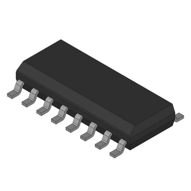
Renesas HA12181FP-EL-E
- Part No.:
- HA12181FP-EL-E
- Manufacturer:
- Renesas
- Category:
- DSP (Digital Signal Processors)
- Package:
- -
- Datasheet:
-
 HA12181FP-EL-E.pdf
- Description:
- AM RADIO NOISE REDUCTION SYSTEM
- Quantity:
- Payment:

- Shipping:

Inventory:2,000
Please send an inquiry. Send us your inquiry, and we will respond immediately.
Product details
Overview
HA12181FP-EL-E from Renesas Technology Corp. is a dedicated AM radio noise reduction IC integrating IF amplifier, detector, audio amplifier, AGC, linear waveform compensation circuit, and dual gate pulse generator for impulse noise suppression. It delivers 46 dB typical noise suppression, –0.5 dB typical gain loss, 0.06% THD, and operates from 7.0–10.0 V supply - used in analog AM broadcast receivers to eliminate crackle and pop artifacts.
For engineers reviewing the HA12181FP-EL-E datasheet, HA12181FP-EL-E pinout, HA12181FP-EL-E application, or HA12181FP-EL-E equivalent, key selection criteria include verified noise suppression ratio (NSR), AF output voltage stability across VCC (7–10 V), THD performance at 100 mVrms input, external capacitor tolerance requirements (±5% for C509–C512), and gate pulse timing control via R503/C507.
Technical Context
The HA12181FP-EL-E implements a dual-path noise detection architecture: one path samples IF signal pre-narrowband filtering (Point B in system diagram) to detect impulse width; the other processes the delayed AF signal to generate linear approximation of noise transients. Its stabilized current circuit enables precise waveform compensation using C509–C512 with matched ±5% tolerance.
It integrates two independent gate pulse detectors (Pulse Det.(1) and Pulse Det.(2)) driving separate gate pulse generators for adaptive noise blanking, with sensitivity set by R502 (22 kΩ typical) at Pin 12 and timing controlled by R503 (180 kΩ) and C507 (2200 pF) at Pin 11. The phase circuit (Pin 5, C512 = 0.068 µF) and hold capacitor (Pin 6, C511 = 0.033 µF) enable voltage-difference capture for linear reconstruction.
Key Specifications
| Parameter | Value and Actual Design Meaning |
|---|---|
| Noise Suppression Ratio | 46 dB typ. - measurable reduction of impulse noise amplitude in recovered AF output under defined test waveform (2 ms pulse, 100 mV, 10 µs rise) |
| Supply Voltage Range | 7.0 V to 10.0 V - supports standard AM radio power rails; 8.2 V typical operation point with stable ICC = 11.0 mA |
| Total Harmonic Distortion | 0.06% typ. at 100 mVrms, 1 kHz - ensures high-fidelity audio recovery without added distortion during noise cancellation |
| Signal-to-Noise Ratio | 75 dB typ. (AF input), 45 dB typ. (IF input) - confirms low internal noise floor and effective separation of signal from residual noise post-processing |
| Output Voltage | 78 mVrms typ. recovered AF output (Pin 9) with IF input - matches standard line-level interface requirements for downstream audio stages |
| Operating Temperature | –40°C to +85°C - qualified for consumer and automotive cabin-ambient environments without derating |
| Package | FP-16DA (SC-530-16C) - 16-pin plastic SIP package with 2.2 mm max height, 10.06 mm length, 5.5 mm width, 0.24 g weight |
Pinout & Package
HA12181FP-EL-E uses the FP-16DA (SC-530-16C) 16-pin single-in-line plastic package with 2.54 mm pin pitch, 0.42 mm lead thickness, and 0.22 mm lead width. Pin 7 is ground reference; Pins 13 and 16 are power and IF input respectively; all analog signal pins (3, 9, 14, 15) require tight capacitor tolerance (±5% for C509–C512) for waveform fidelity.
| Pin/Terminal | Circuit Role | Design Meaning |
|---|---|---|
| 1 | IF AGC Time Constant | RC network (R500/C502) sets AGC loop response; 100 kΩ/3.3 µF yields stable IF AGC settling without overshoot |
| 2 | Bias1 Bypass | Stabilizes internal voltage regulator; 0.033 µF bypass (C500) prevents noise injection into bias rail |
| 3 | AF Input | Differential-capable audio input node; DC bias ~3.3 V; requires 1 µF AC coupling (C513) for signal integrity |
| 4 | Bias2 Filter Current Set | Sets cutoff frequency of HPF/LPF networks; 12 kΩ (R506) defines filter corner; deviation shifts passband |
| 5 | Phase Circuit | Feeds phase-shifted signal to waveform compensation block; 0.068 µF (C512) must match C510 ±5% for linear approximation accuracy |
| 6 | Hold Capacitor Node | Stores differential voltage (VA–VB) during noise event; 0.033 µF (C511) must be exact value to avoid waveform step error |
| 7 | GND | Analog ground reference for all internal circuits; requires low-impedance PCB connection to minimize noise coupling |
| 8 | High-Pass Amp (Comp) | Waveform compensation path input; 0.033 µF (C510) matches C509 to maintain flat frequency response in normal mode |
| 9 | AF Output | Buffered audio output; 78 mVrms typical into 16 Ω load; 1 µF (C508) blocks DC; R504 = 4.7 kΩ sets output impedance |
| 10 | Waveform Compensation | Feedback node for linear approximation; 0.033 µF (C509) must equal C511 ±5% to prevent slope error in reconstructed waveform |
| 11 | Gate Pulse Generator (1) | Drives first blanking switch; pulse width set by R503 (180 kΩ)/C507 (2200 pF); wider values increase blanking duration |
| 12 | Noise Detection Threshold | Sets sensitivity of noise detector; 22 kΩ (R502) yields 1.1 V threshold; lower resistance increases false-trigger risk |
| 13 | VCC | Main supply input; 8.2 V typical; absolute max 16 V; decoupling via C506 (100 µF) required for ripple suppression |
| 14 | IF Detector Output | AGC detector output; 3.3 V DC level; 0.01 µF (C503) filters high-frequency ripple from IF demodulation |
| 15 | AF AGC Time Constant | RC network (R505/C504) controls AF AGC loop; 47 kΩ/0.22 µF provides smooth gain adaptation during signal fades |
| 16 | IF Input | High-impedance IF signal input; 1.3 V DC bias; 1000 pF (C501) couples 450 kHz IF signal while blocking DC offset |
Key Features
| Feature | Design Value |
|---|---|
| Dual gate pulse generation | Enables independent blanking of leading and trailing edges of impulse noise via Pins 11 and internal Pulse Det.(2) |
| Linear waveform approximation | Uses stabilized current source and matched capacitors (C509/C511/C512) to reconstruct noise-free AF signal segment |
| Integrated IF/AF AGC loops | Separate time constants (Pin 1/15) allow optimized dynamic range control for IF carrier and recovered audio |
| Low external component count | Requires only 12 passive components (8 caps, 4 resistors) for full noise cancellation function - no inductors or trimmers |
| Matched capacitor tolerance requirement | C509, C510, C511, C512 must be ±5% to ensure <1% slope error in linear approximation and <0.5 dB gain deviation |
Applications
| AM Broadcast Receiver | Car Radio Audio Front-End |
|---|---|
Use Scenario: Analog AM tuner in portable or desktop radios receiving terrestrial broadcast signals with atmospheric or ignition noise. IC Role / Device Role / Timing Role: Primary noise cancellation engine performing real-time impulse detection, waveform linearization, and gated blanking before audio amplification. Use Value: Delivers 46 dB noise suppression without degrading audio fidelity (THD = 0.06%), enabling listenable reception in noisy urban or rural environments. |
Use Scenario: OEM car radio head unit processing AM band signals subject to alternator whine and spark plug interference. IC Role / Device Role / Timing Role: IF-to-AF noise reduction subsystem that interfaces directly with AM IF strip and preamp stage, operating from 8.2 V vehicle supply. Use Value: Maintains S/N = 45 dB on recovered IF signal while rejecting 2 ms pulses - critical for maintaining intelligibility during engine cranking. |
| Legacy AM Transceiver Interface | AM Signal Monitoring Equipment |
Use Scenario: Retrofit upgrade of vintage amateur radio transceivers lacking modern noise blanking capability. IC Role / Device Role / Timing Role: Drop-in noise suppression module inserted between IF output and AF input, requiring only four external resistors and eight capacitors. Use Value: Restores usability of older equipment in electrically noisy locations without redesigning IF or AF stages - gain loss limited to –0.5 dB. |
Use Scenario: Field-deployable AM signal quality analyzer measuring noise immunity of broadcast transmitters or receiver sites. IC Role / Device Role / Timing Role: Reference-grade noise cancellation core used to quantify NSR under standardized pulse injection per Figure 1 test waveform. Use Value: Provides traceable 46 dB typ. NSR benchmark with calibrated output (78 mVrms), enabling repeatable comparative testing across transmitter sites. |
Equivalent & Alternatives
The following parts are listed as comparable options for similar AM radio noise reduction applications.
| Alternative Part | Technical Difference | Application Difference | Selection Advice |
|---|---|---|---|
| HA12182FP | Same die, different pin 12 threshold resistor factory-set to 15 kΩ - higher noise detection sensitivity | Better for weak-signal environments with low-amplitude impulses; trades off increased false-trigger risk in high-noise settings | Select HA12182FP when ambient noise floor is below –60 dBµ and pulse amplitude rarely exceeds 50 mVp-p |
| LA6532N | Discrete-component-based AM noise reducer; no integrated IF amp/detector; requires external IF transformer and AGC diode | Higher BOM count (22+ passives), manual tuning needed; NSR = 38 dB typ., THD = 0.15% typ. | Choose LA6532N only if legacy design reuse mandates discrete topology or cost sensitivity outweighs performance and footprint advantages |
Compared with HA12181FP-EL-E, HA12182FP offers higher sensitivity but reduced noise margin, while LA6532N sacrifices 8 dB NSR and doubles THD to retain compatibility with non-integrated AM front-ends - making HA12181FP-EL-E the optimal balance of integration, fidelity, and robustness for new designs.
Availability
HA12181FP-EL-E is available at Aetrix Electronics and suitable for AM broadcast receivers, automotive infotainment systems, and legacy radio retrofits requiring stable component supply and long-term obsolescence management.
Supply support for HA12181FP-EL-E includes scheduled delivery planning, volume procurement assistance, BOM continuity management, traceable sourcing, and lifecycle availability coordination for OEM customers, industrial embedded developers, connected-device designers, and electronics production programs.
Manufacturer
Renesas Technology Corp. (now part of Renesas Electronics Corporation) is a Japanese semiconductor manufacturer specializing in microcontrollers, analog, and mixed-signal ICs for automotive, industrial, and consumer applications.
The HA12181FP-EL-E belongs to Renesas' legacy AM radio signal processing product line, designed specifically to replace discrete noise blanker circuits in cost-sensitive analog broadcast receivers while preserving audio quality.
FAQ
What is the maximum supply voltage rating for HA12181FP-EL-E?
The absolute maximum supply voltage for HA12181FP-EL-E is 16 V, as specified in the Absolute Maximum Ratings table. Continuous operation above 10.0 V is not recommended - the device is characterized for stable performance between 7.0 V and 10.0 V, with 8.2 V as the typical operating point. Exceeding 16 V risks permanent damage to the internal voltage stabilization circuitry.
Can HA12181FP-EL-E be used with FM signals?
No, HA12181FP-EL-E is specifically designed for AM broadcast band noise reduction and is not compatible with FM signals. Its IF amplifier and detector are optimized for 450 kHz IF (typical for AM), and its noise detection logic relies on AM-specific envelope characteristics. Attempting FM use results in no valid AF output and potential instability due to mismatched bandwidth and demodulation architecture.
What is the purpose of the matched capacitor requirement (±5%) on Pins 5, 6, 8, and 10?
The ±5% tolerance requirement for C512 (Pin 5), C511 (Pin 6), C510 (Pin 8), and C509 (Pin 10) ensures accurate linear waveform approximation by maintaining precise voltage ratios in the stabilized current feedback loop. Mismatch >5% introduces slope error in the reconstructed AF segment, increasing THD beyond 0.06% typ. and causing audible step artifacts at gate transition points in HA12181FP-EL-E operation.
How does HA12181FP-EL-E achieve 46 dB noise suppression without significant audio degradation?
HA12181FP-EL-E achieves 46 dB noise suppression by detecting impulse noise via dual paths (pre-filter IF and delayed AF), capturing the voltage difference (VA–VB) on C511, then reconstructing a linear approximation using matched capacitors and a constant-current buffer. This avoids clipping or gating distortion, limiting gain loss to –0.5 dB and THD to 0.06% - preserving spectral integrity while removing transient artifacts.
Is HA12181FP-EL-E pin-compatible with HA12181FP?
Yes, HA12181FP-EL-E is a direct replacement for HA12181FP with identical pinout, electrical specifications, and package (FP-16DA). The "-EL-E" suffix denotes tape-and-reel packaging and RoHS-compliant lead finish per Renesas' post-2003 manufacturing standards, with no functional or timing differences from the original HA12181FP.
HA12181FP-EL-E Specifications
- Product attributes
- Attribute value
- Manufacturer:
- Renesas
- Series:
- *
- Package/Case:
- -
- Packaging:
- Bulk
- Product Status:
- Active
- Type:
- -
- Interface:
- -
- Clock Rate:
- -
- Non-Volatile Memory:
- -
- On-Chip RAM:
- -
- Voltage - I/O:
- -
- Voltage - Core:
- -
- Operating Temperature:
- -
- Grade:
- -
- Qualification:
- -
- Mounting Type:
- -
- Supplier Device Package:
- -
HA12181FP-EL-E FAQ
1.How can I place an order for HA12181FP-EL-E through Aetrix?
Please submit a Request for Quotation (RFQ) for HA12181FP-EL-E on Aetrix. Our sales agent will provide a competitive quotation and guide you through the order confirmation once you accept the terms.
2.Are the price and stock information for HA12181FP-EL-E reliable?
The price and inventory of HA12181FP-EL-E are updated periodically and may fluctuate due to market conditions. Stock and pricing data are typically refreshed every 24 hours. Quotation validity for HA12181FP-EL-E is usually 5 days.
3.What payment methods are accepted for HA12181FP-EL-E?
We accept Wire Transfer, PayPal, Credit Card, Western Union, MoneyGram, and Escrow for HA12181FP-EL-E transactions.
Note: Certain payment methods may incur a processing fee.
4.How is shipping managed for HA12181FP-EL-E?
HA12181FP-EL-E orders can be shipped via leading logistics carriers, including DHL, UPS, FedEx, TNT, or Registered Mail.
Once your HA12181FP-EL-E order is processed, you will receive an email with the shipment details and tracking number.
Note: Tracking information may take up to 24 hours to appear. Express delivery typically takes 3–5 business days.
5.How can I obtain technical support or documentation for HA12181FP-EL-E?
For technical support, including HA12181FP-EL-E datasheets, pinout diagrams, or application guidance, please contact our engineering support team. They can provide detailed documentation and assistance for your HA12181FP-EL-E requirements.
6.How does Aetrix verify that HA12181FP-EL-E is sourced from the original manufacturer or authorized distributors?
All HA12181FP-EL-E products on Aetrix are procured from qualified distributors and authorized channels. Our dedicated quality assurance team conducts strict verification, including traceability checks and, if necessary, third-party testing. This ensures that HA12181FP-EL-E meets industry standards.
7.What is the process for return or replacement of HA12181FP-EL-E?
All HA12181FP-EL-E units undergo pre-shipment inspection (PSI). If there is an issue with HA12181FP-EL-E, returns or replacements are accepted under the following conditions:
1.Quantity discrepancies, incorrect items, or visible external defects (such as breakage or corrosion), acknowledged by Aetrix.
2.The issue is reported within 90 days of delivery.
3.The HA12181FP-EL-E part is unused and in its original packaging.
Return procedure for HA12181FP-EL-E:
1.Submit a request within 90 days.
2.Obtain a Return Material Authorization (RMA) from Aetrix.
HA12181FP-EL-E Tags
-
TMS320C5535AZAY10
Texas Instruments
-
TMS320VC5501PGF300
Texas Instruments
-
ADSP-BF592KCPZ
Analog Devices Inc.
-
ADAU1463WBCPZ150
Analog Devices Inc.
-
TMS320VC5402PGE100
Texas Instruments
-
ADAU1701JSTZ-RL
Analog Devices Inc.
-
ADAU1701JSTZ
Analog Devices Inc.
-
TMS320VC5502PGF300
Texas Instruments
-
ADAU1462WBCPZ300RL
Analog Devices Inc.
-
ADAU1452KCPZRL
Analog Devices Inc.
-
ADAU1452WBCPZ-RL
Analog Devices Inc.
-
TMS320C6747DZKB3
Texas Instruments
Tech Hub

TTL and CMOS logic families differ in thresholds, loading, output drive, power and timing. This engineering guide compares 74HC and 74HCT, calculates noise margins and checks 3.3 V/5 V compatibility.

A practical engineering guide to 3.3V and 5V logic compatibility, input thresholds, resistor dividers, translator ICs, MOSFET level shifting, I2C pull-ups, timing limits and power-sequencing risks.

The 74HC595 uses push-pull logic outputs, while the TPIC6B595 uses 50 V open-drain DMOS sinks for higher-power loads. This guide compares timing, current limits, 3.3 V interfacing, load wiring, thermal…

The 74HC595 converts serial data into eight stable parallel outputs. This guide covers pin functions, shift and storage timing, OE and MR behavior, drive-current limits, cascading, voltage compatibilit…

A technical comparison of level-sensitive latches and edge-triggered flip-flops, covering timing windows, setup and hold limits, master–slave operation, time borrowing, race-through, HDL inference and…

A D latch stores one bit while Enable controls when data can pass. This reference covers gate-level operation, truth tables, transparency, setup and hold timing, LE versus OE, common ICs and practical …

An SR latch stores one bit through cross-coupled feedback. This engineering reference covers NOR and NAND implementations, truth tables, forbidden-state recovery, gated operation, switch debouncing, fa…

Latch circuits retain one bit through feedback. This technical reference covers SR and D latches, truth tables, transparency, timing limits, latch-versus-flip-flop behavior, applications and common log…

An engineering guide to LED driver operation, constant-current and constant-voltage outputs, linear and switching topologies, dimming, IC selection, calculations, replacement compatibility, and fault c…

Operational amplifier guide covering op amp basics, feedback, ideal vs real op amps, common configurations, buffer circuits, offset, bias current, gain-bandwidth, slew rate, rail-to-rail limits and sel…


