
 My Inquiry
 My Account


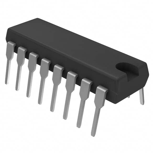
STMicroelectronics HCF4527BEY
- Part No.:
- HCF4527BEY
- Manufacturer:
- STMicroelectronics
- Category:
- Specialty Logic
- Package:
- 16-DIP (0.300", 7.62mm)
- Datasheet:
-
 HCF4527BEY.pdf
- Description:
- IC MULTIPEXER BCD RATE 16-DIP
- Quantity:
- Payment:

- Shipping:

Inventory:3,433
Please send an inquiry. Send us your inquiry, and we will respond immediately.
Product details
Overview
HCF4527BEY from STMicroelectronics is a BCD rate multiplier IC in 16-pin DIP package, performing digital pulse rate multiplication (e.g., 8 output pulses per 10 clock inputs when BCD=8), with cascading capability for multi-digit fractional scaling, 3–20 V supply range, and ±100 nA input leakage at 18 V. It enables arithmetic synthesis, A/D-D/A support, and frequency division in analog-digital hybrid systems.
For engineers reviewing the HCF4527BEY datasheet, HCF4527BEY pinout, HCF4527BEY application, or HCF4527BEY equivalent, key selection criteria include BCD-selectable pulse ratio accuracy, cascade timing compatibility (tPLH ≤ 90 ns @15 V), inhibit/carry propagation behavior, and DC parametric stability across 3–20 V operation.
Technical Context
The HCF4527BEY implements a synchronous 4-bit BCD-controlled digital rate multiplier using CMOS logic, where output pulse count per clock cycle equals (BCD input × clock count)/10. Its internal counter and combinational logic generate precise fractional rates without external feedback loops.
Cascade functionality supports two modes: ADD mode sums weighted fractions (e.g., 9/10 + 4/100 = 94/100), while MULTIPLY mode composes ratios (e.g., (9/10) × (4/10) = 36/100). Strobe, inhibit, set-to-9, and clear inputs enable synchronized multi-stage control and carry handling.
Key Specifications
| Parameter | Value and Actual Design Meaning |
|---|---|
| Supply Voltage Range | 3 V to 20 V - supports single-rail operation across 5 V, 10 V, and 15 V logic systems without level shifting |
| Input Leakage Current | ±100 nA max at VDD = 18 V - ensures minimal loading on upstream BCD sources and stable state retention |
| Max Clock Frequency | 3.5 MHz min @15 V - defines upper limit for real-time pulse generation in analog computation circuits |
| Propagation Delay (CLK→OUT) | 45–90 ns @15 V - determines minimum inter-stage timing margin in cascaded configurations |
| Output Drive (Sink/Source) | ±1.1 mA min @5 V - sufficient to drive TTL loads or subsequent CMOS stages directly |
| Quiescent Current | 0.08 µA typ @5 V, 3000 µA max @20 V - enables ultra-low-power standby in battery-backed instrumentation |
| Noise Margin | 2.5 V min @15 V - guarantees robust noise immunity in industrial environments with EMI exposure |
Pinout & Package
Package: 16-pin plastic DIP (0.300" width), JEDEC MS-001AC compliant, with 2.54 mm pin pitch and 17.78 mm body width.
| Pin/Terminal | Circuit Role | Design Meaning |
|---|---|---|
| 1 | "9" OUT | Active-high signal indicating BCD input equals decimal 9; used for overflow detection or digit chaining |
| 2–3, 14–15 | A, B, C, D | BCD-coded rate select inputs (LSB to MSB); define multiplication factor as N/10 where N = 0–9 |
| 4 | SET TO "9" | Asynchronous preset forcing internal counter to decimal 9; enables fast initialization or error recovery |
| 5–6 | OUT, OUT | Dual complementary rate outputs - one inverted, one non-inverted - for differential signaling or logic flexibility |
| 7 | INHIBIT OUT | Carry output indicating full-scale completion (N=9); synchronizes cascaded stage enable/disable |
| 8 | VSS | Negative supply reference (GND); must be connected to system ground plane for noise control |
| 9 | CLOCK | Primary timing input controlling pulse generation rate; edge-triggered with 50% duty cycle requirement |
| 10 | STROBE | Edge-sensitive latch enabling BCD input sampling; isolates rate setting from clock domain jitter |
| 11 | INHIBIT IN | Asynchronous inhibit gate disabling output pulses; functions as carry-in for cascaded addition mode |
| 12 | CASCADE | Internal cascade control node - connects to STROBE of next stage in MULTIPLY mode configurations |
| 13 | CLEAR | Asynchronous reset clearing internal counter and outputs; required before new BCD value loading |
| 16 | VDD | Positive supply rail (3–20 V); decoupling capacitor (100 nF) recommended within 1 cm of pin |
Key Features
| Feature | Design Value |
|---|---|
| Cascadable 4-bit BCD rate multiplication | Enables multi-digit fractional scaling (e.g., 94/100 or 36/100) without microcontroller intervention |
| Symmetrical output drive characteristics | Matched rise/fall times (40–80 ns) and sink/source current ensure clean waveform integrity in analog synthesis |
| Set-to-9 and Clear inputs | Supports deterministic initialization and error recovery in closed-loop computational circuits |
| 100% tested quiescent current | Guarantees low-power operation in battery-powered instrumentation and portable test equipment |
| JEDEC JESD13B compliance | Ensures interoperability with legacy B-series CMOS logic families and predictable timing margins |
Applications
| Function Generator Calibration | Analog-Digital Hybrid Controller |
|---|---|
Use Scenario: Generating precise calibration waveforms (e.g., 0.9×, 0.45× reference frequency) for oscilloscope and spectrum analyzer self-test routines. IC Role / Device Role / Timing Role: Rate multiplier providing programmable sub-harmonic clock division with BCD-settable integer numerator and fixed denominator of 10. Use Value: Eliminates need for crystal oscillators or PLLs in mid-frequency calibration signals, reducing BOM cost and board space. | Use Scenario: Controlling PWM duty cycle in motor drive feedback loops where analog error voltage is converted to BCD and scaled for actuator response. IC Role / Device Role / Timing Role: Digital pulse scaler converting analog-derived BCD commands into proportional timing signals for gate driver enable duration. Use Value: Enables linear analog-domain control with digital precision, avoiding ADC/DAC conversion latency and quantization error. |
| Programmable Frequency Divider | Legacy Instrumentation Upgrade |
Use Scenario: Replacing fixed-ratio dividers in vintage frequency synthesizers requiring field-adjustable division ratios (e.g., 3/10, 7/10). IC Role / Device Role / Timing Role: Cascaded BCD rate multiplier acting as reconfigurable divider with 0.1-step resolution over 0–0.9 range. Use Value: Restores serviceability in discontinued test gear by substituting obsolete discrete divider networks with single-IC solution. | Use Scenario: Retrofitting analog chart recorders with digital setpoint inputs, where BCD thumbwheel switches drive real-time pen speed modulation. IC Role / Device Role / Timing Role: Pulse rate translator mapping manual BCD entry to variable-speed stepper motor clocking via output pulse density. Use Value: Preserves mechanical design while adding digital configurability-no firmware or processor required. |
Equivalent & Alternatives
The following parts are listed as comparable options for similar BCD rate multiplier applications.
| Alternative Part | Technical Difference | Application Difference | Selection Advice |
|---|---|---|---|
| CD4527BE | Same functional architecture but TI-specified; slightly higher tPLH (120 ns @15 V vs. 90 ns) and no 100% IQ test guarantee | Compatible in static BCD applications; marginal for high-speed cascade timing due to longer propagation delay | Select when sourcing from TI-authorized channels or when legacy CD4000-series footprint compatibility is mandatory |
| MC14527B | Onsemi variant with identical pinout; wider VDD range (3–18 V), lower max fCL (2.8 MHz @15 V), and no cascade timing characterization data published | Suitable for low-frequency instrumentation; not recommended for multi-stage multiply-mode designs requiring tight skew control | Prefer for cost-sensitive replacements where absolute timing precision is secondary to availability |
Compared with CD4527BE and MC14527B, the HCF4527BEY offers tighter propagation delay control, guaranteed quiescent current testing, and documented cascade timing - making it optimal for multi-stage analog computation and precision frequency synthesis where deterministic behavior is critical.
Availability
HCF4527BEY is available at Aetrix Electronics and suitable for function generator calibration, analog-digital hybrid controllers, and programmable frequency division requiring stable component supply across extended temperature ranges (-55°C to +125°C).
Supply support for HCF4527BEY includes scheduled delivery planning, volume procurement assistance, BOM continuity management, traceable sourcing, and lifecycle availability coordination for OEM customers, industrial embedded developers, connected-device designers, and electronics production programs.
Manufacturer
STMicroelectronics is a global semiconductor leader headquartered in Geneva, designing and manufacturing analog, digital, and mixed-signal ICs for industrial, automotive, and consumer applications.
The HCF4527BEY belongs to ST's legacy B-series CMOS logic family, engineered specifically for analog-computation support, precision pulse scaling, and retrofit compatibility in measurement and control instrumentation.
FAQ
What is the maximum operating supply voltage for HCF4527BEY?
The absolute maximum supply voltage is +22 V, but the recommended operating range is 3 V to 20 V. Operation above 20 V risks permanent damage, while below 3 V may cause unreliable output transitions. The device is fully characterized at 5 V, 10 V, and 15 V, with quiescent current and propagation delays specified across this full range.
Can HCF4527BEY be used without cascading?
Yes - the HCF4527BEY operates independently as a single-digit rate multiplier (N/10, N = 0–9). All control inputs (STROBE, CLEAR, SET TO "9") and outputs (OUT, "9" OUT, INHIBIT OUT) function fully without connection to other units. Cascading is optional and only required for multi-digit fractional scaling beyond 0.9.
How does the INHIBIT IN pin affect output behavior?
The INHIBIT IN pin is an asynchronous active-low gate that disables all output pulses when asserted (logic low), regardless of clock or BCD input state. When deasserted (high), normal rate multiplication resumes immediately on the next clock edge. It also serves as carry-in in ADD-mode cascading, synchronizing stage enable timing.
Is HCF4527BEY still in active production?
No - STMicroelectronics has marked HCF4527BEY as obsolete. However, Aetrix Electronics maintains verified legacy stock with full traceability, including original manufacturer date codes and humidity indicator compliance. Engineering samples and small-batch production support remain available under controlled lifecycle management protocols.
HCF4527BEY Specifications
- Product attributes
- Attribute value
- Manufacturer:
- STMicroelectronics
- Series:
- 4000B
- Package/Case:
- 16-DIP (0.300", 7.62mm)
- Packaging:
- Tube
- Product Status:
- Obsolete
- Logic Type:
- BCD Rate Multiplier
- Supply Voltage:
- 3V ~ 20V
- Number of Bits:
- 4
- Operating Temperature:
- -55°C ~ 125°C
- Grade:
- -
- Qualification:
- -
- Mounting Type:
- Through Hole
- Supplier Device Package:
- 16-DIP
HCF4527BEY FAQ
1.How can I place an order for HCF4527BEY through Aetrix?
Please submit a Request for Quotation (RFQ) for HCF4527BEY on Aetrix. Our sales agent will provide a competitive quotation and guide you through the order confirmation once you accept the terms.
2.Are the price and stock information for HCF4527BEY reliable?
The price and inventory of HCF4527BEY are updated periodically and may fluctuate due to market conditions. Stock and pricing data are typically refreshed every 24 hours. Quotation validity for HCF4527BEY is usually 5 days.
3.What payment methods are accepted for HCF4527BEY?
We accept Wire Transfer, PayPal, Credit Card, Western Union, MoneyGram, and Escrow for HCF4527BEY transactions.
Note: Certain payment methods may incur a processing fee.
4.How is shipping managed for HCF4527BEY?
HCF4527BEY orders can be shipped via leading logistics carriers, including DHL, UPS, FedEx, TNT, or Registered Mail.
Once your HCF4527BEY order is processed, you will receive an email with the shipment details and tracking number.
Note: Tracking information may take up to 24 hours to appear. Express delivery typically takes 3–5 business days.
5.How can I obtain technical support or documentation for HCF4527BEY?
For technical support, including HCF4527BEY datasheets, pinout diagrams, or application guidance, please contact our engineering support team. They can provide detailed documentation and assistance for your HCF4527BEY requirements.
6.How does Aetrix verify that HCF4527BEY is sourced from the original manufacturer or authorized distributors?
All HCF4527BEY products on Aetrix are procured from qualified distributors and authorized channels. Our dedicated quality assurance team conducts strict verification, including traceability checks and, if necessary, third-party testing. This ensures that HCF4527BEY meets industry standards.
7.What is the process for return or replacement of HCF4527BEY?
All HCF4527BEY units undergo pre-shipment inspection (PSI). If there is an issue with HCF4527BEY, returns or replacements are accepted under the following conditions:
1.Quantity discrepancies, incorrect items, or visible external defects (such as breakage or corrosion), acknowledged by Aetrix.
2.The issue is reported within 90 days of delivery.
3.The HCF4527BEY part is unused and in its original packaging.
Return procedure for HCF4527BEY:
1.Submit a request within 90 days.
2.Obtain a Return Material Authorization (RMA) from Aetrix.
HCF4527BEY Tags

-
MC14490DWR2G
onsemi
-
SY58600UMG-TR
Microchip Technology

-
MC100EP16DTR2G
onsemi
-
MC100EP16MNR4G
onsemi
-
74LVC1GX04GW,125
Nexperia USA Inc.

-
CD4007UBE
Texas Instruments
-
NXS0104PWJ
Nexperia USA Inc.

-
CD74HC283M96
Texas Instruments

-
SN74LVC1GX04DCKR
Texas Instruments

-
SN74F283N
Texas Instruments
-
SN74LVC1404DCTR
Texas Instruments

-
SN74LVC1GX04DBVR
Texas Instruments
Tech Hub

A practical engineering and sourcing framework covering lifecycle verification, lifetime-buy calculations, replacement qualification, supplier checks and counterfeit-risk controls.

TTL and CMOS logic families differ in thresholds, loading, output drive, power and timing. This engineering guide compares 74HC and 74HCT, calculates noise margins and checks 3.3 V/5 V compatibility.

A practical engineering guide to 3.3V and 5V logic compatibility, input thresholds, resistor dividers, translator ICs, MOSFET level shifting, I2C pull-ups, timing limits and power-sequencing risks.

The 74HC595 uses push-pull logic outputs, while the TPIC6B595 uses 50 V open-drain DMOS sinks for higher-power loads. This guide compares timing, current limits, 3.3 V interfacing, load wiring, thermal…

The 74HC595 converts serial data into eight stable parallel outputs. This guide covers pin functions, shift and storage timing, OE and MR behavior, drive-current limits, cascading, voltage compatibilit…

A technical comparison of level-sensitive latches and edge-triggered flip-flops, covering timing windows, setup and hold limits, master–slave operation, time borrowing, race-through, HDL inference and…

A D latch stores one bit while Enable controls when data can pass. This reference covers gate-level operation, truth tables, transparency, setup and hold timing, LE versus OE, common ICs and practical …

An SR latch stores one bit through cross-coupled feedback. This engineering reference covers NOR and NAND implementations, truth tables, forbidden-state recovery, gated operation, switch debouncing, fa…

Latch circuits retain one bit through feedback. This technical reference covers SR and D latches, truth tables, transparency, timing limits, latch-versus-flip-flop behavior, applications and common log…

An engineering guide to LED driver operation, constant-current and constant-voltage outputs, linear and switching topologies, dimming, IC selection, calculations, replacement compatibility, and fault c…


