
 My Inquiry
 My Account


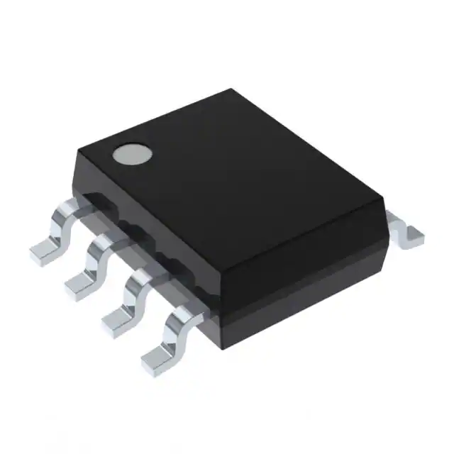
Renesas HFA1105IB
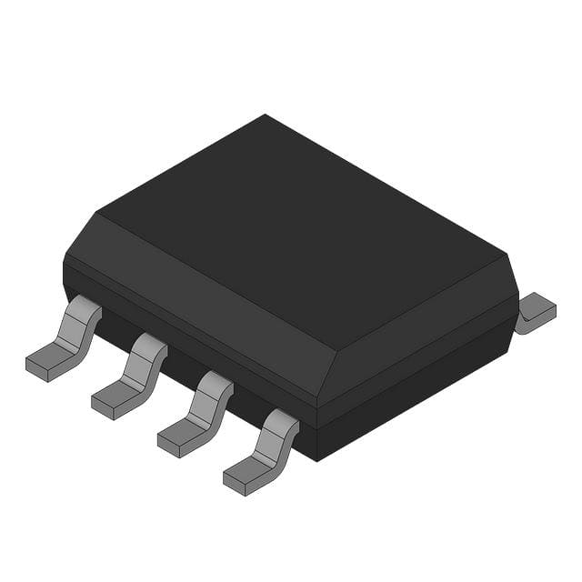
- Part No.:
- HFA1105IB
- Manufacturer:
- Renesas
- Category:
- Video Amps and Modules
- Package:
- 8-SOIC (0.154", 3.90mm Width)
- Datasheet:
-
 HFA1105IB.pdf
- Description:
- IC AMP CURRENT FEEDBACK 8SOIC
- Quantity:
- Payment:

- Shipping:

Inventory:3,358
Please send an inquiry. Send us your inquiry, and we will respond immediately.
Product details
Overview
HFA1105IB from Intersil is a 330MHz current feedback video operational amplifier in an 8-lead SOIC package, featuring 1000V/µs slew rate, ±0.1dB gain flatness to 75MHz, 0.08Ω closed-loop output impedance, and 5.8mA supply current - optimized for driving Flash ADCs and interfacing with video crosspoint switches like HA4201 and HA4314.
For engineers reviewing the HFA1105IB datasheet, HFA1105IB pinout, HFA1105IB application, or HFA1105IB equivalent, this page delivers verified specifications, SOIC-8 terminal mapping, video-system design context, and validated alternatives for video signal conditioning, high-speed data acquisition, and professional video routing.
Technical Context
The HFA1105IB uses Intersil's UHF-1 complementary bipolar process to implement a current feedback architecture with transimpedance gain of 500kΩ, enabling wide bandwidth independent of closed-loop gain configuration. Its quasi-complementary output stage delivers high drive capability while maintaining low quiescent current.
It requires a fixed feedback resistor (510Ω at AV = +2) rather than capacitive feedback, and exhibits asymmetrical slew rates (+1000V/µs / –650V/µs at AV = +1) due to its composite pulldown transistor switching behavior near 0V - a key consideration for bipolar video signals.
Key Specifications
| Parameter | Value and Actual Design Meaning |
|---|---|
| -3dB Bandwidth | 330MHz at AV = +2 - supports full HD video bandwidth and fast settling in digitizing systems. |
| Slew Rate | +1000V/µs (AV = +1) - enables clean 5VP-P pulse response with ≤1.4ns rise time. |
| Gain Flatness | ±0.1dB to 75MHz - ensures minimal amplitude distortion across NTSC/PAL baseband video spectrum. |
| Differential Gain/Phase | 0.02% / 0.03° at 3.58MHz - meets broadcast-grade video fidelity requirements for RGB and composite signals. |
| Output Impedance | 0.08Ω (DC) - provides low-impedance drive into 75Ω/150Ω video loads without gain loss or mismatch. |
| Supply Current | 5.8mA (±5V) - enables low-power operation in battery-powered or thermally constrained video equipment. |
| Input Impedance | 1MΩ non-inverting input - minimizes loading on preceding video sources or filters. |
Pinout & Package
Package: 8-lead narrow-body SOIC (JEDEC MS-012-AA, M8.15), -40°C to +85°C operating range, Pb-free anneal option available (HFA1105IBZ96).
| Pin/Terminal | Circuit Role | Design Meaning |
|---|---|---|
| 1, 4, 8 | No Connect (NC) | Internally unconnected; must remain floating - no external tie required or recommended. |
| 2 | Inverting Input (-IN) | Current-summing node for feedback network; sensitive to parasitic capacitance - keep trace short and ground plane removed. |
| 3 | Non-Inverting Input (+IN) | High-impedance input (1MΩ); DC source impedance ≥50Ω required for stability in inverting configurations. |
| 5 | Negative Supply (V-) | Connect to -5V rail; substrate potential should be tied to V- per die specification. |
| 6 | Output (OUT) | Low-impedance current-source output; series resistor (RS) required when driving >10pF capacitive loads. |
| 7 | Positive Supply (V+) | Connect to +5V rail; decouple with 10µF tantalum + 0.1µF ceramic per supply pin. |
Key Features
| Feature | Design Value |
|---|---|
| Current Feedback Architecture | Enables stable 330MHz bandwidth at AV = +2 with fixed 510Ω feedback resistor - avoids gain-dependent bandwidth roll-off typical of voltage-feedback op amps. |
| Video-Optimized Linearity | 0.02% differential gain and 0.03° differential phase at 3.58MHz ensure broadcast-compliant color fidelity in composite and component video paths. |
| Low-Power High-Speed Operation | 58mW total power dissipation (±5V, 5.8mA) allows integration into compact, fanless video digitizers and portable RF equipment. |
| Flash ADC Driver Capability | 0.08Ω output impedance and 1000V/µs slew rate deliver fast, low-distortion transient response into 50Ω–100Ω ADC input loads. |
| Pb-Free RoHS Compliance | Pb-free plus anneal construction (M8.15 package) ensures compatibility with SnPb and Pb-free reflow profiles per IPC/JEDEC J-STD-020. |
Applications
| Flash A/D Drivers | Video Switching and Routing |
|---|---|
Use Scenario: Driving the analog input of 8-bit–12-bit Flash ADCs in real-time video digitizers. IC Role / Device Role / Timing Role: Buffer and level-shift video signal while preserving edge integrity and minimizing aperture jitter. Use Value: 1000V/µs slew rate and 0.08Ω output impedance reduce settling error to <0.1% in ≤15ns, directly improving effective resolution. |
Use Scenario: Interfacing between Intersil video crosspoint switches (HA4201, HA4314) and downstream processing stages. IC Role / Device Role / Timing Role: Rebuffering switched video outputs to restore signal integrity degraded by switch channel capacitance and trace losses. Use Value: 330MHz bandwidth and ±0.1dB gain flatness maintain sync tip-to-white peak fidelity across all standard-definition video formats. |
| Professional Video Processing | RGB Preamps |
Use Scenario: Signal conditioning in broadcast camera heads, vision mixers, and waveform monitors. IC Role / Device Role / Timing Role: Active termination and gain staging for Y/C or component (Y/Pb/Pr) video paths prior to encoding or display. Use Value: 0.02% differential gain and 0.03° differential phase meet SMPTE RP 168 and ITU-R BT.601 broadcast linearity requirements. |
Use Scenario: Amplifying RGB signals from image sensors or graphics controllers before HDMI/DVI transmission. IC Role / Device Role / Timing Role: DC-coupled gain block with unity or modest gain (AV = +1 to +2) to match source-to-load impedance and voltage swing. Use Value: 1MΩ input impedance prevents loading of high-Z sensor outputs, while 330MHz bandwidth preserves pixel clock harmonics up to 1080p60. |
Equivalent & Alternatives
The following parts are listed as comparable options for similar current feedback video amplifier applications.
| Alternative Part | Technical Difference | Application Difference | Selection Advice |
|---|---|---|---|
| CLC406 | Lower bandwidth (200MHz), higher supply current (7.5mA), same SOIC-8 pinout - direct drop-in replacement but with reduced speed and higher power. | Acceptable for SD video routing where 330MHz headroom is unnecessary; not suitable for >720p digitizing or fast-settling ADC drivers. | Select CLC406 only if legacy design reuse or cost sensitivity outweighs bandwidth and power advantages of HFA1105IB. |
| HFA1135 | Includes output limiting function (clamping), identical bandwidth (330MHz) and pinout, but slightly higher supply current (6.2mA). | Preferred in systems requiring protection against overvoltage transients at ADC inputs or downstream video DACs. | Choose HFA1135 when output clamping is needed; otherwise HFA1105IB offers lower power and simpler biasing. |
Compared with CLC406 and HFA1135, the HFA1105IB delivers optimal balance of 330MHz bandwidth, 5.8mA supply current, and video-grade linearity - making it the preferred choice for new designs targeting high-fidelity, low-power video signal conditioning without clamping requirements.
Availability
HFA1105IB is available at Aetrix Electronics and suitable for Flash ADC drivers, video switching/routing systems, and professional video processing equipment requiring stable component supply, long-term lifecycle support, and RoHS-compliant sourcing.
Supply support for HFA1105IB includes scheduled delivery planning, volume procurement assistance, BOM continuity management, traceable sourcing, and lifecycle availability coordination for OEM customers, industrial embedded developers, connected-device designers, and electronics production programs.
Manufacturer
Intersil Corporation (now part of Renesas Electronics) is a semiconductor manufacturer specializing in high-performance analog and mixed-signal ICs for precision timing, power management, and high-speed signal processing.
The HFA1105IB belongs to Intersil's HFA video amplifier family, designed specifically for broadcast, medical imaging, and instrumentation applications demanding ultra-low distortion, wide bandwidth, and robust drive capability in compact packages.
FAQ
What is the maximum recommended load capacitance for stable operation of the HFA1105IB?
The HFA1105IB requires a series output resistor (RS) when driving capacitive loads. For AV = +1, Figure 1 in the FN3395 datasheet shows stable operation up to 400pF with RS = 8Ω, though bandwidth drops to 75MHz. Loads >10pF must include RS; 0Ω output connection is unstable with any significant capacitance. The HFA1105IB itself does not specify a hard maximum CL, but practical limit is ~500pF with appropriate RS tuning.
Is the HFA1105IB pin-compatible with the CLC406, and what are the implications for board reuse?
Yes, the HFA1105IB is explicitly documented as a pin-compatible upgrade for the CLC406 in the FN3395 datasheet. Both use identical 8-lead SOIC (M8.15) packaging and share the same NC/-IN/+IN/V-/OUT/V+/NC/NC pinout. Board reuse is straightforward, but note that HFA1105IB draws less supply current (5.8mA vs. 7.5mA) and delivers higher bandwidth (330MHz vs. 200MHz), so existing compensation networks may require verification.
Does the HFA1105IB support single-supply operation, or is dual-supply mandatory?
The HFA1105IB is specified exclusively for dual-supply operation: ±4.5V to ±5.5V (±5V typical). Its input common-mode range is ±1.2V to ±2.4V, and output swing is symmetric about ground (±3.4V into 100Ω). Single-supply use is not supported - no rail-to-rail input/output capability, and V- must be actively biased below ground. Attempting single-supply operation violates absolute maximum ratings and degrades video performance.
How does the asymmetrical slew rate of the HFA1105IB affect video signal fidelity, and when is it most critical?
The HFA1105IB exhibits asymmetrical slew rates (+1000V/µs / –650V/µs at AV = +1) due to its quasi-complementary output stage, causing increased undershoot on negative-going edges. This is most critical for bipolar video waveforms (e.g., sync pulses, composite video) where overshoot/undershoot imbalance introduces differential phase errors. For unipolar signals (e.g., RGB positive-only), slew symmetry is restored, preserving fidelity.
What is the thermal resistance (θJA) of the HFA1105IB in its SOIC package, and how does it impact layout decisions?
The HFA1105IB in 8-lead SOIC has a typical junction-to-ambient thermal resistance (θJA) of 165°C/W, measured on an evaluation board in free air. At 58mW dissipation, this yields ~9.6°C junction-to-ambient rise - acceptable for most video PCBs. However, the datasheet mandates a solid ground plane and localized decoupling (10µF + 0.1µF per supply pin) to manage high-frequency current return paths and prevent thermal-induced gain instability.
HFA1105IB Specifications
- Product attributes
- Attribute value
- Manufacturer:
- Renesas
- Package/Case:
- 8-SOIC (0.154", 3.90mm Width)
- Series:
- -
- Packaging:
- Tube
- Product Status:
- Obsolete
- Applications:
- Current Feedback
- Output Type:
- -
- Number of Circuits:
- 1
- -3db Bandwidth:
- 330 MHz
- Slew Rate:
- 1000V/µs
- Current - Supply:
- 5.8 mA
- Current - Output / Channel:
- 60 mA
- Voltage - Supply, Single/Dual (±):
- ±4.5V ~ 5.5V
- Mounting Type:
- Surface Mount
- Grade:
- -
- Qualification:
- -
- Supplier Device Package:
- 8-SOIC
HFA1105IB FAQ
1.How can I place an order for HFA1105IB through Aetrix?
Please submit a Request for Quotation (RFQ) for HFA1105IB on Aetrix. Our sales agent will provide a competitive quotation and guide you through the order confirmation once you accept the terms.
2.Are the price and stock information for HFA1105IB reliable?
The price and inventory of HFA1105IB are updated periodically and may fluctuate due to market conditions. Stock and pricing data are typically refreshed every 24 hours. Quotation validity for HFA1105IB is usually 5 days.
3.What payment methods are accepted for HFA1105IB?
We accept Wire Transfer, PayPal, Credit Card, Western Union, MoneyGram, and Escrow for HFA1105IB transactions.
Note: Certain payment methods may incur a processing fee.
4.How is shipping managed for HFA1105IB?
HFA1105IB orders can be shipped via leading logistics carriers, including DHL, UPS, FedEx, TNT, or Registered Mail.
Once your HFA1105IB order is processed, you will receive an email with the shipment details and tracking number.
Note: Tracking information may take up to 24 hours to appear. Express delivery typically takes 3–5 business days.
5.How can I obtain technical support or documentation for HFA1105IB?
For technical support, including HFA1105IB datasheets, pinout diagrams, or application guidance, please contact our engineering support team. They can provide detailed documentation and assistance for your HFA1105IB requirements.
6.How does Aetrix verify that HFA1105IB is sourced from the original manufacturer or authorized distributors?
All HFA1105IB products on Aetrix are procured from qualified distributors and authorized channels. Our dedicated quality assurance team conducts strict verification, including traceability checks and, if necessary, third-party testing. This ensures that HFA1105IB meets industry standards.
7.What is the process for return or replacement of HFA1105IB?
All HFA1105IB units undergo pre-shipment inspection (PSI). If there is an issue with HFA1105IB, returns or replacements are accepted under the following conditions:
1.Quantity discrepancies, incorrect items, or visible external defects (such as breakage or corrosion), acknowledged by Aetrix.
2.The issue is reported within 90 days of delivery.
3.The HFA1105IB part is unused and in its original packaging.
Return procedure for HFA1105IB:
1.Submit a request within 90 days.
2.Obtain a Return Material Authorization (RMA) from Aetrix.
HFA1105IB Tags

-
LT6552CS8#PBF
Analog Devices Inc.
-
LT6205IS5#TRPBF
Analog Devices Inc.
-
LT6206IMS8#TRPBF
Analog Devices Inc.
-
LT6552CDD#PBF
Analog Devices Inc.
-
LT6552IS8#PBF
Analog Devices Inc.
-
LT1252CS8#PBF
Analog Devices Inc.
-
AD818ARZ-REEL7
Analog Devices Inc.

-
MAX4310EUA+
Analog Devices Inc./Maxim Integrated
-
AD829ARZ
Analog Devices Inc.
-
AD810ARZ
Analog Devices Inc.
-
MAX4310ESA+
Analog Devices Inc./Maxim Integrated
-
MAX4313ESA+
Analog Devices Inc./Maxim Integrated
Tech Hub

TTL and CMOS logic families differ in thresholds, loading, output drive, power and timing. This engineering guide compares 74HC and 74HCT, calculates noise margins and checks 3.3 V/5 V compatibility.

A practical engineering guide to 3.3V and 5V logic compatibility, input thresholds, resistor dividers, translator ICs, MOSFET level shifting, I2C pull-ups, timing limits and power-sequencing risks.

The 74HC595 uses push-pull logic outputs, while the TPIC6B595 uses 50 V open-drain DMOS sinks for higher-power loads. This guide compares timing, current limits, 3.3 V interfacing, load wiring, thermal…

The 74HC595 converts serial data into eight stable parallel outputs. This guide covers pin functions, shift and storage timing, OE and MR behavior, drive-current limits, cascading, voltage compatibilit…

A technical comparison of level-sensitive latches and edge-triggered flip-flops, covering timing windows, setup and hold limits, master–slave operation, time borrowing, race-through, HDL inference and…

A D latch stores one bit while Enable controls when data can pass. This reference covers gate-level operation, truth tables, transparency, setup and hold timing, LE versus OE, common ICs and practical …

An SR latch stores one bit through cross-coupled feedback. This engineering reference covers NOR and NAND implementations, truth tables, forbidden-state recovery, gated operation, switch debouncing, fa…

Latch circuits retain one bit through feedback. This technical reference covers SR and D latches, truth tables, transparency, timing limits, latch-versus-flip-flop behavior, applications and common log…

An engineering guide to LED driver operation, constant-current and constant-voltage outputs, linear and switching topologies, dimming, IC selection, calculations, replacement compatibility, and fault c…

Operational amplifier guide covering op amp basics, feedback, ideal vs real op amps, common configurations, buffer circuits, offset, bias current, gain-bandwidth, slew rate, rail-to-rail limits and sel…


