
 My Inquiry
 My Account


Analog Devices Inc. HMC676LC3CTR-R5
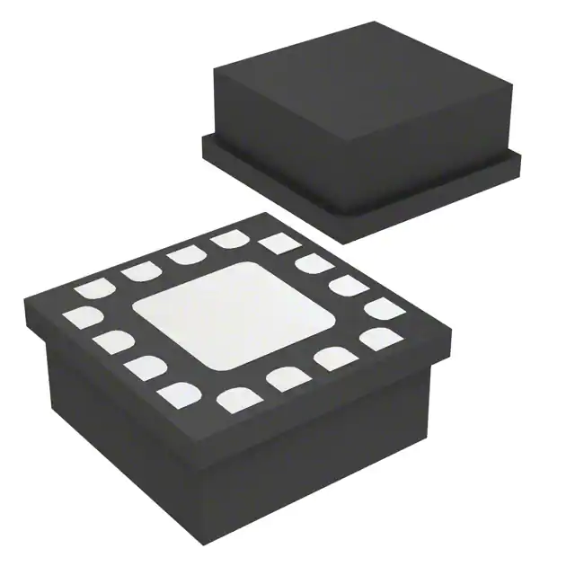
- Part No.:
- HMC676LC3CTR-R5
- Manufacturer:
- Analog Devices Inc.
- Category:
- Comparators
- Package:
- 16-LFQFN Exposed Pad
- Datasheet:
-
 HMC676LC3CTR-R5.pdf
- Description:
- IC COMPARATOR 1 GEN PUR 16SMT
- Quantity:
- Payment:

- Shipping:

Inventory:2,634
Please send an inquiry. Send us your inquiry, and we will respond immediately.
Product details
Overview
HMC676LC3CTR-R5 from Analog Devices (formerly Hittite Microwave) is a SiGe monolithic latched comparator with RSECL output stage, designed for ultra-high-speed signal acquisition in 10 Gbps data paths. It delivers 100 ps propagation delay, 60 ps minimum input pulse width, and 0.2 ps rms random jitter, operating with ±1.75 V differential input range and driving 400 mV into 50 Ω terminated to –2 V - ideal for clock/data restoration in high-speed test and communications systems.
For engineers reviewing the HMC676LC3CTR-R5 datasheet, HMC676LC3CTR-R5 pinout, HMC676LC3CTR-R5 application, or HMC676LC3CTR-R5 equivalent, key selection criteria include latch-mode vs. track-mode operation, resistor-programmable hysteresis, RSECL output compatibility with –2 V termination, and thermal performance under 120 mW dissipation at –40 °C to +85 °C.
Technical Context
The HMC676LC3CTR-R5 integrates three functional blocks: a high-gain input amplifier, a level-sensitive single-shot latch, and an RSECL output buffer. Its latch control uses complementary LE/LE_bar inputs with 8 kΩ impedance and supports both transparent (track) and hold (latch) modes based on differential latch enable state.
Input stage features 50 Ω differential impedance, 350 kΩ common-mode impedance, and 15 µV/°C offset drift; output stage delivers 320–400 mV differential swing with 23 ps rise / 13 ps fall time (20%–80%), while PSRR is 38 dB on both Vcci and Vee rails.
Key Specifications
| Parameter | Value and Actual Design Meaning |
|---|---|
| Equivalent Input Bandwidth | 10 GHz typical - enables accurate digitization of sub-100 ps pulses in broadband ATE and instrumentation. |
| Propagation Delay | 100 ps typical - ensures deterministic timing alignment in 10 Gbps serial data recovery paths. |
| Random Jitter (RJ) | 0.2 ps rms at 10 Gbps - minimizes eye closure in high-speed clock and data restoration circuits. |
| Minimum Pulse Width | 60 ps - supports detection of ultra-narrow pulses in pulse spectroscopy and trigger applications. |
| Power Dissipation | 120 mW at TA = +25 °C - requires thermal management via exposed paddle soldered to Vee ground plane. |
| Hysteresis Control | Resistor-programmable via HYS pin - allows precise noise immunity tuning without external components. |
| Output Swing | 350 mV typical into 50 Ω terminated to –2 V - directly interfaces with standard RSECL logic receivers. |
Pinout & Package
16-lead 3×3 mm ceramic SMT package (alumina body, gold-over-nickel plating, MSL3), with exposed paddle requiring solder connection to Vee (–3 V) for thermal and ESD performance.
| Pin/Terminal | Circuit Role | Design Meaning |
|---|---|---|
| 1, 4 | VTP / VTN | Termination return pins for INP/INN - must be connected to respective input termination reference (e.g., –2 V or 2 V). |
| 2, 3 | INP / INN | Differential analog inputs with 50 Ω impedance - accept ±1.75 V differential swing and support AC/DC coupling. |
| 5, 16 | Vcci | +3.3 V supply for input stage - decoupling required near pins to suppress supply noise. |
| 6, 7 | LE / LE_bar | Complementary latch enable inputs - define track (LE–LE_bar low) or latch (LE–LE_bar high) mode; 8 kΩ input impedance. |
| 9, 12 | Vcco | 0 V output stage supply - sets RSECL logic high/low levels when terminated to –2 V. |
| 10, 11 | Q / Q_bar | Complementary RSECL outputs - deliver 350 mV swing, 23 ps rise / 13 ps fall time into 50 Ω loads. |
| 13 | Vee | –3 V negative supply - exposed paddle must be soldered to this node for thermal conduction and ESD path. |
| 14 | HYS | Hysteresis control - open for zero hysteresis; resistor to Vee sets hysteresis per graph (e.g., 10 kΩ ≈ ±1 mV). |
Key Features
| Feature | Design Value |
|---|---|
| Latch/Track Mode Selectability | Configurable via LE/LE_bar differential state - eliminates need for external mode-control logic in adaptive sampling systems. |
| RSECL Output Stage | Drives 400 mV into 50 Ω terminated to –2 V - enables direct interfacing with legacy ECL/PECL receivers without level-shifting. |
| Programmable Hysteresis | Set by single external resistor on HYS pin - provides adjustable noise margin without adding board area or BOM cost. |
| Low Overdrive Dispersion | 10 ps typical - ensures consistent timing across varying input amplitudes, critical for jitter-sensitive ATE applications. |
| High Input Bandwidth | 10 GHz equivalent input bandwidth - preserves fast edge integrity in >10 Gbps data acquisition front-ends. |
Applications
| ATE High-Speed Testing | Digital Receiver Front-End |
|---|---|
|
Use Scenario: Capturing 10 Gbps test patterns in automated wafer probe stations with sub-100 ps timing resolution. IC Role / Device Role / Timing Role: Latched comparator performing high-fidelity data sampling synchronized to precision strobe clocks. Use Value: 60 ps minimum pulse width and 100 ps propagation delay enable reliable capture of narrow test pulses without aliasing or metastability. |
Use Scenario: Recovering clock and data from degraded optical or RF baseband signals in coherent receiver subsystems. IC Role / Device Role / Timing Role: Clock/data restoration element converting analog waveforms into clean digital logic for downstream SerDes. Use Value: 0.2 ps rms random jitter and 10 GHz input bandwidth preserve signal integrity during retiming, minimizing BER degradation. |
| Pulse Spectroscopy Systems | High-Speed Trigger Generation |
|
Use Scenario: Detecting nanosecond-scale transient events in laser-induced breakdown spectroscopy or particle detection. IC Role / Device Role / Timing Role: Ultrafast threshold detector triggering acquisition windows with picosecond-level timing precision. Use Value: 10 ps overdrive dispersion and 100 ps propagation delay ensure repeatable trigger latency independent of pulse amplitude. |
Use Scenario: Generating synchronous start pulses for oscilloscopes, digitizers, or time-of-flight measurement units. IC Role / Device Role / Timing Role: Edge-detecting comparator providing deterministic, low-jitter trigger outputs aligned to input transitions. Use Value: 23 ps Q rise time and 13 ps Q fall time produce sharp, well-defined trigger edges compatible with <100 ps system timing budgets. |
Equivalent & Alternatives
The following parts are listed as comparable options for similar latched comparator applications.
| Alternative Part | Technical Difference | Application Difference | Selection Advice |
|---|---|---|---|
| ADCMP572BCPZ-R7 | CMOS output, 2.5 V supply, 85 ps propagation delay, no latch mode - operates only as tracking comparator. | Requires external latch or FPGA capture logic; unsuitable for standalone latched sampling at 10 Gbps. | Select when lower power (45 mW) and CMOS interfacing are prioritized over latch functionality and RSECL drive. |
| HMC874LC3C | Same 3×3 mm package, 12 GHz bandwidth, 90 ps propagation delay, but lacks programmable hysteresis and uses PECL outputs (–1.3 V termination). | Higher speed but incompatible termination scheme; requires redesign of output load network and biasing. | Select when >10 GHz bandwidth is mandatory and system already supports PECL signaling with –1.3 V termination. |
Compared with ADCMP572BCPZ-R7 and HMC874LC3C, the HMC676LC3CTR-R5 uniquely combines latch mode, RSECL output with –2 V termination, and resistor-programmable hysteresis in a thermally optimized 3×3 mm package - making it the only drop-in solution for legacy Hittite-based 10 Gbps ATE and instrumentation designs requiring minimal layout change.
Availability
HMC676LC3CTR-R5 is available at Aetrix Electronics and suitable for high-speed ATE systems, digital receiver front-ends, and pulse spectroscopy instruments requiring stable component supply across extended production lifecycles.
Supply support for HMC676LC3CTR-R5 includes scheduled delivery planning, volume procurement assistance, BOM continuity management, traceable sourcing, and lifecycle availability coordination for OEM customers, industrial embedded developers, connected-device designers, and electronics production programs.
Manufacturer
Analog Devices acquired Hittite Microwave in 2014 and maintains its high-frequency RF and microwave product lines, emphasizing performance-critical signal chain components for defense, test, and communications.
The HMC676LC3CTR-R5 belongs to Hittite's legacy high-speed comparator family, engineered specifically for sub-100 ps timing accuracy in automated test equipment and broadband instrumentation where deterministic jitter and latch-controlled sampling are essential.
FAQ
What is the operating temperature range for the HMC676LC3CTR-R5?
The HMC676LC3CTR-R5 is specified to operate from –40 °C to +85 °C ambient temperature. Junction temperature must not exceed 125 °C, and thermal design must account for 120 mW power dissipation using the exposed paddle soldered to Vee. Derating begins above 85 °C at 20.4 mW/°C, as defined in the absolute maximum ratings table. This range supports deployment in industrial-grade ATE and instrumentation environments.
Does the HMC676LC3CTR-R5 support both latch and track modes, and how is mode selection implemented?
Yes, the HMC676LC3CTR-R5 supports both latch (hold) and track (transparent) modes. Mode selection is controlled differentially via the LE and LE_bar pins: latch mode activates when LE–LE_bar is high; track mode activates when LE–LE_bar is low or both pins are floating. The latch is level-sensitive, not edge-triggered, and internal timing parameters (e.g., tS = 45 ps setup, tH = –42 ps hold) define valid acquisition windows. This dual-mode capability is intrinsic to the HMC676LC3CTR-R5 architecture and requires no external configuration registers.
What is the recommended termination for the RSECL outputs of the HMC676LC3CTR-R5?
The HMC676LC3CTR-R5 RSECL outputs require 50 Ω termination to –2 V (Vcco – 2 V), delivering a nominal 350 mV differential swing. Vcco is supplied at 0 V, so termination resistors must connect between each Q/Q_bar output and a –2 V rail. Input termination (INP/INN) may be referenced to –2 V (for DC coupling) or ground (for AC coupling), depending on source common-mode voltage. Proper termination is essential to achieve specified jitter, propagation delay, and output swing values in the HMC676LC3CTR-R5.
How is hysteresis configured on the HMC676LC3CTR-R5, and what is its practical impact?
Hysteresis on the HMC676LC3CTR-R5 is configured by connecting a resistor (Rhys) between the HYS pin and Vee (–3 V); open circuit yields zero hysteresis. Per the hysteresis vs. Rhys graph, a 10 kΩ resistor provides ~±1 mV hysteresis, improving noise immunity without degrading propagation delay. This feature directly reduces false triggering in noisy high-speed environments such as ATE test heads or RF receiver IF stages - a key differentiator of the HMC676LC3CTR-R5 versus fixed-threshold comparators.
Is the HMC676LC3CTR-R5 pin-compatible with other Hittite comparators like the HMC674LC3C or HMC874LC3C?
No, the HMC676LC3CTR-R5 is not pin-compatible with HMC674LC3C or HMC874LC3C. While all use the same 16-lead 3×3 mm package footprint, pin functions differ significantly: HMC676LC3CTR-R5 assigns pins 6/7 to complementary LE/LE_bar, whereas HMC874LC3C uses those pins for Vee and output enables. Additionally, HMC676LC3CTR-R5 places Vee on pin 13 with mandatory paddle connection, unlike HMC674LC3C's Vee distribution. Board-level replacement requires full schematic and layout revision - the HMC676LC3CTR-R5 must be treated as a unique pinout.
HMC676LC3CTR-R5 Specifications
- Product attributes
- Attribute value
- Manufacturer:
- Analog Devices Inc.
- Package/Case:
- 16-LFQFN Exposed Pad
- Series:
- -
- Packaging:
- Tape & Reel (TR)
- Product Status:
- Obsolete
- Type:
- General Purpose
- Number of Elements:
- 1
- Output Type:
- -
- Voltage - Supply, Single/Dual (±):
- 3.3V
- :
- 5mV
- Voltage - Input Offset (Max):
- 15µA
- Current - Input Bias (Max):
- 40mA
- Current - Output (Typ):
- 8mA
- Current - Quiescent (Max):
- 38dB PSRR
- CMRR, PSRR (Typ):
- 0.13ns
- Propagation Delay (Max):
- 1mV
- Hysteresis:
- -40°C ~ 85°C
- Operating Temperature:
- -
- Grade:
- -
- Qualification:
- Surface Mount
- :
- 16-SMT (3x3)
HMC676LC3CTR-R5 FAQ
1.How can I place an order for HMC676LC3CTR-R5 through Aetrix?
Please submit a Request for Quotation (RFQ) for HMC676LC3CTR-R5 on Aetrix. Our sales agent will provide a competitive quotation and guide you through the order confirmation once you accept the terms.
2.Are the price and stock information for HMC676LC3CTR-R5 reliable?
The price and inventory of HMC676LC3CTR-R5 are updated periodically and may fluctuate due to market conditions. Stock and pricing data are typically refreshed every 24 hours. Quotation validity for HMC676LC3CTR-R5 is usually 5 days.
3.What payment methods are accepted for HMC676LC3CTR-R5?
We accept Wire Transfer, PayPal, Credit Card, Western Union, MoneyGram, and Escrow for HMC676LC3CTR-R5 transactions.
Note: Certain payment methods may incur a processing fee.
4.How is shipping managed for HMC676LC3CTR-R5?
HMC676LC3CTR-R5 orders can be shipped via leading logistics carriers, including DHL, UPS, FedEx, TNT, or Registered Mail.
Once your HMC676LC3CTR-R5 order is processed, you will receive an email with the shipment details and tracking number.
Note: Tracking information may take up to 24 hours to appear. Express delivery typically takes 3–5 business days.
5.How can I obtain technical support or documentation for HMC676LC3CTR-R5?
For technical support, including HMC676LC3CTR-R5 datasheets, pinout diagrams, or application guidance, please contact our engineering support team. They can provide detailed documentation and assistance for your HMC676LC3CTR-R5 requirements.
6.How does Aetrix verify that HMC676LC3CTR-R5 is sourced from the original manufacturer or authorized distributors?
All HMC676LC3CTR-R5 products on Aetrix are procured from qualified distributors and authorized channels. Our dedicated quality assurance team conducts strict verification, including traceability checks and, if necessary, third-party testing. This ensures that HMC676LC3CTR-R5 meets industry standards.
7.What is the process for return or replacement of HMC676LC3CTR-R5?
All HMC676LC3CTR-R5 units undergo pre-shipment inspection (PSI). If there is an issue with HMC676LC3CTR-R5, returns or replacements are accepted under the following conditions:
1.Quantity discrepancies, incorrect items, or visible external defects (such as breakage or corrosion), acknowledged by Aetrix.
2.The issue is reported within 90 days of delivery.
3.The HMC676LC3CTR-R5 part is unused and in its original packaging.
Return procedure for HMC676LC3CTR-R5:
1.Submit a request within 90 days.
2.Obtain a Return Material Authorization (RMA) from Aetrix.
HMC676LC3CTR-R5 Tags

-
LM2903DR
Texas Instruments

-
LM339DR
Texas Instruments

-
LM339PWR
Texas Instruments

-
LM393DT
STMicroelectronics
-
LM2901PWR
Texas Instruments
-
LM2903DT
STMicroelectronics
-
LM393DR
Texas Instruments
-
LM239DR
Texas Instruments
-
LM339APWR
Texas Instruments

-
LM2903P
Texas Instruments
-
LM393ADR
Texas Instruments
-
NCX2200GMAZ
NXP Semiconductors
Tech Hub

A practical engineering guide to 3.3V and 5V logic compatibility, input thresholds, resistor dividers, translator ICs, MOSFET level shifting, I2C pull-ups, timing limits and power-sequencing risks.

The 74HC595 uses push-pull logic outputs, while the TPIC6B595 uses 50 V open-drain DMOS sinks for higher-power loads. This guide compares timing, current limits, 3.3 V interfacing, load wiring, thermal…

The 74HC595 converts serial data into eight stable parallel outputs. This guide covers pin functions, shift and storage timing, OE and MR behavior, drive-current limits, cascading, voltage compatibilit…

A technical comparison of level-sensitive latches and edge-triggered flip-flops, covering timing windows, setup and hold limits, master–slave operation, time borrowing, race-through, HDL inference and…

A D latch stores one bit while Enable controls when data can pass. This reference covers gate-level operation, truth tables, transparency, setup and hold timing, LE versus OE, common ICs and practical …

An SR latch stores one bit through cross-coupled feedback. This engineering reference covers NOR and NAND implementations, truth tables, forbidden-state recovery, gated operation, switch debouncing, fa…

Latch circuits retain one bit through feedback. This technical reference covers SR and D latches, truth tables, transparency, timing limits, latch-versus-flip-flop behavior, applications and common log…

An engineering guide to LED driver operation, constant-current and constant-voltage outputs, linear and switching topologies, dimming, IC selection, calculations, replacement compatibility, and fault c…

Operational amplifier guide covering op amp basics, feedback, ideal vs real op amps, common configurations, buffer circuits, offset, bias current, gain-bandwidth, slew rate, rail-to-rail limits and sel…

Jumper cables guide covering safe connection order, red and black clamp placement, final ground connection, cable gauge, length, clamp quality, copper vs CCA cables, jump starter comparison and battery…


