
 My Inquiry
 My Account


Analog Devices Inc. HMC974LC3C
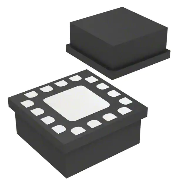
- Part No.:
- HMC974LC3C
- Manufacturer:
- Analog Devices Inc.
- Category:
- Comparators
- Package:
- 16-LFQFN Exposed Pad
- Datasheet:
-
 HMC974LC3C.pdf
- Description:
- IC COMPARATOR 1 WINDW 16SMT
- Quantity:
- Payment:

- Shipping:

Inventory:1,725
Please send an inquiry. Send us your inquiry, and we will respond immediately.
Product details
Overview
HMC974LC3C from Analog Devices is a silicon germanium (SiGe) monolithic ultra-fast window comparator with RSPECL output drivers, 88 ps input-to-output propagation delay, 11 GHz equivalent input bandwidth, and 60 ps minimum detectable pulse width. It operates in track or latch mode to determine whether an analog input lies above, below, or between two user-defined reference voltages (RT and RB), serving high-speed threshold detection in electronic warfare systems and clock/data restoration.
For engineers reviewing the HMC974LC3C datasheet, HMC974LC3C pinout, HMC974LC3C application, or HMC974LC3C equivalent, key selection considerations include its differential latch control, −3 V/3.3 V/2 V supply configuration, 16-terminal 2.9 mm × 2.9 mm LCC package, and single-ended negative logic outputs (URB, WOUTB, ORB) with 300–440 mV swing into 50 Ω.
Technical Context
The HMC974LC3C implements dual matched SiGe comparators at its input stage to ensure precise dc and dynamic matching while minimizing input capacitance. Its three independent outputs-URB (under-range), WOUTB (in-window), and ORB (over-range)-are level-latched and driven by reduced-swing PECL stages capable of delivering 400 mV into 50 Ω terminated loads.
It supports two operational modes: track mode for real-time window monitoring and latch mode enabled via complementary LE/LE inputs. Power sequencing requires VEE applied first (−3 V), followed by VCCI (3.3 V) and VCCO (2 V), with strict adherence to avoid latch-up or damage.
Key Specifications
| Parameter | Value and Actual Design Meaning |
|---|---|
| Propagation Delay | 88 ps typical input-to-output delay enables timing-critical sampling at >10 Gbps data rates. |
| Equivalent Input Bandwidth | 11 GHz allows accurate digitization of fast-rising edges with sub-100 ps transitions. |
| Minimum Detectable Pulse Width | 60 ps supports detection of ultra-narrow pulses in high-speed test and radar signal processing. |
| Output Voltage Swing | 300–440 mV into 50 Ω ensures robust noise margin and compatibility with standard PECL receivers. |
| Power Dissipation | 240 mW at TA = 25°C reflects optimized SiGe process efficiency for high-speed analog comparison. |
| Operating Temperature Range | −40°C to +85°C supports deployment in industrial and defense-grade embedded instrumentation. |
| Input Impedance | 50 Ω per input pair (WIN–RT, WIN–RB, RT–WIT, RB–WIT) simplifies 50 Ω RF interface design. |
Pinout & Package
The HMC974LC3C is housed in a 16-terminal 2.9 mm × 2.9 mm ceramic leadless chip carrier (LCC) with exposed pad requiring connection to VEE. The package is RoHS-compliant, MSL3-rated, and features gold-over-nickel terminations on alumina substrate.
| Pin/Terminal | Circuit Role | Design Meaning |
|---|---|---|
| 1 (RT) | Reference Top termination resistor node | Defines upper voltage threshold of window; must be biased via external 50 Ω to VTERM. |
| 2 (WIN) | Analog input window signal | Differential input node referenced to WIT; accepts ±2 V range with 1 pF input capacitance. |
| 3 (WIT) | Common-mode window termination | DC bias reference for WIN, RT, and RB; sets common-mode voltage (VCM = 0 V typical). |
| 4 (RB) | Reference Bottom termination return | Defines lower voltage threshold; forms window boundary with RT and determines URB assertion. |
| 5, 16 (VCCI) | Positive supply for input stage | +3.3 V supply powering comparator core; 10–20 mA draw under operation. |
| 6 (LE), 7 (LE) | Complementary latch enable inputs | LE low / LE high enables latch mode; both floating defaults to track mode. |
| 8, 14 (VEE) | Negative power supply | −3.0 V rail; exposed pad must be soldered directly to VEE plane for thermal and ESD integrity. |
| 9, 13 (VCCO) | Positive supply for output stage | +2.0 V supply powering RSPECL drivers; delivers 60–80 mA output-stage current. |
| 10 (URB) | Under-range output | Active-low signal asserted when WIN < RB; single-ended negative logic, 50 Ω terminated. |
| 11 (WOUTB) | Window output | Active-low signal asserted when RB < WIN < RT; used for in-band event detection. |
| 12 (ORB) | Over-range output | Active-low signal asserted when WIN > RT; enables high-threshold alarm or clipping control. |
| 15 (RTN) | ESD protection return | Internal ESD diode return path; must connect to local ground or VEE for safe discharge. |
Key Features
| Feature | Design Value |
|---|---|
| Dual matched SiGe comparators | Ensures <±4 mV offset matching and <30 μA input bias current for precise window symmetry. |
| RSPECL output drivers | Deliver 300–440 mV swing into 50 Ω without external level-shifting, reducing BOM count and layout complexity. |
| Track/latch dual-mode operation | Enables real-time monitoring (track) or edge-triggered capture (latch) without external logic or FPGA intervention. |
| Low-noise, high-speed interface | 6 nV/√Hz input-referred noise and 0.2 ps rms random jitter preserve signal integrity at 5 Gbps+ data rates. |
| RF-optimized 16-pin LCC package | 2.9 mm × 2.9 mm footprint with exposed thermal pad achieves 49°C/W junction-to-case thermal resistance. |
Applications
| Automatic Test Equipment (ATE) | High-Speed Clock/Data Restoration |
|---|---|
Use Scenario: Real-time pass/fail evaluation of nanosecond-scale digital waveforms during IC wafer probing. IC Role / Device Role / Timing Role: Window comparator detecting signal excursion beyond programmable voltage thresholds to flag timing violations or amplitude degradation. Use Value: 60 ps pulse detection and 88 ps propagation delay enable sub-100 ps timing margin verification in 10+ Gbps ATE channels. |
Use Scenario: Recovering clean clock and data signals from degraded high-speed serial links (e.g., PCIe Gen4, SATA). IC Role / Device Role / Timing Role: Three-output window detector reconstructing data eye center and identifying over/under-swing conditions for adaptive equalization feedback. Use Value: Simultaneous URB/WOUTB/ORB outputs provide full eye-state visibility without multiplexing or added latency. |
| Semiconductor Test Systems | Electronic Warfare Threshold Detection |
Use Scenario: High-volume parallel testing of RF SoCs where multiple analog nodes require synchronized voltage window validation. IC Role / Device Role / Timing Role: Precision window comparator with matched input stages ensuring consistent threshold behavior across DUTs under varying temperature and supply conditions. Use Value: ±4 mV offset and <20 ps propagation delay dispersion maintain measurement repeatability across multi-site test configurations. |
Use Scenario: Instantaneous RF pulse detection in radar warning receivers identifying threat signal amplitude envelopes. IC Role / Device Role / Timing Role: Ultrafast comparator generating immediate URB/ORB interrupts upon signal crossing programmable RT/RB boundaries. Use Value: 11 GHz input bandwidth and 2 ps deterministic jitter support accurate pulse-width and rise-time analysis of L/S-band radar pulses. |
Equivalent & Alternatives
The following parts are listed as comparable options for similar window comparator applications.
| Alternative Part | Technical Difference | Application Difference | Selection Advice |
|---|---|---|---|
| ADCMP572BCPZ-R7 | Slower 350 ps propagation delay; CMOS output; 3.3 V single-supply only; no latch enable. | Targeted at medium-speed industrial threshold detection, not RF or ATE-grade timing-critical use. | Select when cost, power, or PCB area outweigh speed requirements and latch functionality is unnecessary. |
| HMC860LC3C | Same SiGe process, 10 GHz bandwidth, but dual-channel architecture with shared references; no WOUTB output. | Optimized for differential window comparison across two independent signals-not single-input triple-output operation. | Choose when comparing two analog inputs against one common window, rather than analyzing one input against three states. |
Compared with ADCMP572BCPZ-R7 and HMC860LC3C, the HMC974LC3C uniquely delivers triple-state single-input window detection with 88 ps delay, latch control, and RSPECL outputs-making it irreplaceable for 5+ Gbps clock/data recovery and electronic warfare pulse analysis where timing fidelity and output granularity are critical.
Availability
HMC974LC3C is available at Aetrix Electronics and suitable for automatic test equipment (ATE), high-speed instrumentation, and semiconductor test systems requiring stable component supply, long-term lifecycle assurance, and traceable sourcing for production programs.
Supply support for HMC974LC3C includes scheduled delivery planning, volume procurement assistance, BOM continuity management, traceable sourcing, and lifecycle availability coordination for OEM customers, industrial embedded developers, connected-device designers, and electronics production programs.
Manufacturer
Analog Devices, Inc. is a global leader in high-performance analog, mixed-signal, and digital signal processing technologies, headquartered in Norwood, MA, with design and manufacturing expertise spanning RF, precision measurement, and high-speed data conversion.
The HMC974LC3C belongs to Analog Devices' Hittite Microwave product line, engineered specifically for microwave and millimeter-wave instrumentation, defense electronics, and high-speed test systems demanding sub-100 ps timing resolution and RF-grade signal integrity.
FAQ
What is the operating supply configuration required for the HMC974LC3C?
The HMC974LC3C requires three independent supplies: VEE = −3.0 V (pins 8, 14, and exposed pad), VCCI = +3.3 V (pins 5, 16), and VCCO = +2.0 V (pins 9, 13). Power sequencing mandates applying VEE first, then VCCI/VCCO simultaneously if equal, or VCCO last if different. This sequence prevents latch-up and ensures stable RSPECL output driver operation in the HMC974LC3C.
How does the latch mode function in the HMC974LC3C?
Latch mode in the HMC974LC3C is controlled by complementary LE and LE inputs: asserting LE low and LE high freezes the current state of URB, WOUTB, and ORB outputs until the next latch event. When both LE pins float, the device defaults to track mode, continuously updating outputs in real time. This dual-mode capability makes the HMC974LC3C suitable for both streaming analysis and edge-triggered capture without external logic.
What is the significance of the WIT pin in the HMC974LC3C interface?
The WIT (Window Input Termination) pin establishes the common-mode voltage reference for all differential inputs (WIN–RT, WIN–RB). It must be DC-biased to set VCM = 0 V (typical), enabling proper operation of the 50 Ω-terminated inputs. Incorrect WIT biasing causes input stage saturation or reduced dynamic range, directly impacting the accuracy of window detection in the HMC974LC3C.
Can the HMC974LC3C drive standard 50 Ω transmission lines directly?
Yes-the HMC974LC3C's RSPECL outputs (URB, WOUTB, ORB) are designed to drive 50 Ω loads terminated to VTERM = VCCO − 2 V (typically 0 V when VCCO = +2.0 V). Each output delivers 300–440 mV swing with 25.3 ps rise time and 21.9 ps fall time, eliminating need for external level shifters or buffers in most high-speed PCB layouts using the HMC974LC3C.
What thermal management considerations apply to the HMC974LC3C package?
The HMC974LC3C uses a 16-terminal LCC with an exposed metal base pad that must be soldered directly to a VEE-connected copper pour for effective heat dissipation. With 240 mW power dissipation and 49°C/W junction-to-case thermal resistance, maintaining ≥2 cm² of internal/external VEE copper with ≥6 thermal vias is essential to keep junction temperature ≤125°C in continuous operation of the HMC974LC3C.
HMC974LC3C Specifications
- Product attributes
- Attribute value
- Manufacturer:
- Analog Devices Inc.
- Package/Case:
- 16-LFQFN Exposed Pad
- Series:
- -
- Packaging:
- Strip
- Product Status:
- Active
- Type:
- Window
- Number of Elements:
- 1
- Output Type:
- -
- Voltage - Supply, Single/Dual (±):
- 3.3V
- :
- 10mV @ 3.3V
- Voltage - Input Offset (Max):
- 30µA @ 3.3V
- Current - Input Bias (Max):
- 40mA
- Current - Output (Typ):
- 79.6mA
- Current - Quiescent (Max):
- -
- CMRR, PSRR (Typ):
- 0.088ns
- Propagation Delay (Max):
- -
- Hysteresis:
- -40°C ~ 85°C
- Operating Temperature:
- -
- Grade:
- -
- Qualification:
- Surface Mount
- :
- 16-SMT (3x3)
HMC974LC3C FAQ
1.How can I place an order for HMC974LC3C through Aetrix?
Please submit a Request for Quotation (RFQ) for HMC974LC3C on Aetrix. Our sales agent will provide a competitive quotation and guide you through the order confirmation once you accept the terms.
2.Are the price and stock information for HMC974LC3C reliable?
The price and inventory of HMC974LC3C are updated periodically and may fluctuate due to market conditions. Stock and pricing data are typically refreshed every 24 hours. Quotation validity for HMC974LC3C is usually 5 days.
3.What payment methods are accepted for HMC974LC3C?
We accept Wire Transfer, PayPal, Credit Card, Western Union, MoneyGram, and Escrow for HMC974LC3C transactions.
Note: Certain payment methods may incur a processing fee.
4.How is shipping managed for HMC974LC3C?
HMC974LC3C orders can be shipped via leading logistics carriers, including DHL, UPS, FedEx, TNT, or Registered Mail.
Once your HMC974LC3C order is processed, you will receive an email with the shipment details and tracking number.
Note: Tracking information may take up to 24 hours to appear. Express delivery typically takes 3–5 business days.
5.How can I obtain technical support or documentation for HMC974LC3C?
For technical support, including HMC974LC3C datasheets, pinout diagrams, or application guidance, please contact our engineering support team. They can provide detailed documentation and assistance for your HMC974LC3C requirements.
6.How does Aetrix verify that HMC974LC3C is sourced from the original manufacturer or authorized distributors?
All HMC974LC3C products on Aetrix are procured from qualified distributors and authorized channels. Our dedicated quality assurance team conducts strict verification, including traceability checks and, if necessary, third-party testing. This ensures that HMC974LC3C meets industry standards.
7.What is the process for return or replacement of HMC974LC3C?
All HMC974LC3C units undergo pre-shipment inspection (PSI). If there is an issue with HMC974LC3C, returns or replacements are accepted under the following conditions:
1.Quantity discrepancies, incorrect items, or visible external defects (such as breakage or corrosion), acknowledged by Aetrix.
2.The issue is reported within 90 days of delivery.
3.The HMC974LC3C part is unused and in its original packaging.
Return procedure for HMC974LC3C:
1.Submit a request within 90 days.
2.Obtain a Return Material Authorization (RMA) from Aetrix.
HMC974LC3C Tags

-
LM2903DR
Texas Instruments

-
LM339DR
Texas Instruments

-
LM339PWR
Texas Instruments

-
LM393DT
STMicroelectronics
-
LM2901PWR
Texas Instruments
-
LM2903DT
STMicroelectronics
-
LM393DR
Texas Instruments
-
LM239DR
Texas Instruments
-
LM339APWR
Texas Instruments

-
LM2903P
Texas Instruments
-
LM393ADR
Texas Instruments
-
NCX2200GMAZ
NXP Semiconductors
Tech Hub

A practical engineering guide to 3.3V and 5V logic compatibility, input thresholds, resistor dividers, translator ICs, MOSFET level shifting, I2C pull-ups, timing limits and power-sequencing risks.

The 74HC595 uses push-pull logic outputs, while the TPIC6B595 uses 50 V open-drain DMOS sinks for higher-power loads. This guide compares timing, current limits, 3.3 V interfacing, load wiring, thermal…

The 74HC595 converts serial data into eight stable parallel outputs. This guide covers pin functions, shift and storage timing, OE and MR behavior, drive-current limits, cascading, voltage compatibilit…

A technical comparison of level-sensitive latches and edge-triggered flip-flops, covering timing windows, setup and hold limits, master–slave operation, time borrowing, race-through, HDL inference and…

A D latch stores one bit while Enable controls when data can pass. This reference covers gate-level operation, truth tables, transparency, setup and hold timing, LE versus OE, common ICs and practical …

An SR latch stores one bit through cross-coupled feedback. This engineering reference covers NOR and NAND implementations, truth tables, forbidden-state recovery, gated operation, switch debouncing, fa…

Latch circuits retain one bit through feedback. This technical reference covers SR and D latches, truth tables, transparency, timing limits, latch-versus-flip-flop behavior, applications and common log…

An engineering guide to LED driver operation, constant-current and constant-voltage outputs, linear and switching topologies, dimming, IC selection, calculations, replacement compatibility, and fault c…

Operational amplifier guide covering op amp basics, feedback, ideal vs real op amps, common configurations, buffer circuits, offset, bias current, gain-bandwidth, slew rate, rail-to-rail limits and sel…

Jumper cables guide covering safe connection order, red and black clamp placement, final ground connection, cable gauge, length, clamp quality, copper vs CCA cables, jump starter comparison and battery…


