
 My Inquiry
 My Account


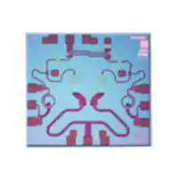
Analog Devices Inc. HMC-MDB218
- Part No.:
- HMC-MDB218
- Manufacturer:
- Analog Devices Inc.
- Category:
- RF Mixers
- Package:
- Die
- Datasheet:
-
 HMC-MDB218.pdf
- Description:
- IC MMIC IQ MIXER DIE
- Quantity:
- Payment:

- Shipping:

Inventory:3,556
Please send an inquiry. Send us your inquiry, and we will respond immediately.
Product details
Overview
HMC-MDB218 from Analog Devices is a GaAs MMIC sub-harmonically pumped image-reject mixer (IRM) operating at 54–64 GHz RF, 27–32 GHz LO, and DC–3 GHz IF, with 14 dB typical conversion loss, 30 dB image rejection, and no DC bias required-used in millimeter-wave SATCOM and radar front-ends.
For engineers reviewing the HMC-MDB218 datasheet, HMC-MDB218 pinout, HMC-MDB218 application, or HMC-MDB218 equivalent, key selection criteria include RF/LO frequency alignment, passive operation, die-level integration for hybrid MCMs, and quadrature hybrid–based image suppression in downconversion architectures.
Technical Context
The HMC-MDB218 implements a passive x2 sub-harmonic pumping architecture using GaAs HBT Schottky diode technology, enabling image rejection without active biasing. It requires an external 90° hybrid on the IF ports to select the desired sideband and achieve 30 dB measured image rejection.
Its RF and LO ports are DC-coupled and 50 Ω matched; IF1/IF2 ports are also DC-coupled and symmetric. All bond pads and backside metallization are Ti/Au, with fully passivated Schottky devices for reliability in hermetic hybrid assemblies.
Key Specifications
| Parameter | Value and Actual Design Meaning |
|---|---|
| RF Frequency Range | 54–64 GHz: Supports E-band short-haul radio and military radar bands. |
| LO Frequency Range | 27–32 GHz: Enables x2 sub-harmonic drive, halving LO source requirements. |
| IF Bandwidth | DC–3 GHz: Allows baseband-to-3 GHz signal processing without IF filtering constraints. |
| Conversion Loss | 14 dB typical: Defines RF-to-IF signal attenuation under +10 dBm LO drive at 1 GHz IF. |
| Image Rejection | 30 dB: Achieved with external 90° hybrid; enables single-sideband downconversion. |
| 1 dB Compression (Input) | –2 dBm: Sets maximum linear input power before gain compression in receiver chains. |
| IP3 (Input) | +7 dBm: Indicates third-order intermodulation performance in multi-tone environments. |
Pinout & Package
Package: Bare die, 1.54 × 1.41 × 0.1 mm, Ti/Au metallized bond pads and grounded backside; compatible with eutectic (AuSn) or conductive epoxy die attach and thermosonic wire bonding.
| Pin/Terminal | Circuit Role | Design Meaning |
|---|---|---|
| 1, 3 | IF1, IF2 | DC-coupled differential IF outputs requiring external 90° hybrid for image rejection. |
| 2 | RF | DC-coupled 50 Ω matched RF input/output port; primary signal path in up/downconversion. |
| 4 | LO | DC-coupled 50 Ω matched LO input port; accepts sub-harmonic drive at half RF frequency. |
Key Features
| Feature | Design Value |
|---|---|
| Passive Operation | No DC bias required-eliminates bias network complexity and leakage paths in mmWave layouts. |
| Sub-Harmonic Pumping (x2) | LO frequency is half RF band-reduces LO synthesis burden and phase noise impact at RF. |
| High Image Rejection | 30 dB achieved with standard 90° hybrid-enables clean SSB downconversion without image filter. |
| Millimeter-Wave Die Integration | 1.54 × 1.41 mm GaAs die with gold bond pads-optimized for MCM, hybrid, and waveguide-integrated front-ends. |
Applications
| Short-Haul Radios | SATCOM Terminals |
|---|---|
Use Scenario: High-capacity point-to-point wireless links in E-band (60 GHz unlicensed). IC Role / Device Role / Timing Role: Sub-harmonic IRM downconverter translating 57–64 GHz air interface to 0–3 GHz IF for digitization. Use Value: 30 dB image rejection enables full 7 GHz channel bandwidth without image filter insertion loss. | Use Scenario: Mobile satellite communication terminals requiring low-SWaP mmWave front-ends. IC Role / Device Role / Timing Role: Passive IRM in transmit/receive duplexed SATCOM transceivers operating at 54–64 GHz. Use Value: No DC bias simplifies power management; small die size supports compact phased-array antenna modules. |
| Military Radar Receivers | Test & Measurement Systems |
Use Scenario: EW/ECM systems detecting and characterizing hostile radar emissions in 54–64 GHz band. IC Role / Device Role / Timing Role: Image-reject front-end mixer in wideband digital IF receivers. Use Value: DC–3 GHz IF bandwidth supports real-time spectrum analysis of pulsed and chirped threats. | Use Scenario: Vector network analyzers and signal analyzers requiring calibrated mmWave mixing. IC Role / Device Role / Timing Role: Probed-die mixer for on-wafer characterization and calibration reference. Use Value: Measured performance referenced to 50 Ω environment ensures traceable S-parameter modeling. |
Equivalent & Alternatives
The following parts are listed as comparable options for similar sub-harmonic image-reject mixer applications.
| Alternative Part | Technical Difference | Application Difference | Selection Advice |
|---|---|---|---|
| HMC-MDB219 | Same die family; optimized for 60–70 GHz RF band (LO 30–35 GHz); 0.2 dB higher conversion loss. | Targeted at higher-frequency 60 GHz+ test equipment and next-gen radar; not interchangeable without LO redesign. | Select HMC-MDB219 only when extending coverage beyond 64 GHz. |
| HMC215MS8G | Active double-balanced mixer (GaAs pHEMT); requires +5 V bias; 5–12 GHz RF range; no sub-harmonic operation. | Used in lower-frequency IF/RF stages; incompatible LO architecture and frequency plan. | Consider only for non-sub-harmonic, bias-enabled designs below 12 GHz. |
Compared with HMC-MDB218, HMC-MDB219 extends upper RF frequency but increases LO demand, while HMC215MS8G offers active gain at lower frequencies but eliminates sub-harmonic advantage and adds bias complexity.
Availability
HMC-MDB218 is available at Aetrix Electronics and suitable for short-haul radios, SATCOM terminals, and military radar receivers requiring stable component supply across extended temperature ranges (–55 °C to +85 °C) and high-reliability hybrid assembly.
Supply support for HMC-MDB218 includes scheduled delivery planning, volume procurement assistance, BOM continuity management, traceable sourcing, and lifecycle availability coordination for OEM customers, industrial embedded developers, connected-device designers, and electronics production programs.
Manufacturer
Analog Devices, Inc. is a global leader in high-performance analog, mixed-signal, and RF ICs, serving communications, defense, instrumentation, and industrial markets since 1965.
The HMC-MDB218 belongs to Analog Devices' Hittite Microwave MMIC mixer product line, designed specifically for millimeter-wave sub-harmonic image-reject applications in defense and SATCOM systems.
FAQ
What is the recommended LO drive level for optimal performance of the HMC-MDB218?
The HMC-MDB218 achieves specified conversion loss and image rejection with +10 dBm LO drive at 27–32 GHz. Drive levels below +8 dBm increase conversion loss; above +12 dBm risk compression or degradation. Absolute maximum LO is 16 dBm-exceeding this may cause permanent damage. Always verify LO spectral purity, as phase noise directly impacts downconverted signal integrity in the HMC-MDB218.
Does the HMC-MDB218 require DC bias or external power?
No, the HMC-MDB218 is a fully passive GaAs MMIC mixer and requires no DC bias or external power supply. Its Schottky diode-based architecture operates solely on RF and LO signal energy. This eliminates bias networks, reduces thermal load, and simplifies layout in sensitive mmWave circuits-making the HMC-MDB218 ideal for low-power and high-density hybrid microcircuits where the HMC-MDB218 is deployed.
How is image rejection achieved with the HMC-MDB218?
Image rejection in the HMC-MDB218 is achieved externally using a 90° hybrid coupler connected to the IF1 and IF2 ports. The HMC-MDB218 itself provides inherent phase/amplitude balance (1° phase, 0.3 dB amplitude), enabling ≥30 dB image rejection when combined with a high-quality hybrid. Without the hybrid, the HMC-MDB218 functions as a standard double-balanced mixer-not an image-reject configuration.
What packaging options are available for the HMC-MDB218?
The HMC-MDB218 is supplied as a bare die in Gel Pack (GP-2) format per MIL-STD-883 Method 2010, Condition B. Alternate packaging is available upon request from Analog Devices. The die features Ti/Au metallization on all bond pads and grounded backside, supporting eutectic (AuSn) or conductive epoxy die attach and thermosonic wire bonding-standard practice for integrating the HMC-MDB218 into multichip modules and custom RF assemblies.
Can the HMC-MDB218 be used for upconversion as well as downconversion?
Yes, the HMC-MDB218 is bidirectional and supports both upconversion and downconversion. In upconversion mode, it functions as a single-sideband (SSB) upconverter when driven with quadrature IF signals and a sub-harmonic LO. Performance metrics-including conversion loss, IP3, and isolation-are specified under probed-die conditions and apply equally to both modes, provided matching networks and hybrid topology are adapted accordingly for the HMC-MDB218's intended use case.
HMC-MDB218 Specifications
- Product attributes
- Attribute value
- Manufacturer:
- Analog Devices Inc.
- Series:
- -
- Package/Case:
- Die
- Packaging:
- Bulk
- Product Status:
- Active
- RF Type:
- Radar
- Frequency:
- 54GHz ~ 64GHz
- Number of Mixers:
- 2
- Gain:
- -
- Noise Figure:
- -
- Secondary Attributes:
- Up Converter
- Current - Supply:
- -
- Voltage - Supply:
- -
- Mounting Type:
- Surface Mount
- Supplier Device Package:
- Die
HMC-MDB218 FAQ
1.How can I place an order for HMC-MDB218 through Aetrix?
Please submit a Request for Quotation (RFQ) for HMC-MDB218 on Aetrix. Our sales agent will provide a competitive quotation and guide you through the order confirmation once you accept the terms.
2.Are the price and stock information for HMC-MDB218 reliable?
The price and inventory of HMC-MDB218 are updated periodically and may fluctuate due to market conditions. Stock and pricing data are typically refreshed every 24 hours. Quotation validity for HMC-MDB218 is usually 5 days.
3.What payment methods are accepted for HMC-MDB218?
We accept Wire Transfer, PayPal, Credit Card, Western Union, MoneyGram, and Escrow for HMC-MDB218 transactions.
Note: Certain payment methods may incur a processing fee.
4.How is shipping managed for HMC-MDB218?
HMC-MDB218 orders can be shipped via leading logistics carriers, including DHL, UPS, FedEx, TNT, or Registered Mail.
Once your HMC-MDB218 order is processed, you will receive an email with the shipment details and tracking number.
Note: Tracking information may take up to 24 hours to appear. Express delivery typically takes 3–5 business days.
5.How can I obtain technical support or documentation for HMC-MDB218?
For technical support, including HMC-MDB218 datasheets, pinout diagrams, or application guidance, please contact our engineering support team. They can provide detailed documentation and assistance for your HMC-MDB218 requirements.
6.How does Aetrix verify that HMC-MDB218 is sourced from the original manufacturer or authorized distributors?
All HMC-MDB218 products on Aetrix are procured from qualified distributors and authorized channels. Our dedicated quality assurance team conducts strict verification, including traceability checks and, if necessary, third-party testing. This ensures that HMC-MDB218 meets industry standards.
7.What is the process for return or replacement of HMC-MDB218?
All HMC-MDB218 units undergo pre-shipment inspection (PSI). If there is an issue with HMC-MDB218, returns or replacements are accepted under the following conditions:
1.Quantity discrepancies, incorrect items, or visible external defects (such as breakage or corrosion), acknowledged by Aetrix.
2.The issue is reported within 90 days of delivery.
3.The HMC-MDB218 part is unused and in its original packaging.
Return procedure for HMC-MDB218:
1.Submit a request within 90 days.
2.Obtain a Return Material Authorization (RMA) from Aetrix.
HMC-MDB218 Tags
-
MAX2671EUT+T
Analog Devices Inc./Maxim Integrated

-
ADEX-10+
Mini-Circuits
-
ADE-2+
Mini-Circuits
-
ADE-1+
Mini-Circuits
-
LT5560EDD#PBF
Analog Devices Inc.
-
LT5560EDD#TRPBF
Analog Devices Inc.

-
LTC5562IUC#TRPBF
Analog Devices Inc.
-
MAX2681EUT+T
Analog Devices Inc./Maxim Integrated
-
ADE-1ASK+
Mini-Circuits
-
ADE-1L+
Mini-Circuits
-
ADL5350ACPZ-R7
Analog Devices Inc.
-
AD608ARZ-RL
Analog Devices Inc.
Tech Hub

A practical engineering guide to 3.3V and 5V logic compatibility, input thresholds, resistor dividers, translator ICs, MOSFET level shifting, I2C pull-ups, timing limits and power-sequencing risks.

The 74HC595 uses push-pull logic outputs, while the TPIC6B595 uses 50 V open-drain DMOS sinks for higher-power loads. This guide compares timing, current limits, 3.3 V interfacing, load wiring, thermal…

The 74HC595 converts serial data into eight stable parallel outputs. This guide covers pin functions, shift and storage timing, OE and MR behavior, drive-current limits, cascading, voltage compatibilit…

A technical comparison of level-sensitive latches and edge-triggered flip-flops, covering timing windows, setup and hold limits, master–slave operation, time borrowing, race-through, HDL inference and…

A D latch stores one bit while Enable controls when data can pass. This reference covers gate-level operation, truth tables, transparency, setup and hold timing, LE versus OE, common ICs and practical …

An SR latch stores one bit through cross-coupled feedback. This engineering reference covers NOR and NAND implementations, truth tables, forbidden-state recovery, gated operation, switch debouncing, fa…

Latch circuits retain one bit through feedback. This technical reference covers SR and D latches, truth tables, transparency, timing limits, latch-versus-flip-flop behavior, applications and common log…

An engineering guide to LED driver operation, constant-current and constant-voltage outputs, linear and switching topologies, dimming, IC selection, calculations, replacement compatibility, and fault c…

Operational amplifier guide covering op amp basics, feedback, ideal vs real op amps, common configurations, buffer circuits, offset, bias current, gain-bandwidth, slew rate, rail-to-rail limits and sel…

Jumper cables guide covering safe connection order, red and black clamp placement, final ground connection, cable gauge, length, clamp quality, copper vs CCA cables, jump starter comparison and battery…


