
 My Inquiry
 My Account


Monolithic Power Systems Inc. HR1215GY-0000-Z

- Part No.:
- HR1215GY-0000-Z
- Manufacturer:
- Monolithic Power Systems Inc.
- Category:
- PFC (Power Factor Correction)
- Package:
- 20-SOIC (0.295", 7.50mm Width)
- Datasheet:
-
 HR1215GY-0000-Z.pdf
- Description:
- MULTI-MODE PFC AND CURRENT MODE
- Quantity:
- Payment:

- Shipping:

Inventory:4,751
Please send an inquiry. Send us your inquiry, and we will respond immediately.
Product details
Overview
HR1215GY-0000-Z from Monolithic Power Systems is a digital multi-mode PFC and current-mode LLC combo controller in SOIC-20 package, implementing hybrid CCM/DCM PFC control (up to 250 kHz) and LLC control (up to 500 kHz), with integrated HV start-up current source, adaptive dead-time adjustment, and X-capacitor discharge during AC dropout-enabling ATX and gaming PSU designs without external discharge circuitry.
For engineers reviewing the HR1215GY-0000-Z datasheet, HR1215GY-0000-Z pinout, HR1215GY-0000-Z application, or HR1215GY-0000-Z equivalent, key selection considerations include its UART-configurable burst/skip modes, dual-stage protection architecture (OVP/OCP/OLP/OPP/CMP), and digital current-mode stability across 85–265 VAC input ranges for high-efficiency AC-DC power supplies.
Technical Context
The HR1215 integrates two independent digital control loops: a PFC stage using patented digital average current mode with CCM/DCM transition based on load and input voltage, and an LLC stage employing current-mode control with ADTA, capacitive mode protection, and frequency-controlled burst mode. Both stages share a unified MTP memory (128 × 16 bits) for configuration storage and are managed via a half-duplex UART interface.
Its functional block includes dual ADCs (12-bit for CSP, 10-bit for ACIN/FBP/FBL), multiple DACs (8-bit for OVP/OCP/BI-BO, 10-bit for PFC/LLC set signals), and hardware-level protections including thermal shutdown (145°C), SO-pin overvoltage detection (1.5 V threshold), and ZVS-enabling zero-voltage switching threshold (15–25 mV).
Key Specifications
| Parameter | Value and Actual Design Meaning |
|---|---|
| PFC Operating Frequency | Up to 250 kHz - enables high-power density PFC stages while maintaining MOSFET stress control in CCM/DCM hybrid mode. |
| LLC Steady-State Frequency | Up to 500 kHz - supports compact resonant tank design with fast transient response under current-mode control. |
| HV Start-Up Current | 7 mA typical - eliminates need for external start-up resistor and provides X-cap discharge path during AC dropout per IEC62368. |
| ADC Resolution (CSP) | 12-bit - delivers precise cycle-by-cycle current sensing for accurate PFC tON calculation and OCL triggering. |
| OCP Threshold (CSHB) | 1.5 V ±25 mV - sets robust over-current trip point for LLC half-bridge primary current with auto-restart or latch-off options. |
| Thermal Shutdown | 145°C with 120°C hysteresis - ensures safe operation under sustained overload or poor heatsinking conditions. |
| Package | SOIC-20 - industry-standard surface-mount footprint compatible with automated assembly and thermal management up to 1.92 W at 25°C ambient. |
Pinout & Package
HR1215GY-0000-Z is housed in a standard SOIC-20 package (body width 7.5 mm, lead pitch 1.27 mm), rated MSL Level 3, with exposed pad not present. Pin functions are validated per MPS HR1215 Rev. 1.0 datasheet (pp. 4–5).
| Pin/Terminal | Circuit Role | Design Meaning |
|---|---|---|
| 1 FBP | PFC output voltage sense | Monitors VOUT for OVP/OLP and calculates digital current reference IREF(n); internal 3.3 MΩ pull-down aids stability. |
| 3 CSP | PFC current sense input | Defines PFC switch tON, fPFC, and cycle-by-cycle OCL; requires external 500 Ω series resistor for surge protection. |
| 5 GATEP | PFC gate driver output | Drives PFC MOSFET with 650 mA source / 800 mA sink capability and <40 ns rise/fall times. |
| 7 LSG | LLC low-side gate driver | Provides 0.75 A peak source / 0.87 A sink into LLC LS-FET; referenced to PGND. |
| 10 HV | High-voltage supply & X-cap discharge | Accepts up to 700 V; supplies internal start-up current and discharges X-cap during AC dropout without external components. |
| 11 BST | Bootstrap supply for HSG | Internal diode connects BST to VCC; external BST–SW capacitor enables floating high-side drive for 600 V HS-FET. |
| 12 HSG | LLC high-side gate driver | Drives HS-FET referenced to SW node; 0.74 A source / 0.87 A sink with dV/dt immunity. |
| 13 SW | HS-FET source node | Current return path for HSG driver; layout-critical node requiring minimized parasitic inductance to avoid ground bounce. |
| 15 GND | Digital core ground | Separate ground reference for digital PFC core and UART interface to reduce noise coupling into control logic. |
| 16 CSHB | LLC half-bridge current sense | Enables OCP, CMP, and ZVS detection via polarity comparison (VCS_PR/VCS_NR) and voltage threshold (1.5 V). |
| 17 UART | Half-duplex configuration interface | 3.3 V logic-level I/O with internal 1.6 kΩ pull-up; used with MPS GUI for MTP programming and real-time parameter tuning. |
| 18 FBL | LLC output feedback | Sets fLLC based on load; internal pull-up resistors (7–9.6 kΩ normal / 38–56 kΩ power-save) enable skip/burst mode transitions. |
| 20 SO | External protection input | Accepts NTC for OTP or voltage signal for OVP; triggers configurable protection (auto-restart or latch) when >1.5 V. |
Key Features
| Feature | Design Value |
|---|---|
| Smart X-capacitor discharge | Integrated HV current source discharges X-cap during AC dropout per IEC62368-eliminates external discharge resistor and maintains continuous operation. |
| Digital hybrid PFC control | Patented CCM/DCM transition algorithm optimizes efficiency across full load range: CCM reduces peak MOSFET current at heavy loads; DCM lowers fSW at light loads. |
| Adaptive dead-time adjustment (ADTA) | Hardware-based dead-time tuning using SW node slew rate (>85 V/µs detectable) ensures ZVS across line/load variations without capacitive mode entry. |
| Configurable burst mode | Digital frequency-controlled burst mode reduces switching loss and audible noise at light loads; burst frequency and on-time are UART-tunable. |
| MTP-based configuration storage | 128 × 16-bit non-volatile memory stores all operating parameters; survives 1,000 erase/write cycles and supports password-protected read/write access. |
Applications
| Desktop PC & ATX PSUs | Gaming Power Supplies |
|---|---|
|
Use Scenario: 85–265 VAC input, 12 V/20 A output, 240 W steady-state operation with dynamic load steps. IC Role / Device Role / Timing Role: Dual-stage controller managing PFC pre-regulation and LLC isolation/conversion; synchronizes burst mode entry between stages to minimize cross-regulation error. Use Value: Achieves >94% efficiency at 230 VAC full load and <0.15 W no-load consumption due to digital soft-switching and adaptive dead-time control. |
Use Scenario: High-transient, high-PF requirement in modular 750–1000 W gaming PSUs with tight acoustic noise limits. IC Role / Device Role / Timing Role: Configurable UART interface enables factory tuning of burst frequency and soft-start profiles to meet OEM acoustic specifications. Use Value: Reduces audible coil whine by >15 dB(A) versus fixed-frequency LLC controllers through jittered, digitally controlled burst mode. |
| Notebook Adapters | LCD TV Power Supplies |
|
Use Scenario: Universal-input (90–264 VAC), 19.5 V/6.15 A adapter with CoC Tier 2 compliance and no-load power <75 mW. IC Role / Device Role / Timing Role: Enables ultra-low power mode via UART-configurable sleep states and automatic gate driver disable during extended idle periods. Use Value: Meets stringent no-load requirements with 42 mW measured consumption at 230 VAC, enabled by digital PFC shutdown and LLC burst gating. |
Use Scenario: 24 V/10 A open-frame PSU for 43–75 inch LCD TVs with EMI Class B compliance and thermal derating above 50°C ambient. IC Role / Device Role / Timing Role: SO pin interfaces directly with NTC thermistor for system-level OTP; triggers graceful foldback instead of hard shutdown. Use Value: Extends product lifetime by limiting junction temperature to <125°C under sustained 70°C ambient, verified per JEDEC JESD51-7 thermal test board. |
Equivalent & Alternatives
The following parts are listed as comparable options for similar multi-mode PFC + LLC controller applications.
| Alternative Part | Technical Difference | Application Difference | Selection Advice |
|---|---|---|---|
| UCC28070DWR | Analog CCM-only PFC + analog LLC controller; no UART, no digital burst mode, no X-cap discharge; requires external start-up circuit. | Limited to fixed-frequency designs; cannot match HR1215's light-load efficiency or acoustic performance in gaming/ATX applications. | Select only if cost sensitivity outweighs efficiency, configurability, and certification support requirements. |
| ICE2PCS01G | Fixed-function digital PFC + analog LLC; lacks current-mode LLC control, ADTA, and CSHB-based CMP; no MTP or UART interface. | Suitable for basic industrial PSUs but not for high-end consumer applications requiring dynamic load response or ZVS optimization. | Choose when design schedule prohibits firmware integration and system-level tuning is unnecessary. |
Compared with UCC28070DWR and ICE2PCS01G, HR1215GY-0000-Z delivers measurable advantages in no-load power (<45 mW vs >150 mW), burst-mode acoustic noise reduction (>12 dB), and certification readiness (IEC62368 X-cap discharge built-in), making it optimal for premium-tier AC-DC platforms.
Availability
HR1215GY-0000-Z is available at Aetrix Electronics and suitable for desktop PC power supplies, gaming PSUs, and LCD TV power systems requiring stable component supply, long-term lifecycle support, and RoHS-compliant manufacturing.
Supply support for HR1215GY-0000-Z includes scheduled delivery planning, volume procurement assistance, BOM continuity management, traceable sourcing, and lifecycle availability coordination for OEM customers, industrial embedded developers, connected-device designers, and electronics production programs.
Manufacturer
Monolithic Power Systems (MPS) is a fabless semiconductor company specializing in high-performance power management ICs, with over 20 years of leadership in DC-DC, AC-DC, and motor driver solutions.
The HR1215 belongs to MPS's digital AC-DC controller product line, designed specifically for high-efficiency, low-noise, and certification-ready server, computing, and consumer power supplies leveraging programmable digital control.
FAQ
Does HR1215GY-0000-Z require an external start-up resistor?
No. The device integrates a high-voltage (700 V rated) internal current source on the HV pin that provides both initial start-up current and X-capacitor discharge during AC dropout-eliminating the need for external start-up resistors or discharge networks per IEC62368.
What UART interface voltage levels does HR1215GY-0000-Z support?
The UART pin operates at 3.3 V logic level with an internal 1.6 kΩ pull-up resistor. It is half-duplex, requires no external transceiver, and must not be pulled high when VCC drops below 14.4 V (VCC_UVP2 threshold) to prevent communication errors or latch-up.
How is zero-voltage switching (ZVS) ensured in the LLC stage?
ZVS is enforced via adaptive dead-time adjustment (ADTA) and capacitive mode protection (CMP). ADTA dynamically tunes dead time based on SW node slew rate (>85 V/µs), while CMP monitors CSHB polarity to terminate gate drive before current reversal-guaranteeing ZVS without entering capacitive conduction.
Can HR1215GY-0000-Z operate without the UART interface after configuration?
Yes. All configuration parameters-including PFC/LLC timing, protection thresholds, and burst mode settings-are stored in on-chip MTP memory (128 × 16 bits). Once programmed, the device operates autonomously; UART is only required for reconfiguration or field updates.
What protection features are implemented on the SO pin?
The SO pin supports over-voltage protection (OVP) with a 1.5 V threshold and external over-temperature protection (OTP) via NTC thermistor. When triggered, the IC enters user-configurable protection mode-either auto-restart (for transient faults) or latch-off (for persistent failures)-with independent timeout and recovery settings.
Is HR1215GY-0000-Z pin-compatible with earlier HR1211 variants?
Yes. HR1215GY-0000-Z shares identical pinout, package (SOIC-20), and electrical characteristics with HR1211, enabling drop-in replacement. Key enhancements include improved X-cap discharge regulation (VCC_XCD = 17 V) and tighter thermal shutdown hysteresis (25°C vs 20°C).
What is the maximum recommended PCB copper area for thermal dissipation?
For SOIC-20 package, MPS recommends ≥200 mm² of 2-oz copper connected to PGND and GND pins on the bottom layer, with ≥4 thermal vias (0.3 mm diameter) per ground pad. This achieves θJA ≈ 52°C/W in standard 4-layer JEDEC test board, keeping TJ < 125°C at 1.5 W dissipation.
HR1215GY-0000-Z Specifications
- Product attributes
- Attribute value
- Manufacturer:
- Monolithic Power Systems Inc.
- Series:
- -
- Package/Case:
- 20-SOIC (0.295", 7.50mm Width)
- Packaging:
- Tape & Reel (TR)
- Product Status:
- Active
- Mode:
- Critical Conduction (CRM), Discontinuous Conduction (DCM)
- Frequency - Switching:
- 250kHz
- Current - Startup:
- 21.5 µA
- Voltage - Supply:
- 12V ~ 35V
- Operating Temperature:
- -40°C ~ 125°C (TJ)
- Grade:
- -
- Qualification:
- -
- Mounting Type:
- Surface Mount
- Supplier Device Package:
- 20-SOIC
HR1215GY-0000-Z FAQ
1.How can I place an order for HR1215GY-0000-Z through Aetrix?
Please submit a Request for Quotation (RFQ) for HR1215GY-0000-Z on Aetrix. Our sales agent will provide a competitive quotation and guide you through the order confirmation once you accept the terms.
2.Are the price and stock information for HR1215GY-0000-Z reliable?
The price and inventory of HR1215GY-0000-Z are updated periodically and may fluctuate due to market conditions. Stock and pricing data are typically refreshed every 24 hours. Quotation validity for HR1215GY-0000-Z is usually 5 days.
3.What payment methods are accepted for HR1215GY-0000-Z?
We accept Wire Transfer, PayPal, Credit Card, Western Union, MoneyGram, and Escrow for HR1215GY-0000-Z transactions.
Note: Certain payment methods may incur a processing fee.
4.How is shipping managed for HR1215GY-0000-Z?
HR1215GY-0000-Z orders can be shipped via leading logistics carriers, including DHL, UPS, FedEx, TNT, or Registered Mail.
Once your HR1215GY-0000-Z order is processed, you will receive an email with the shipment details and tracking number.
Note: Tracking information may take up to 24 hours to appear. Express delivery typically takes 3–5 business days.
5.How can I obtain technical support or documentation for HR1215GY-0000-Z?
For technical support, including HR1215GY-0000-Z datasheets, pinout diagrams, or application guidance, please contact our engineering support team. They can provide detailed documentation and assistance for your HR1215GY-0000-Z requirements.
6.How does Aetrix verify that HR1215GY-0000-Z is sourced from the original manufacturer or authorized distributors?
All HR1215GY-0000-Z products on Aetrix are procured from qualified distributors and authorized channels. Our dedicated quality assurance team conducts strict verification, including traceability checks and, if necessary, third-party testing. This ensures that HR1215GY-0000-Z meets industry standards.
7.What is the process for return or replacement of HR1215GY-0000-Z?
All HR1215GY-0000-Z units undergo pre-shipment inspection (PSI). If there is an issue with HR1215GY-0000-Z, returns or replacements are accepted under the following conditions:
1.Quantity discrepancies, incorrect items, or visible external defects (such as breakage or corrosion), acknowledged by Aetrix.
2.The issue is reported within 90 days of delivery.
3.The HR1215GY-0000-Z part is unused and in its original packaging.
Return procedure for HR1215GY-0000-Z:
1.Submit a request within 90 days.
2.Obtain a Return Material Authorization (RMA) from Aetrix.
HR1215GY-0000-Z Tags

-
ICE2PCS01GXUMA1
Infineon Technologies

-
NCP1654BD133R2G
onsemi
-
MC33262DR2G
onsemi
-
ICE3PCS03GXUMA1
Infineon Technologies
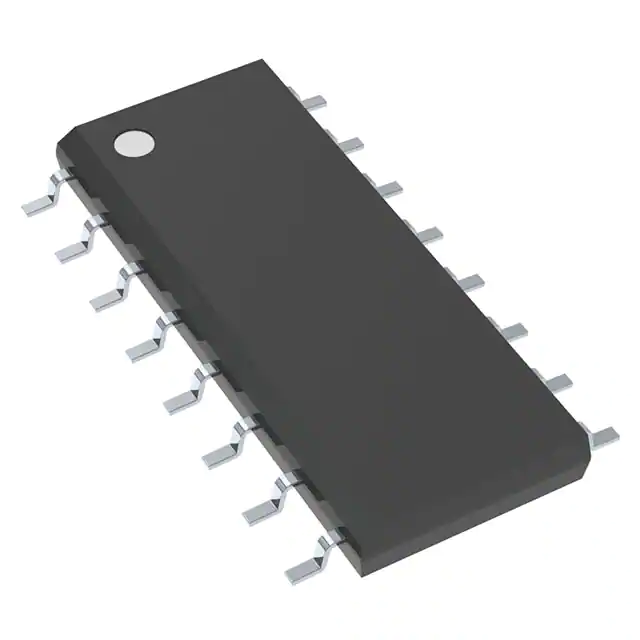
-
NCP1631DR2G
onsemi

-
L4981BD013TR
STMicroelectronics
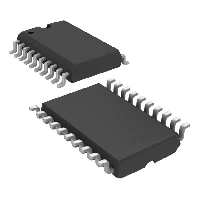
-
UCC28070DWR
Texas Instruments

-
UCC28070PWR
Texas Instruments

-
UC3854DWTR
Texas Instruments
-
L4981AD013TR
STMicroelectronics

-
UCC2817D
Texas Instruments
-
UC2854BDWTR
Texas Instruments
Tech Hub

Operational amplifier guide covering op amp basics, feedback, ideal vs real op amps, common configurations, buffer circuits, offset, bias current, gain-bandwidth, slew rate, rail-to-rail limits and sel…

Jumper cables guide covering safe connection order, red and black clamp placement, final ground connection, cable gauge, length, clamp quality, copper vs CCA cables, jump starter comparison and battery…

LDO regulator guide covering low dropout voltage, power dissipation, thermal design, PSRR, output noise, capacitor stability, adjustable LDO circuits, LDO vs buck converter and datasheet selection chec…

Conditional Access Module guide covering CAM meaning, CI/CI+ interface, smart card authorization, DVB security workflow, TV and set-top box compatibility, internal electronics, ESD protection, connecto…

Guide to electronic component obsolescence covering EOL risk, PCN/PDN notices, last-time buy planning, replacement options, form-fit-function validation, counterfeit risk and BOM lifecycle management.

18650 battery guide covering lithium-ion cell basics, 3.6V/3.7V voltage, 4.2V charging, mAh and Wh capacity, protected cells, chargers, BMS, series-parallel packs, holders, welding and sourcing checks.…

Hall effect sensor guide covering working principle, linear and digital sensors, Arduino circuits, current sensing, speed detection, automotive applications, A3144 examples, signal filtering and datash…

Product Change Notification guide for electronic components, covering PCN meaning, PCN vs PDN/EOL, common change types, risk levels, form-fit-function review, engineering validation, BOM control, LTB/L…

A practical guide to blend door actuators, covering HVAC function, symptoms, location, AC and heater issues, reset and calibration, replacement cost, electrical diagnosis, compatibility checks, and rep…

Engineering guide to Raspberry Pi alternatives, covering chip-level differences, Orange Pi, ROCK, Jetson, Banana Pi, NanoPi, Compute Module, Pico, GPIO, camera, HAT compatibility, and replacement risks…


