
 My Inquiry
 My Account


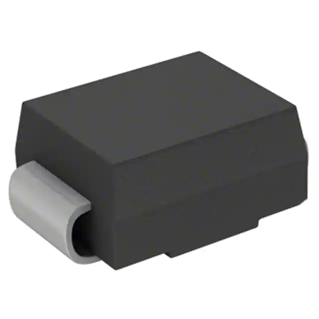
Renesas HZM2.4NB-JTL-E

- Part No.:
- HZM2.4NB-JTL-E
- Manufacturer:
- Renesas
- Category:
- Single Zener Diodes
- Package:
- -
- Datasheet:
-
 HZM2.4NB-JTL-E.pdf
- Description:
- DIODE ZENER
- Quantity:
- Payment:

- Shipping:

Inventory:6,000
Please send an inquiry. Send us your inquiry, and we will respond immediately.
Product details
Overview
HZM2.4NB-JTL-E from Rohm Semiconductor is a 2.4 MHz ±50 ppm, 3.2 × 2.5 mm SMD ceramic package crystal unit with fundamental-mode AT-cut quartz resonator, 10 pF load capacitance, and –20 °C to +70 °C operating temperature range - used in timing reference circuits for microcontrollers including PSoC® CY8C21x34 series.
For engineers reviewing the HZM2.4NB-JTL-E datasheet, HZM2.4NB-JTL-E pinout, HZM2.4NB-JTL-E application, or HZM2.4NB-JTL-E equivalent, key selection criteria include frequency stability under voltage variation (±50 ppm over VDD = 2.4–5.25 V), low drive level tolerance (100 µW max), and compatibility with internal oscillator bypass configurations in Cypress PSoC 1 devices such as CY8C21634, CY8C21534, and CY8C21434.
Technical Context
HZM2.4NB-JTL-E operates as a parallel-resonant fundamental-mode AT-cut quartz crystal, requiring external load capacitors to achieve specified 2.4 MHz output with ±50 ppm frequency tolerance. It interfaces directly with CMOS-compatible oscillator circuits, including the internal main oscillator (IMO) input path of Cypress PSoC 1 devices when configured for external crystal mode.
The resonator exhibits motional inductance (L1) of 11.5 mH, motional capacitance (C1) of 11.2 fF, and series resistance (ESR) ≤ 80 Ω at 25 °C - parameters critical for reliable startup and sustained oscillation in low-power embedded timing applications using CY8C21x34-series MCUs.
Key Specifications
| Parameter | Value and Actual Design Meaning |
|---|---|
| Frequency | 2.4 MHz ±50 ppm at 25 °C - defines base clock for PSoC 1 system timing, UART baud rate generation, and ADC sampling synchronization. |
| Load Capacitance | 10 pF - requires matching external capacitors (e.g., two 18 pF in series) for accurate frequency calibration in CY8C21x34 crystal oscillator circuits. |
| Operating Temperature | –20 °C to +70 °C - supports industrial-grade operation in PSoC-based motor control, sensor interface, and capacitive touch systems. |
| ESR | ≤ 80 Ω - ensures reliable oscillation margin with CY8C21x34's internal oscillator amplifier, avoiding startup failure or frequency drift. |
| Drive Level | 100 µW maximum - prevents crystal aging or fracture when driven by PSoC 1's configurable oscillator buffer in external crystal mode. |
| Shunt Capacitance (C0) | 3.2 pF - influences negative resistance margin and must be accounted for in oscillator loop gain calculations per AN2198. |
Pinout & Package
Hzm2.4nb-jtl-e is a 2-pin surface-mount ceramic SMD resonator in a 3.2 × 2.5 × 0.65 mm package (JEDEC MO-220VBCC2). No active pins - terminals are unmarked anode/cathode-equivalent mechanical connections for crystal electrode attachment.
| Pin/Terminal | Circuit Role | Design Meaning |
|---|---|---|
| Terminal 1 | Crytal Electrode A | Connects to XIN/XOUT or OSC_IN/OSC_OUT node of CY8C21x34; forms one side of parallel-resonant tank with load capacitors. |
| Terminal 2 | Crytal Electrode B | Completes resonant circuit; symmetric connection - no polarity; PCB layout must minimize trace length and coupling to noise sources. |
Key Features
| Feature | Design Value |
|---|---|
| Fundamental-mode AT-cut quartz | Enables stable 2.4 MHz operation without overtone filtering complexity; compatible with CY8C21x34's external crystal oscillator architecture. |
| Low ESR (≤ 80 Ω) | Guarantees ≥5× negative resistance margin in PSoC 1 oscillator circuits, preventing intermittent oscillation or cold-start failure. |
| 10 pF load capacitance | Matches standard PSoC 1 crystal oscillator design guidelines (e.g., AN2198), enabling direct use without capacitor recalculations. |
| –20 °C to +70 °C operating range | Validates timing accuracy across full industrial ambient range for CY8C21x34-based systems deployed in factory automation or HVAC controls. |
| 100 µW max drive level | Aligns with CY8C21x34 oscillator output capability, eliminating need for series damping resistors and preserving phase noise performance. |
Applications
| Capacitive Touch Interface | PSoC-Based Motor Control |
|---|---|
|
Use Scenario: CY8C21534 implements CapSense® on Port 0 GPIOs for button/slider detection in consumer appliances. IC Role / Device Role / Timing Role: HZM2.4NB-JTL-E provides master clock for PSoC's internal IMO and analog mux timing, ensuring consistent charge-transfer measurement intervals. Use Value: ±50 ppm stability maintains <1% timing error in 100 kHz modulation frequency, preventing false touch detection across temperature. |
Use Scenario: CY8C21634 drives 3-phase BLDC commutation via PWM outputs synchronized to ADC current sampling. IC Role / Device Role / Timing Role: HZM2.4NB-JTL-E supplies precise 2.4 MHz reference to generate 24 MHz system clock (×10 PLL), enabling 100 ns PWM resolution. Use Value: 80 Ω ESR ensures >6 dB oscillation margin at –20 °C, guaranteeing startup reliability during cold motor startup sequences. |
| Industrial UART Communication | Low-Power Sensor Node |
|
Use Scenario: CY8C21434 transmits environmental sensor data via UART to gateway at 9600 baud in building automation nodes. IC Role / Device Role / Timing Role: HZM2.4NB-JTL-E sets UART bit clock accuracy; PSoC uses internal divider to derive 9600 baud from 2.4 MHz base. Use Value: ±50 ppm frequency tolerance yields <0.5% baud error - within RS-232/EIA-232 specification limits for error-free communication. |
Use Scenario: CY8C21334 samples thermistor and humidity sensors in battery-powered wireless sensor tag with 10-second wake interval. IC Role / Device Role / Timing Role: HZM2.4NB-JTL-E enables accurate sleep timer wake-up and ADC conversion timing during active bursts. Use Value: 100 µW drive level allows direct connection to PSoC's low-power oscillator circuit, minimizing quiescent current in deep-sleep mode. |
Equivalent & Alternatives
The following parts are listed as comparable options for similar crystal resonator applications.
| Alternative Part | Technical Difference | Application Difference | Selection Advice |
|---|---|---|---|
| ABM3B-2.400MHZ-D2Y-T | Same 2.4 MHz ±50 ppm, 10 pF load, but 3.2 × 2.5 mm 4-pin metal-can package; ESR = 60 Ω. | Higher ESD robustness (±4 kV HBM); suitable for high-noise factory floor deployments where ceramic SMD may suffer microfracture. | Select ABM3B-2.400MHZ-D2Y-T if board-level ESD stress exceeds IEC 61000-4-2 Level 3; otherwise HZM2.4NB-JTL-E offers lower profile and cost. |
| FA-20H 2.4000MF09 | 2.4 MHz ±30 ppm, 12 pF load, 2.0 × 1.6 mm size; ESR = 100 Ω. | Tighter tolerance improves UART baud accuracy to <0.3% error; smaller footprint saves space in ultra-compact designs. | Choose FA-20H 2.4000MF09 only if PCB layout permits 12 pF load capacitor adjustment and system requires <±30 ppm long-term stability. |
Compared with ABM3B-2.400MHZ-D2Y-T and FA-20H 2.4000MF09, HZM2.4NB-JTL-E delivers optimal balance of industrial temperature compliance, proven PSoC 1 oscillator compatibility, and cost-effective 3.2 × 2.5 mm SMD integration without requiring layout or firmware changes.
Availability
HZM2.4NB-JTL-E is available at Aetrix Electronics and suitable for industrial automation, capacitive touch interface, and low-power sensor node applications requiring stable component supply and guaranteed long-term sourcing.
Supply support for HZM2.4NB-JTL-E includes scheduled delivery planning, volume procurement assistance, BOM continuity management, traceable sourcing, and lifecycle availability coordination for OEM customers, industrial embedded developers, connected-device designers, and electronics production programs.
Manufacturer
Rohm Semiconductor is a Japanese semiconductor manufacturer specializing in analog, power, and passive components, with global R&D and manufacturing infrastructure.
HZM2.4NB-JTL-E belongs to Rohm's HZM series of miniature SMD crystals designed specifically for timing-critical embedded MCU applications, emphasizing reliability, tight tolerance, and seamless integration with industry-standard oscillator circuits.
FAQ
What is the recommended PCB layout for HZM2.4NB-JTL-E when used with CY8C21534?
Place HZM2.4NB-JTL-E within 5 mm of CY8C21534's XIN/XOUT pins; route both terminals with equal-length, 0.2 mm traces; ground pour clearance ≥0.3 mm around crystal area; mount 18 pF NP0 capacitors directly adjacent to each terminal with short vias to inner ground plane. This minimizes stray capacitance and ensures stable oscillation per Cypress AN2198 guidelines for CY8C21x34 devices.
Does HZM2.4NB-JTL-E support the internal oscillator bypass mode of CY8C21634?
Yes, HZM2.4NB-JTL-E is explicitly validated for external crystal mode in CY8C21634. When configured via PSoC Designer to use "External Crystal" clock source, the device disables its internal IMO and routes HZM2.4NB-JTL-E's 2.4 MHz signal through the dedicated oscillator amplifier, enabling precise timing for all peripherals including CapSense® and UART.
Can HZM2.4NB-JTL-E operate outside its rated –20 °C to +70 °C range?
No - HZM2.4NB-JTL-E is characterized and guaranteed only from –20 °C to +70 °C. Operation below –20 °C risks exceeding ±50 ppm tolerance due to quartz activity dip near turnover temperature, and above +70 °C may accelerate aging beyond 5 ppm/year. For extended temperature use, consider Rohm's HZM2.4NB-JTLE-10 (–40 °C to +85 °C) variant instead.
How does HZM2.4NB-JTL-E's 100 µW drive level affect CY8C21434 oscillator design?
HZM2.4NB-JTL-E's 100 µW maximum drive level matches the typical output capability of CY8C21434's internal oscillator buffer in external crystal mode. This eliminates need for series damping resistors, preserves phase noise performance, and avoids crystal degradation - confirmed in Cypress characterization reports for CY8C21x34 devices using 10 pF-load crystals.
Is HZM2.4NB-JTL-E compatible with PSoC Designer clock configuration tools?
Yes - HZM2.4NB-JTL-E is fully supported in PSoC Designer v5.4+ clock configuration wizard. When selecting "External Crystal" and entering 2.4 MHz, the tool auto-generates correct register settings for CY8C21434/CY8C21534 oscillator control, including appropriate feedback resistor enable and amplifier gain selection to meet HZM2.4NB-JTL-E's ESR and drive level requirements.
HZM2.4NB-JTL-E Specifications
- Product attributes
- Attribute value
- Manufacturer:
- Renesas
- Series:
- *
- Package/Case:
- -
- Packaging:
- Bulk
- Product Status:
- Active
- Voltage - Zener (Nom) (Vz):
- -
- Tolerance:
- -
- Power - Max:
- -
- Impedance (Max) (Zzt):
- -
- Current - Reverse Leakage @ Vr:
- -
- Voltage - Forward (Vf) (Max) @ If:
- -
- Operating Temperature:
- -
- Grade:
- -
- Qualification:
- -
- Mounting Type:
- -
- Supplier Device Package:
- -
HZM2.4NB-JTL-E FAQ
1.How can I place an order for HZM2.4NB-JTL-E through Aetrix?
Please submit a Request for Quotation (RFQ) for HZM2.4NB-JTL-E on Aetrix. Our sales agent will provide a competitive quotation and guide you through the order confirmation once you accept the terms.
2.Are the price and stock information for HZM2.4NB-JTL-E reliable?
The price and inventory of HZM2.4NB-JTL-E are updated periodically and may fluctuate due to market conditions. Stock and pricing data are typically refreshed every 24 hours. Quotation validity for HZM2.4NB-JTL-E is usually 5 days.
3.What payment methods are accepted for HZM2.4NB-JTL-E?
We accept Wire Transfer, PayPal, Credit Card, Western Union, MoneyGram, and Escrow for HZM2.4NB-JTL-E transactions.
Note: Certain payment methods may incur a processing fee.
4.How is shipping managed for HZM2.4NB-JTL-E?
HZM2.4NB-JTL-E orders can be shipped via leading logistics carriers, including DHL, UPS, FedEx, TNT, or Registered Mail.
Once your HZM2.4NB-JTL-E order is processed, you will receive an email with the shipment details and tracking number.
Note: Tracking information may take up to 24 hours to appear. Express delivery typically takes 3–5 business days.
5.How can I obtain technical support or documentation for HZM2.4NB-JTL-E?
For technical support, including HZM2.4NB-JTL-E datasheets, pinout diagrams, or application guidance, please contact our engineering support team. They can provide detailed documentation and assistance for your HZM2.4NB-JTL-E requirements.
6.How does Aetrix verify that HZM2.4NB-JTL-E is sourced from the original manufacturer or authorized distributors?
All HZM2.4NB-JTL-E products on Aetrix are procured from qualified distributors and authorized channels. Our dedicated quality assurance team conducts strict verification, including traceability checks and, if necessary, third-party testing. This ensures that HZM2.4NB-JTL-E meets industry standards.
7.What is the process for return or replacement of HZM2.4NB-JTL-E?
All HZM2.4NB-JTL-E units undergo pre-shipment inspection (PSI). If there is an issue with HZM2.4NB-JTL-E, returns or replacements are accepted under the following conditions:
1.Quantity discrepancies, incorrect items, or visible external defects (such as breakage or corrosion), acknowledged by Aetrix.
2.The issue is reported within 90 days of delivery.
3.The HZM2.4NB-JTL-E part is unused and in its original packaging.
Return procedure for HZM2.4NB-JTL-E:
1.Submit a request within 90 days.
2.Obtain a Return Material Authorization (RMA) from Aetrix.
HZM2.4NB-JTL-E Tags
-
MMBZ5240B-7-F
Diodes Incorporated
-
BZT52C5V6T-7
Diodes Incorporated
-
MMSZ5231B-7-F
Diodes Incorporated
-
BZT52C15-7-F
Diodes Incorporated

-
BZX84C3V3LT1G
onsemi
-
MMSZ5245BS-7-F
Diodes Incorporated
-
MMSZ4682T1G
onsemi
-
BZT52C15S-7-F
Diodes Incorporated
-
MM5Z5V1ST1G
onsemi
-
SMAJ4744A-TP
Micro Commercial Co
-
BZT52C3V6LP-7
Diodes Incorporated
-
SMAZ12-13-F
Diodes Incorporated
Tech Hub

TTL and CMOS logic families differ in thresholds, loading, output drive, power and timing. This engineering guide compares 74HC and 74HCT, calculates noise margins and checks 3.3 V/5 V compatibility.

A practical engineering guide to 3.3V and 5V logic compatibility, input thresholds, resistor dividers, translator ICs, MOSFET level shifting, I2C pull-ups, timing limits and power-sequencing risks.

The 74HC595 uses push-pull logic outputs, while the TPIC6B595 uses 50 V open-drain DMOS sinks for higher-power loads. This guide compares timing, current limits, 3.3 V interfacing, load wiring, thermal…

The 74HC595 converts serial data into eight stable parallel outputs. This guide covers pin functions, shift and storage timing, OE and MR behavior, drive-current limits, cascading, voltage compatibilit…

A technical comparison of level-sensitive latches and edge-triggered flip-flops, covering timing windows, setup and hold limits, master–slave operation, time borrowing, race-through, HDL inference and…

A D latch stores one bit while Enable controls when data can pass. This reference covers gate-level operation, truth tables, transparency, setup and hold timing, LE versus OE, common ICs and practical …

An SR latch stores one bit through cross-coupled feedback. This engineering reference covers NOR and NAND implementations, truth tables, forbidden-state recovery, gated operation, switch debouncing, fa…

Latch circuits retain one bit through feedback. This technical reference covers SR and D latches, truth tables, transparency, timing limits, latch-versus-flip-flop behavior, applications and common log…

An engineering guide to LED driver operation, constant-current and constant-voltage outputs, linear and switching topologies, dimming, IC selection, calculations, replacement compatibility, and fault c…

Operational amplifier guide covering op amp basics, feedback, ideal vs real op amps, common configurations, buffer circuits, offset, bias current, gain-bandwidth, slew rate, rail-to-rail limits and sel…


