
 My Inquiry
 My Account


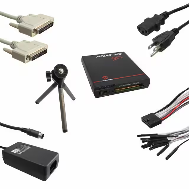
Microchip Technology ICE2000
- Part No.:
- ICE2000
- Manufacturer:
- Microchip Technology
- Category:
- Programmers, Emulators, and Debuggers
- Package:
- Datasheet:
-
 ICE2000.pdf
- Description:
- EMULATOR MPLAB-ICE 2000 POD
- Quantity:
- Payment:

- Shipping:

Inventory:1,177
Please send an inquiry. Send us your inquiry, and we will respond immediately.
Product details
Overview
ICE2000 from Microchip Technology Inc. is an in-circuit emulator system for PICmicro® microcontrollers, comprising an emulator pod, processor modules, device adapters, and transition sockets. It supports emulation of DIP, SDIP, PLCC, SOIC, SSOP, PQFP, and TQFP-packaged PIC MCUs across voltage ranges (2.0V–5.5V), frequencies (32 kHz to max device-rated speed), and oscillator modes (HS/XT/LP/RC/EC), with field-replaceable flex circuit cable and software-configurable power/clock sourcing.
For engineers reviewing the ICE2000 datasheet, ICE2000 pinout, ICE2000 application, or ICE2000 equivalent, this page delivers verified technical context on modular emulation architecture, target interface compatibility, low-voltage operation constraints, freeze-mode peripheral control, and adapter-level oscillator routing - all critical for embedded firmware debug, production validation, and legacy PIC MCU development workflows.
Technical Context
The ICE2000 system implements a modular architecture where interchangeable processor modules (e.g., PCM16XA0, PCM17XA0) contain bond-out PICmicro silicon and low-voltage emulation logic, while device adapters provide physical interface, target power routing, and dedicated oscillator circuitry (including secondary 32–40 kHz TIMER1 oscillators on select adapters). Emulation clocking is configurable between internal programmable source (in pod) and external target board source.
Processor module power is software-selectable: supplied by emulator pod (+5 V only) or target system (2.0–5.5 V), with automatic low-voltage mode activation below 4.55 V ±120 mV that limits maximum operating frequency per device data sheet ratings. Adapter-level mechanical switches (e.g., S1–S4) and jumpers (e.g., J1, T1OSC) enable precise signal routing for MCLR, OSC1/OSC2, T0CKI, CCP1, and T1OSI/T1OSO pins per target device requirements.
Key Specifications
| Parameter | Value and Actual Design Meaning |
|---|---|
| Emulation Target | PICmicro® MCUs in DIP, SDIP, PLCC, SOIC, SSOP, PQFP, TQFP packages via modular processor modules and adapters. |
| Operating Voltage Range | 2.0 V to 5.5 V; automatically enables Low Voltage Mode below 4.55 V ±120 mV, limiting max frequency per device datasheet. |
| Frequency Support | 32 kHz minimum; up to max rated frequency of emulated PIC device, reduced at voltages <4.5 V. |
| Clock Source Options | Internal (pod-based programmable clock) or external (target board oscillator); external clock requires external power mode. |
| Oscillator Mode Coverage | HS, XT, LP, LF, RC, and EC modes supported; OSC1/OSC2 load = 5–10 pF; RC network frequency may vary vs. actual device. |
| Freeze Mode Support | Available on all processor modules except PCM16XA0; halts peripheral timers during breakpoint/suspend without disabling interrupts. |
| Flex Circuit Cable | Field-replaceable custom cable; parasitic capacitance ≤120 pF affects analog function accuracy per device datasheet specs. |
Availability
ICE2000 is available at Aetrix Electronics and suitable for PIC MCU firmware development, production validation, legacy embedded system maintenance, and educational microcontroller labs requiring stable component supply and long-term toolchain continuity.
Supply support for ICE2000 includes scheduled delivery planning, volume procurement assistance, BOM continuity management, traceable sourcing, and lifecycle availability coordination for OEM customers, industrial embedded developers, connected-device designers, and electronics production programs.
Manufacturer
Microchip Technology Inc. is a U.S.-based semiconductor company specializing in microcontrollers, analog devices, and development tools for embedded control applications.
The ICE2000 product line was designed as a cost-effective, modular in-circuit emulator platform for rapid debugging and verification of PICmicro® MCU-based designs across multiple package types and voltage/frequency configurations.
FAQ
What is the ICE2000 and how does it differ from modern debuggers like REAL ICE?
The ICE2000 is Microchip's legacy in-circuit emulator system introduced in the early 2000s, using bond-out processor modules and physical device adapters to emulate PICmicro® MCUs. Unlike REAL ICE - which uses on-chip debug hardware (ICD) and USB connectivity - the ICE2000 relies on parallel-port host connection, separate emulator pod, and hardware-level signal injection. The ICE2000 supports older PIC families (e.g., PIC12C, PIC16C) not compatible with newer debug architectures, making it essential for maintaining legacy designs where source code or hardware revisions are unavailable.
Can the ICE2000 emulate PIC microcontrollers operating below 2.0 V?
No. The ICE2000 processor modules require a minimum operating voltage of 2.0 V for target-powered operation, as specified in Section 4.1.4 of the DS51140M documentation. Operation below 2.0 V is not supported, and attempting to do so may result in unstable emulation, failure to initialize, or incorrect peripheral timing behavior. For sub-2.0 V applications, hardware-level voltage translation or alternative debug solutions would be required - neither of which is natively supported by the ICE2000 system.
How does the ICE2000 handle oscillator configuration for devices using RC networks or EC mode?
The ICE2000 supports RC and EC oscillator modes via its device adapter's dedicated oscillator circuitry and configurable mechanical switches. However, RC network frequency may deviate from the actual device due to emulator circuitry parasitics; users must empirically adjust RC values or switch to internal clock sourcing (Section 4.3.1) for precise frequency control. For EC mode, DVA17XXXX0 adapters omit OSC/4 support, while DVA17XXXX1 adapters explicitly enable it - confirming mode compatibility is adapter-specific and must be verified against the target PIC device's datasheet and the adapter's part number.
Is the ICE2000 compatible with Windows 10 or later operating systems?
The ICE2000 was originally designed for Windows 98/2000/XP and relies on legacy parallel-port (LPT) communication and 16-bit driver architecture. While basic functionality may be achieved on Windows 10 via compatibility mode or virtual machine hosting Windows XP, official Microchip support ended with MPLAB IDE v8.x. No native 64-bit drivers exist, and USB-to-parallel adapters are not guaranteed to work due to strict timing requirements. Users should verify host OS compatibility through Microchip's archived MPLAB ICE 2000 User's Guide (DS51488) and test with original hardware before deployment.
What safety precautions apply when connecting the ICE2000 to a live target board?
When connecting the ICE2000 to a powered target board, ensure the emulator pod is powered first and the processor module is fully seated before applying target power. Avoid I/O contention by using ~100 Ω current-limiting resistors on bidirectional pins during development (Section 4.4). Never pull on the flex circuit cable to remove the processor module - use the end-cap fins instead. Also, disconnect the device adapter from the flex cable when emulator power is active but no target is attached to prevent loading effects on target I/O pins.
ICE2000 Specifications
- Product attributes
- Attribute value
- Manufacturer:
- Microchip Technology
- Series:
- MPLAB® ICE2000
- Packaging:
- Bulk
- Product Status:
- Obsolete
- Type:
- Programmer
- For Use With/Related Products:
- PIC Micro® MCU
- Contents:
- Board(s)
ICE2000 FAQ
1.How can I place an order for ICE2000 through Aetrix?
Please submit a Request for Quotation (RFQ) for ICE2000 on Aetrix. Our sales agent will provide a competitive quotation and guide you through the order confirmation once you accept the terms.
2.Are the price and stock information for ICE2000 reliable?
The price and inventory of ICE2000 are updated periodically and may fluctuate due to market conditions. Stock and pricing data are typically refreshed every 24 hours. Quotation validity for ICE2000 is usually 5 days.
3.What payment methods are accepted for ICE2000?
We accept Wire Transfer, PayPal, Credit Card, Western Union, MoneyGram, and Escrow for ICE2000 transactions.
Note: Certain payment methods may incur a processing fee.
4.How is shipping managed for ICE2000?
ICE2000 orders can be shipped via leading logistics carriers, including DHL, UPS, FedEx, TNT, or Registered Mail.
Once your ICE2000 order is processed, you will receive an email with the shipment details and tracking number.
Note: Tracking information may take up to 24 hours to appear. Express delivery typically takes 3–5 business days.
5.How can I obtain technical support or documentation for ICE2000?
For technical support, including ICE2000 datasheets, pinout diagrams, or application guidance, please contact our engineering support team. They can provide detailed documentation and assistance for your ICE2000 requirements.
6.How does Aetrix verify that ICE2000 is sourced from the original manufacturer or authorized distributors?
All ICE2000 products on Aetrix are procured from qualified distributors and authorized channels. Our dedicated quality assurance team conducts strict verification, including traceability checks and, if necessary, third-party testing. This ensures that ICE2000 meets industry standards.
7.What is the process for return or replacement of ICE2000?
All ICE2000 units undergo pre-shipment inspection (PSI). If there is an issue with ICE2000, returns or replacements are accepted under the following conditions:
1.Quantity discrepancies, incorrect items, or visible external defects (such as breakage or corrosion), acknowledged by Aetrix.
2.The issue is reported within 90 days of delivery.
3.The ICE2000 part is unused and in its original packaging.
Return procedure for ICE2000:
1.Submit a request within 90 days.
2.Obtain a Return Material Authorization (RMA) from Aetrix.
ICE2000 Tags
-
STLINK-V3MODS
STMicroelectronics
-
STLINK-V3MINIE
STMicroelectronics
-
ESP-PROG
Espressif Systems

-
SC0889
Raspberry Pi
-
2548
Adafruit Industries LLC
-
PG164100
Microchip Technology
-
ST-LINK/V2
STMicroelectronics
-
STLINK-V3SET
STMicroelectronics
-
NU-LINK-PRO
Nuvoton Technology Corporation
-
ARM-USB-TINY-H
Olimex LTD
-
MCU-LINK-PRO
NXP Semiconductors
-
410-308-B
Digilent, Inc.
Tech Hub

TTL and CMOS logic families differ in thresholds, loading, output drive, power and timing. This engineering guide compares 74HC and 74HCT, calculates noise margins and checks 3.3 V/5 V compatibility.

A practical engineering guide to 3.3V and 5V logic compatibility, input thresholds, resistor dividers, translator ICs, MOSFET level shifting, I2C pull-ups, timing limits and power-sequencing risks.

The 74HC595 uses push-pull logic outputs, while the TPIC6B595 uses 50 V open-drain DMOS sinks for higher-power loads. This guide compares timing, current limits, 3.3 V interfacing, load wiring, thermal…

The 74HC595 converts serial data into eight stable parallel outputs. This guide covers pin functions, shift and storage timing, OE and MR behavior, drive-current limits, cascading, voltage compatibilit…

A technical comparison of level-sensitive latches and edge-triggered flip-flops, covering timing windows, setup and hold limits, master–slave operation, time borrowing, race-through, HDL inference and…

A D latch stores one bit while Enable controls when data can pass. This reference covers gate-level operation, truth tables, transparency, setup and hold timing, LE versus OE, common ICs and practical …

An SR latch stores one bit through cross-coupled feedback. This engineering reference covers NOR and NAND implementations, truth tables, forbidden-state recovery, gated operation, switch debouncing, fa…

Latch circuits retain one bit through feedback. This technical reference covers SR and D latches, truth tables, transparency, timing limits, latch-versus-flip-flop behavior, applications and common log…

An engineering guide to LED driver operation, constant-current and constant-voltage outputs, linear and switching topologies, dimming, IC selection, calculations, replacement compatibility, and fault c…

Operational amplifier guide covering op amp basics, feedback, ideal vs real op amps, common configurations, buffer circuits, offset, bias current, gain-bandwidth, slew rate, rail-to-rail limits and sel…


