
 My Inquiry
 My Account


Renesas ICM7218AIJI
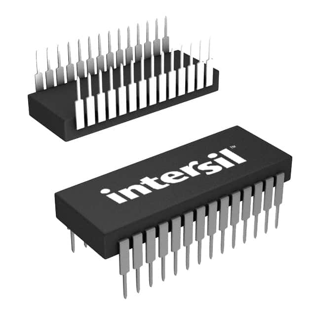
- Part No.:
- ICM7218AIJI
- Manufacturer:
- Renesas
- Category:
- Display Drivers
- Package:
- 28-CDIP (0.600", 15.24mm)
- Datasheet:
-
 ICM7218AIJI.pdf
- Description:
- IC DRVR 7 SEG 8 DIGIT 28CERDIP
- Quantity:
- Payment:

- Shipping:

Inventory:4,268
Please send an inquiry. Send us your inquiry, and we will respond immediately.
Product details
Overview
ICM7218AIJI from Intersil is a microprocessor-compatible 8-digit LED display decoder/driver IC with common anode output configuration, integrated 8-byte static RAM, hexadecimal/Code B decoding, and shutdown mode. It operates from a single 5V supply, supports inter-digit blanking, delivers up to 200mA digit drive current, and functions across –40°C to +85°C for industrial panel meters and instrumentation displays.
For engineers reviewing the ICM7218AIJI datasheet, ICM7218AIJI pinout, ICM7218AIJI application, or ICM7218AIJI equivalent, this device serves as a self-contained multiplexed LED interface requiring no external segment drivers, clock generation, or memory - ideal for space-constrained microcontroller-based display systems where deterministic timing, low-power shutdown, and direct segment/digit control are critical.
Technical Context
The ICM7218AIJI implements sequential addressing via two control lines (WRITE and MODE): MODE high loads 4-bit control words (DECODE, HEXA/CODE B, SHUTDOWN, DATA COMING), while MODE low enables 8-bit data writes to internal RAM on each WRITE pulse. Its on-chip multiplex oscillator runs at ~250Hz per digit, with 10µs inter-digit blanking to prevent ghosting.
It integrates dual 7-segment decoders (Hexadecimal and Code B), digit/segment drivers with 20kΩ pull-up resistors for common anode operation, and retains display data down to 2V supply during shutdown - all in a single 28-lead CERDIP package without external components for basic operation.
Key Specifications
| Parameter | Value and Actual Design Meaning |
|---|---|
| Display Digits | 8-digit multiplexed LED interface with dedicated digit and segment drivers |
| Supply Voltage | 4V to 6V operating range; retains memory down to 2V in shutdown mode |
| Digit Drive Current | 200mA typical per digit at 12% duty cycle (common anode) |
| Segment Drive Current | 40mA peak segment current supports standard LED brightness |
| Scan Rate | 250Hz per digit ensures flicker-free visible display |
| Memory | 8-byte static RAM stores full 8-digit display state without host refresh |
| Decoding Modes | Hexadecimal (0–9, A–F) and Code B (–, blank, H, L, P) selectable via pin |
| Shutdown Current | 10µA typical quiescent current disables oscillator, drivers, and display |
Pinout & Package
ICM7218AIJI is housed in a 28-lead Ceramic Dual-In-Line Package (CERDIP) with frit seal, RoHS-compliant matte tin termination (e3), and thermal resistance θJA = 55°C/W. Pin 1 is identified by a notch; package conforms to MIL-STD-1835 GDIP1-T28 (F28.6).
| Pin/Terminal | Circuit Role | Design Meaning |
|---|---|---|
| WRITE (Pin 8) | Control strobe input | Low-to-high transition loads control word or display data based on MODE state |
| MODE (Pin 9) | Address mode selector | High enables control-word loading; low enables sequential 8-bit data write |
| ID4 (SHUTDOWN) (Pin 10) | Power control input | Low disables oscillator, digit/segment drivers, and display; memory retained |
| ID5 (DECODE) (Pin 6) | Decoder enable | Low enables Hexadecimal/Code B decoding; high bypasses decoder (direct segment control) |
| ID6 (HEXA/CODE B) (Pin 5) | Decode format select | High selects Hexadecimal; low selects Code B character set |
| ID7 (DATA COMING) (Pin 7) | Data readiness flag | High signals valid data present on ID0–ID3 for next WRITE pulse |
| ID0–ID3 (Pins 12,11,13,14) | Data/control inputs | Carry 4-bit control or lower nibble of 8-bit display data; ID7 carries decimal point |
| DIGIT1–DIGIT8 (Pins 15,16,23,20,17,22,21,18) | Common-anode digit drivers | Active-low outputs sink current to LED common cathodes in multiplexed scan |
| SEG a–g, D.P. (Pins 27,3,1,25,2,24,26,4) | Segment drivers | Source current to LED anodes; D.P. active-low for decimal point control |
| VDD (Pin 19) | Power supply | +5V nominal supply; supports operation down to 4V for data writes |
| VSS (Pin 28) | Ground reference | Return path for all internal logic and driver circuits |
Key Features
| Feature | Design Value |
|---|---|
| Integrated 8-byte static RAM | Eliminates need for external memory; retains full 8-digit display state autonomously |
| Two decoding formats | Hexadecimal (alphanumeric) and Code B (with minus, blank, H/L/P) support diverse UI requirements |
| Inter-digit blanking | 10µs blanking interval prevents cross-digit ghosting in multiplexed operation |
| Single-supply operation | 5V-only interface simplifies power design; no level shifters or auxiliary supplies needed |
| Shutdown mode | Reduces supply current to 10µA while preserving display memory for instant resume |
| Direct segment control | No-decode mode allows microcontroller to drive individual segments for custom symbols or status indicators |
Applications
| Industrial Panel Meter | Test Equipment Display |
|---|---|
Use Scenario: 8-digit numeric readout in benchtop multimeters or power analyzers with microcontroller host. IC Role / Device Role / Timing Role: Primary display controller handling multiplex timing, segment decoding, and digit sequencing independently. Use Value: Reduces MCU firmware overhead by offloading display memory management and scan timing; supports leading-zero blanking via Code B. | Use Scenario: Front-panel LED display in programmable logic analyzers or signal generators requiring alphanumeric status. IC Role / Device Role / Timing Role: Interface between 8048-family or similar microcontrollers and common-anode 7-segment modules. Use Value: Enables Hexadecimal mode for hex register values and Code B for error codes (e.g., "E", "H", "P") without external logic. |
| Embedded Instrumentation | Legacy Control System Upgrade |
Use Scenario: Retrofit display module in HVAC controllers or PLC I/O panels using aging 8-bit MCUs. IC Role / Device Role / Timing Role: Standalone display driver replacing discrete transistor arrays and shift registers. Use Value: Simplifies PCB layout with integrated drivers and memory; supports –40°C to +85°C operation for harsh environments. | Use Scenario: Replacing obsolete discrete LED driver solutions in legacy medical or telecom equipment. IC Role / Device Role / Timing Role: Drop-in functional replacement for multi-chip display interfaces with identical CERDIP footprint. Use Value: Maintains existing board layout while adding shutdown mode and improved decode flexibility over prior designs. |
Equivalent & Alternatives
The following parts are listed as comparable options for similar LED display driver applications.
| Alternative Part | Technical Difference | Application Difference | Selection Advice |
|---|---|---|---|
| ICM7218BIJI | Common cathode output configuration; identical pinout and control logic but inverted driver polarity | Requires common-cathode LED displays; not interchangeable without display redesign | Select ICM7218BIJI only when driving common-cathode displays; same timing and memory behavior |
| MAX7219CNG | Serial SPI interface (vs parallel bus); includes intensity control, scan limit, and hardware test modes | Supports daisy-chaining and dynamic brightness adjustment; lacks direct No-Decode segment control | Choose MAX7219CNG for SPI-based systems needing cascading or programmable brightness; not pin-compatible |
Compared with ICM7218BIJI, the ICM7218AIJI enables direct use with common-anode displays without level-shifting circuitry; versus MAX7219CNG, it offers simpler parallel interfacing and deterministic write timing but lacks serial configurability and intensity scaling.
Availability
ICM7218AIJI is available at Aetrix Electronics and suitable for industrial panel meters, test equipment displays, embedded instrumentation, and legacy control system upgrades requiring stable component supply, long-lifecycle support, and hermetic packaging for reliability-critical applications.
Supply support for ICM7218AIJI includes scheduled delivery planning, volume procurement assistance, BOM continuity management, traceable sourcing, and lifecycle availability coordination for OEM customers, industrial embedded developers, connected-device designers, and electronics production programs.
Manufacturer
Intersil Corporation is a provider of precision analog and power management ICs, now part of Renesas Electronics, with expertise in high-reliability industrial and infrastructure solutions.
The ICM7218 product line was designed for microprocessor-based LED display interfacing in industrial instrumentation, offering integrated memory, decoding, and driver capability in a single hermetic package.
FAQ
What display configurations does the ICM7218AIJI support?
The ICM7218AIJI supports common anode 7-segment LED displays with decimal point. It drives eight digits using multiplexed scanning at ~250Hz per digit and provides both Hexadecimal (0–9, A–F) and Code B (–, blank, H, L, P) decoding. The ICM7218AIJI does not support common cathode displays - that function is implemented in the ICM7218BIJI variant.
How does the ICM7218AIJI handle display memory and data loading?
The ICM7218AIJI contains 8 bytes of static RAM to store digit data. Data is loaded sequentially: first a control word (via MODE=high and WRITE pulse) configures decode/shutdown mode, then eight successive WRITE pulses (with MODE=low) fill all 8 memory locations. Once full, further WRITE pulses are ignored until a new control word is issued - ensuring deterministic, non-overrun memory updates.
Can the ICM7218AIJI operate below 5V, and what happens in shutdown mode?
Yes - the ICM7218AIJI operates from 4V to 6V normally, and retains display memory down to 2V in shutdown mode. In shutdown (ID4=low), the multiplex oscillator stops, digit/segment drivers disable, and supply current drops to ~10µA. Data remains intact, and the device resumes display immediately upon exit from shutdown, making it suitable for battery-backed or low-power standby applications.
What is the purpose of the DATA COMING (ID7) signal on the ICM7218AIJI?
ID7 (DATA COMING) signals whether valid display data is present on ID0–ID3 before a WRITE pulse. When ID7=high, the next WRITE pulse (with MODE=low) loads the 4-bit nibble into the current memory location. This handshake prevents spurious writes and enables synchronized data transfer from microcontrollers with variable bus timing - a key reliability feature in noise-prone industrial environments.
Does the ICM7218AIJI require external passive components for basic operation?
Yes - a 0.1µF ceramic capacitor plus a 47µF electrolytic capacitor between VDD and VSS is recommended to suppress multiplex-induced supply noise. No external clock, resistors, or transistors are required for core functionality, as the ICM7218AIJI integrates the oscillator, memory, decoders, and drivers. Pull-up/down resistors are unnecessary due to built-in three-level input biasing on relevant control pins.
ICM7218AIJI Specifications
- Product attributes
- Attribute value
- Manufacturer:
- Renesas
- Series:
- -
- Package/Case:
- 28-CDIP (0.600", 15.24mm)
- Packaging:
- Tube
- Product Status:
- Obsolete
- Display Type:
- LED
- Configuration:
- 7 Segment
- Interface:
- Serial
- Digits or Characters:
- 8 Digits
- Current - Supply:
- 2.5 mA
- Voltage - Supply:
- 4V ~ 6V
- Operating Temperature:
- -40°C ~ 85°C
- Grade:
- -
- Qualification:
- -
- Mounting Type:
- Through Hole
- Supplier Device Package:
- 28-CerDip
ICM7218AIJI FAQ
1.How can I place an order for ICM7218AIJI through Aetrix?
Please submit a Request for Quotation (RFQ) for ICM7218AIJI on Aetrix. Our sales agent will provide a competitive quotation and guide you through the order confirmation once you accept the terms.
2.Are the price and stock information for ICM7218AIJI reliable?
The price and inventory of ICM7218AIJI are updated periodically and may fluctuate due to market conditions. Stock and pricing data are typically refreshed every 24 hours. Quotation validity for ICM7218AIJI is usually 5 days.
3.What payment methods are accepted for ICM7218AIJI?
We accept Wire Transfer, PayPal, Credit Card, Western Union, MoneyGram, and Escrow for ICM7218AIJI transactions.
Note: Certain payment methods may incur a processing fee.
4.How is shipping managed for ICM7218AIJI?
ICM7218AIJI orders can be shipped via leading logistics carriers, including DHL, UPS, FedEx, TNT, or Registered Mail.
Once your ICM7218AIJI order is processed, you will receive an email with the shipment details and tracking number.
Note: Tracking information may take up to 24 hours to appear. Express delivery typically takes 3–5 business days.
5.How can I obtain technical support or documentation for ICM7218AIJI?
For technical support, including ICM7218AIJI datasheets, pinout diagrams, or application guidance, please contact our engineering support team. They can provide detailed documentation and assistance for your ICM7218AIJI requirements.
6.How does Aetrix verify that ICM7218AIJI is sourced from the original manufacturer or authorized distributors?
All ICM7218AIJI products on Aetrix are procured from qualified distributors and authorized channels. Our dedicated quality assurance team conducts strict verification, including traceability checks and, if necessary, third-party testing. This ensures that ICM7218AIJI meets industry standards.
7.What is the process for return or replacement of ICM7218AIJI?
All ICM7218AIJI units undergo pre-shipment inspection (PSI). If there is an issue with ICM7218AIJI, returns or replacements are accepted under the following conditions:
1.Quantity discrepancies, incorrect items, or visible external defects (such as breakage or corrosion), acknowledged by Aetrix.
2.The issue is reported within 90 days of delivery.
3.The ICM7218AIJI part is unused and in its original packaging.
Return procedure for ICM7218AIJI:
1.Submit a request within 90 days.
2.Obtain a Return Material Authorization (RMA) from Aetrix.
ICM7218AIJI Tags

-
PCA8561AHN/AY
NXP Semiconductors

-
SN74LS47N
Texas Instruments

-
PCF85176T/1Y
NXP Semiconductors
-
PCF85176H/1,518
NXP Semiconductors

-
BU9796AMUV-E2
Rohm Semiconductor
-
PCA85176H/Q900/1,5
NXP Semiconductors
-
PCF8537AH/1,518
NXP Semiconductors

-
LM3914VX/NOPB
Texas Instruments

-
PCF85134HL/1,118
NXP Semiconductors

-
AS1115-BSST
ams-OSRAM USA INC.
-
PCA8534AH/Q900/1,5
NXP Semiconductors
-
LM3914V/NOPB
Texas Instruments
Tech Hub

TTL and CMOS logic families differ in thresholds, loading, output drive, power and timing. This engineering guide compares 74HC and 74HCT, calculates noise margins and checks 3.3 V/5 V compatibility.

A practical engineering guide to 3.3V and 5V logic compatibility, input thresholds, resistor dividers, translator ICs, MOSFET level shifting, I2C pull-ups, timing limits and power-sequencing risks.

The 74HC595 uses push-pull logic outputs, while the TPIC6B595 uses 50 V open-drain DMOS sinks for higher-power loads. This guide compares timing, current limits, 3.3 V interfacing, load wiring, thermal…

The 74HC595 converts serial data into eight stable parallel outputs. This guide covers pin functions, shift and storage timing, OE and MR behavior, drive-current limits, cascading, voltage compatibilit…

A technical comparison of level-sensitive latches and edge-triggered flip-flops, covering timing windows, setup and hold limits, master–slave operation, time borrowing, race-through, HDL inference and…

A D latch stores one bit while Enable controls when data can pass. This reference covers gate-level operation, truth tables, transparency, setup and hold timing, LE versus OE, common ICs and practical …

An SR latch stores one bit through cross-coupled feedback. This engineering reference covers NOR and NAND implementations, truth tables, forbidden-state recovery, gated operation, switch debouncing, fa…

Latch circuits retain one bit through feedback. This technical reference covers SR and D latches, truth tables, transparency, timing limits, latch-versus-flip-flop behavior, applications and common log…

An engineering guide to LED driver operation, constant-current and constant-voltage outputs, linear and switching topologies, dimming, IC selection, calculations, replacement compatibility, and fault c…

Operational amplifier guide covering op amp basics, feedback, ideal vs real op amps, common configurations, buffer circuits, offset, bias current, gain-bandwidth, slew rate, rail-to-rail limits and sel…


