
 My Inquiry
 My Account


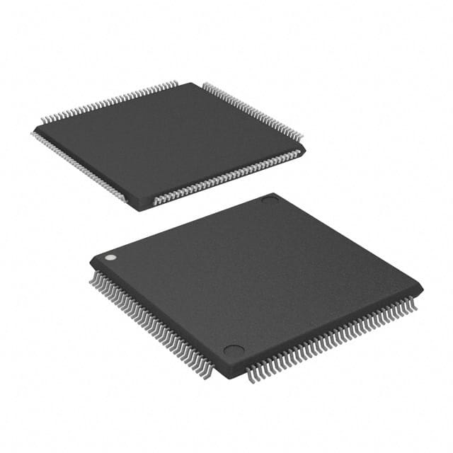
Renesas IDT79RC32V364-133DAG
- Part No.:
- IDT79RC32V364-133DAG
- Manufacturer:
- Renesas
- Category:
- Microprocessors
- Package:
- 144-LQFP
- Datasheet:
-
 IDT79RC32V364-133DAG.pdf
- Description:
- IC MPU 133MHZ 144TQFP
- Quantity:
- Payment:

- Shipping:

Inventory:3,539
Please send an inquiry. Send us your inquiry, and we will respond immediately.
Product details
Overview
IDT79RC32V364-133DAG from Integrated Device Technology, Inc. is a 32-bit embedded microprocessor based on the RISCore32300 CPU core, implementing the MIPS 32 ISA with DSP extensions. It operates at 133 MHz, delivers 175 Dhrystone MIPS, integrates 8 kB instruction and 2 kB data caches (2-way set associative), supports RC5000-compatible MMU with 32-page TLB, and targets cost-sensitive communications and xDSL equipment.
For engineers reviewing the IDT79RC32V364-133DAG datasheet, IDT79RC32V364-133DAG pinout, IDT79RC32V364-133DAG application, or IDT79RC32V364-133DAG equivalent, key selection considerations include its 133 MHz clock speed, 3.3 V core/I/O operation, industrial temperature range (–40°C to +85°C), 66 million MAC/sec DSP capability, and enhanced JTAG debug interface for in-circuit emulation.
Technical Context
The IDT79RC32V364-133DAG implements a scalar 5-stage pipeline optimized for low branch/load latency and high-frequency operation. Its RISCore32300 core executes MIPS 32 instructions with architectural enhancements including conditional move, prefetch (PREF), MAD/MSUB, and CLZ/CLO instructions - all directly supporting integer DSP workloads.
It features a fully associative 16-entry TLB mapping up to 512 MB of memory with programmable page sizes (4 kB–16 MB), per-page cache coherency attributes (uncached/write-through/write-back), and deterministic real-time access via TLB locking. The system interface provides a 32-bit multiplexed A/D bus with programmable port width (8/16/32-bit), burst support, and integrated DMA arbiter.
Key Specifications
| Parameter | Value and Actual Design Meaning |
|---|---|
| Clock Frequency | 133 MHz - defines maximum sustained instruction throughput and timing budget for external bus cycles. |
| Performance | 175 Dhrystone MIPS - benchmarked integer performance metric indicating execution efficiency in control-oriented embedded code. |
| Instruction Cache | 8 kB, 2-way set associative, virtually indexed/physically tagged - enables single-cycle instruction fetch with parallel address translation. |
| Data Cache | 2 kB, 2-way set associative, write-back/write-through configurable per page - reduces memory latency for data-intensive operations while supporting deterministic real-time behavior. |
| MMU / TLB | 32-page virtual-to-physical mapping via 16-entry TLB with variable page size (4 kB–16 MB) and lockable entries - enables flexible memory management for OS-based systems without performance penalty. |
| DSP Capability | 66 million multiply-accumulate (MAC) operations/sec - hardware-accelerated integer arithmetic for telecom and signal processing algorithms. |
| Power Consumption | Typical 700 mW @ 133 MHz; standby <300 mW - enables thermal-noise-free operation in fanless industrial enclosures. |
| Operating Temperature | –40°C to +85°C - qualified for industrial-grade deployment in xDSL modems, network edge devices, and consumer gateways. |
Pinout & Package
Package: 144-pin TQFP (Thin Quad Flat Package), 20 mm × 20 mm, 0.5 mm pitch, lead-free compliant.
| Pin/Terminal | Circuit Role | Design Meaning |
|---|---|---|
| AD(31:4) | Multiplexed Address/Data Bus | High-order 28 bits shared between address and data phases; supports 32-bit transfers with ALE synchronization. |
| AD(3:0) | Size/Data Bus | Encodes transfer width (1–16 bytes); carries low-order data during data phase. |
| ALE | Address Latch Enable | Controls external latch sampling of AD bus during address phase; defines setup/hold timing window. |
| ADS* | Address Strobe | Active-low start-of-transaction signal; inverse of ALE, used for bus arbitration and cycle detection. |
| BE*(3:0) | Byte Enables | Selects active byte lanes (0–3) per transfer; determines which of four 8-bit lanes participate in 8/16/32-bit accesses. |
| CIP* | Cycle-in-Progress | Asserted throughout bus transaction (address + all data phases); signals ongoing activity to peripherals and DMA controllers. |
| I/D* | Instruction/Data Indicator | High = instruction fetch; low = data access - enables separate caching policies and memory subsystem optimization. |
| Rd*/Wr* | Read/Write Control | Active-low signals defining direction and type of memory or I/O transfer; drive external memory controller state machines. |
| BusReq*/BusGnt* | DMA Arbitration Interface | Enables external masters (e.g., Ethernet MAC, SDRAM controller) to seize bus control without CPU intervention. |
| TCK/TDI/TDO | JTAG Boundary Scan | Supports IEEE 1149.1 compliance, in-circuit debugging, and real-time trace via PCST[2:0] in enhanced mode. |
Key Features
| Feature | Design Value |
|---|---|
| MIPS 32 ISA with DSP Extensions | Native support for MAD, MSUB, PREF, and CLZ/CLO instructions accelerates telecom and audio codec execution without coprocessor overhead. |
| Per-Page Cache Coherency Control | TLB entry attributes allow independent write-back/write-through/uncached policy per virtual page - optimizes bus bandwidth for mixed workloads (e.g., stack vs. packet buffers). |
| Cache Locking at Line Level | Enables deterministic real-time response by locking critical code/data into I-cache or D-cache - eliminates worst-case cache miss penalties. |
| Enhanced JTAG Debug Interface | Provides both Run-Time Mode (standard ICE) and Real-Time Mode (PCST[2:0] trace pins) - reduces debug hardware cost while enabling cycle-accurate program flow analysis. |
| Programmable Bus Turnaround & Width | Width[1:0] and Port Width Control Register allow seamless interfacing to 8/16/32-bit memories and peripherals - simplifies board design and lowers BOM cost. |
| Low-Power WAIT Instruction | Halts CPU pipeline and clocks while preserving register/state - reduces average power in idle periods without requiring external power sequencing logic. |
Applications
| DSL Modem Baseband Processing | xDSL Line Card Control |
|---|---|
Use Scenario: Real-time ADSL/SHDSL line initialization, echo cancellation, and framing in residential gateway hardware. IC Role / Device Role / Timing Role: Primary integer DSP and control processor executing firmware with tight interrupt latency requirements. Use Value: 66 million MAC/sec and early-restart cache miss handling enable sub-100 µs response to line events without external DSP offload. | Use Scenario: Managing multiple DSL PHYs, ATM/PTM segmentation, QoS scheduling, and SNMP agent in carrier-class line cards. IC Role / Device Role / Timing Role: System-level controller coordinating DMA, memory-mapped PHY registers, and interrupt-driven protocol stacks. Use Value: RC5000-compatible MMU with 32-page TLB and per-page cache attributes allows safe, high-bandwidth access to multiple PHY register spaces and packet buffers. |
| Consumer VoIP Gateway | Industrial Protocol Converter |
Use Scenario: SIP signaling stack, G.711/G.729 codec execution, and Ethernet/Wi-Fi bridging in home VoIP adapters. IC Role / Device Role / Timing Role: Unified application processor running Linux RTOS with deterministic interrupt handling for voice jitter control. Use Value: 175 Dhrystone MIPS and 8 kB I-cache ensure soft real-time SIP call setup and concurrent codec decode within 10 ms deadlines. | Use Scenario: Translating Modbus TCP to CANopen or Profibus DP in factory automation gateways operating in harsh environments. IC Role / Device Role / Timing Role: Deterministic protocol engine managing dual-network interfaces with guaranteed response to fieldbus interrupts. Use Value: Industrial temperature rating (–40°C to +85°C), WAIT instruction power management, and TLB locking ensure reliable operation under thermal stress and voltage fluctuation. |
Equivalent & Alternatives
The following parts are listed as comparable options for similar embedded microprocessor applications.
| Alternative Part | Technical Difference | Application Difference | Selection Advice |
|---|---|---|---|
| IDT79RC32V364-100DAG | 100 MHz clock, lower power (550 mW typical), reduced MAC throughput (50 M MAC/sec) | Suitable for cost-optimized DSL CPE where full 133 MHz headroom is unnecessary | Select when thermal envelope or BOM cost constraints outweigh peak performance needs |
| IDT79RC32V364-133DBG | Same electrical specs but 256-pin PBGA package (17 mm × 17 mm) instead of 144-pin TQFP | Required for designs needing higher I/O count or improved thermal dissipation in compact layouts | Choose for space-constrained industrial boards requiring better heat spreading or additional signal routing layers |
Compared with IDT79RC32V364-100DAG, the IDT79RC32V364-133DAG delivers 33% higher clock rate and 32% more MAC throughput - critical for multi-channel VoIP or vectoring-capable DSL. Compared with IDT79RC32V364-133DBG, the DAG variant offers identical functionality in a smaller footprint and lower assembly cost, though with reduced thermal margin and fewer I/Os.
Availability
IDT79RC32V364-133DAG is available at Aetrix Electronics and suitable for DSL modem baseband processing, xDSL line card control, consumer VoIP gateway development, and industrial protocol converter designs requiring stable component supply across extended product lifecycles.
Supply support for IDT79RC32V364-133DAG includes scheduled delivery planning, volume procurement assistance, BOM continuity management, traceable sourcing, and lifecycle availability coordination for OEM customers, industrial embedded developers, connected-device designers, and electronics production programs.
Manufacturer
Integrated Device Technology, Inc. (IDT) was a fabless semiconductor company specializing in high-performance timing, memory interface, RF, and embedded processor solutions before its acquisition by Renesas Electronics in 2019.
The IDT79RC32V364-133DAG belongs to the RISController™ family - designed specifically for cost-sensitive, real-time embedded systems requiring MIPS software compatibility, integrated DSP acceleration, and industrial-grade reliability in communications infrastructure.
FAQ
What is the maximum operating frequency of the IDT79RC32V364-133DAG?
The IDT79RC32V364-133DAG is rated for operation at 133 MHz - this is its guaranteed maximum clock frequency under industrial temperature conditions (–40°C to +85°C) and 3.3 V ±5% supply. It achieves 175 Dhrystone MIPS at this speed, with pipeline timing validated across process corners and voltage extremes per the original IDT datasheet DSC 4510.
Does the IDT79RC32V364-133DAG support cache locking, and how is it implemented?
Yes, the IDT79RC32V364-133DAG supports cache locking at the individual cache line level for both instruction and data caches. Locking is controlled via CP0 registers and allows critical code or data blocks to remain resident in cache, eliminating worst-case miss penalties. This feature is essential for hard real-time applications such as DSL line initialization where deterministic interrupt latency is required - and is explicitly documented in the "Cache Memory" section of the IDT79RC32V364-133DAG datasheet.
What debug capabilities does the IDT79RC32V364-133DAG provide beyond standard JTAG?
The IDT79RC32V364-133DAG implements an Enhanced JTAG interface with two operational modes: Run-Time Mode (standard IEEE 1149.1 debugging) and Real-Time Mode, which outputs non-sequential program counter values on dedicated PCST[2:0] pins synchronized to the internal clock. This enables cycle-accurate instruction trace without requiring expensive external logic analyzers - a capability confirmed in the "Debug Support" section of the official IDT documentation for the IDT79RC32V364-133DAG.
Is the IDT79RC32V364-133DAG pin-compatible with other members of the RC32364 family?
Yes, the IDT79RC32V364-133DAG shares identical pinout and electrical characteristics with other speed grades in the same package variant (e.g., IDT79RC32V364-100DAG), as confirmed by the "Pin Description Table" in the IDT79RC32V364-133DAG datasheet. However, it is not pin-compatible with the 256-pin PBGA variant (IDT79RC32V364-133DBG), which uses a different footprint and signal assignment despite identical functionality.
What power supply requirements does the IDT79RC32V364-133DAG have?
The IDT79RC32V364-133DAG requires a single 3.3 V ±5% supply for both core and I/O operation - no separate core voltage rail is needed. Typical power consumption is 700 mW at 133 MHz and full load; standby mode draws less than 300 mW. These specifications are measured under industrial temperature conditions and are fully characterized in the "Power Consumption" section of the IDT79RC32V364-133DAG datasheet DSC 4510.
IDT79RC32V364-133DAG Specifications
- Product attributes
- Attribute value
- Manufacturer:
- Renesas
- Package/Case:
- 144-LQFP
- Series:
- -
- Packaging:
- Tray
- Product Status:
- Obsolete
- Core Processor:
- MIPS32
- Number of Cores/Bus Width:
- 1 Core, 32-Bit
- Speed:
- 133MHz
- Co-Processors/DSP:
- System Control; CP0
- RAM Controllers:
- SDRAM
- Graphics Acceleration:
- No
- Display & Interface Controllers:
- -
- Ethernet:
- -
- SATA:
- -
- USB:
- -
- Voltage - I/O:
- 3.3V
- Operating Temperature:
- 0°C ~ 70°C (TA)
- Grade:
- -
- Qualification:
- -
- Security Features:
- -
- Mounting Type:
- Surface Mount
- Supplier Device Package:
- 144-TQFP (20x20)
- Additional Interfaces:
- -
IDT79RC32V364-133DAG FAQ
1.How can I place an order for IDT79RC32V364-133DAG through Aetrix?
Please submit a Request for Quotation (RFQ) for IDT79RC32V364-133DAG on Aetrix. Our sales agent will provide a competitive quotation and guide you through the order confirmation once you accept the terms.
2.Are the price and stock information for IDT79RC32V364-133DAG reliable?
The price and inventory of IDT79RC32V364-133DAG are updated periodically and may fluctuate due to market conditions. Stock and pricing data are typically refreshed every 24 hours. Quotation validity for IDT79RC32V364-133DAG is usually 5 days.
3.What payment methods are accepted for IDT79RC32V364-133DAG?
We accept Wire Transfer, PayPal, Credit Card, Western Union, MoneyGram, and Escrow for IDT79RC32V364-133DAG transactions.
Note: Certain payment methods may incur a processing fee.
4.How is shipping managed for IDT79RC32V364-133DAG?
IDT79RC32V364-133DAG orders can be shipped via leading logistics carriers, including DHL, UPS, FedEx, TNT, or Registered Mail.
Once your IDT79RC32V364-133DAG order is processed, you will receive an email with the shipment details and tracking number.
Note: Tracking information may take up to 24 hours to appear. Express delivery typically takes 3–5 business days.
5.How can I obtain technical support or documentation for IDT79RC32V364-133DAG?
For technical support, including IDT79RC32V364-133DAG datasheets, pinout diagrams, or application guidance, please contact our engineering support team. They can provide detailed documentation and assistance for your IDT79RC32V364-133DAG requirements.
6.How does Aetrix verify that IDT79RC32V364-133DAG is sourced from the original manufacturer or authorized distributors?
All IDT79RC32V364-133DAG products on Aetrix are procured from qualified distributors and authorized channels. Our dedicated quality assurance team conducts strict verification, including traceability checks and, if necessary, third-party testing. This ensures that IDT79RC32V364-133DAG meets industry standards.
7.What is the process for return or replacement of IDT79RC32V364-133DAG?
All IDT79RC32V364-133DAG units undergo pre-shipment inspection (PSI). If there is an issue with IDT79RC32V364-133DAG, returns or replacements are accepted under the following conditions:
1.Quantity discrepancies, incorrect items, or visible external defects (such as breakage or corrosion), acknowledged by Aetrix.
2.The issue is reported within 90 days of delivery.
3.The IDT79RC32V364-133DAG part is unused and in its original packaging.
Return procedure for IDT79RC32V364-133DAG:
1.Submit a request within 90 days.
2.Obtain a Return Material Authorization (RMA) from Aetrix.
IDT79RC32V364-133DAG Tags

-
AT91SAM9260B-CU-999
Microchip Technology
-
AT91SAM9G25-CU
Microchip Technology

-
ATSAMA5D27C-CU
Microchip Technology
-
AT91SAM9X35-CU
Microchip Technology
-
AT91SAM9X25-CU
Microchip Technology

-
MCIMX6Y2CVM08AB
NXP Semiconductors
.JPG)
-
AM3352BZCZ100
Texas Instruments
-
AT91SAM9260B-CU
Microchip Technology

-
AT91SAM9260B-QU
Microchip Technology

-
ATSAMA5D31A-CU
Microchip Technology
-
AT91SAM9G20B-CU-999
Microchip Technology
-
MCIMX6Y2CVM05AB
NXP Semiconductors
Tech Hub

A practical engineering and sourcing framework covering lifecycle verification, lifetime-buy calculations, replacement qualification, supplier checks and counterfeit-risk controls.

TTL and CMOS logic families differ in thresholds, loading, output drive, power and timing. This engineering guide compares 74HC and 74HCT, calculates noise margins and checks 3.3 V/5 V compatibility.

A practical engineering guide to 3.3V and 5V logic compatibility, input thresholds, resistor dividers, translator ICs, MOSFET level shifting, I2C pull-ups, timing limits and power-sequencing risks.

The 74HC595 uses push-pull logic outputs, while the TPIC6B595 uses 50 V open-drain DMOS sinks for higher-power loads. This guide compares timing, current limits, 3.3 V interfacing, load wiring, thermal…

The 74HC595 converts serial data into eight stable parallel outputs. This guide covers pin functions, shift and storage timing, OE and MR behavior, drive-current limits, cascading, voltage compatibilit…

A technical comparison of level-sensitive latches and edge-triggered flip-flops, covering timing windows, setup and hold limits, master–slave operation, time borrowing, race-through, HDL inference and…

A D latch stores one bit while Enable controls when data can pass. This reference covers gate-level operation, truth tables, transparency, setup and hold timing, LE versus OE, common ICs and practical …

An SR latch stores one bit through cross-coupled feedback. This engineering reference covers NOR and NAND implementations, truth tables, forbidden-state recovery, gated operation, switch debouncing, fa…

Latch circuits retain one bit through feedback. This technical reference covers SR and D latches, truth tables, transparency, timing limits, latch-versus-flip-flop behavior, applications and common log…

An engineering guide to LED driver operation, constant-current and constant-voltage outputs, linear and switching topologies, dimming, IC selection, calculations, replacement compatibility, and fault c…


