
 My Inquiry
 My Account


Texas Instruments INA186A2QDDFRQ1
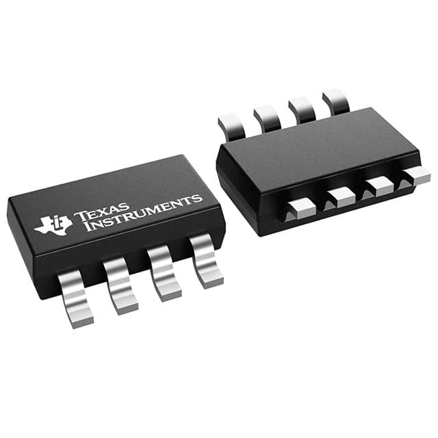
- Part No.:
- INA186A2QDDFRQ1
- Manufacturer:
- Texas Instruments
- Category:
- Instrumentation, Op Amps, Buffer Amps
- Package:
- SOT-23-8 Thin, TSOT-23-8
- Datasheet:
-
 INA186A2QDDFRQ1.pdf
- Description:
- AEC-Q100, 40-V, BIDIRECTIONAL, H
- Quantity:
- Payment:

- Shipping:

Inventory:2,979
Please send an inquiry. Send us your inquiry, and we will respond immediately.
Product details
Overview
INA186A2QDDFRQ1 from Texas Instruments is an AEC-Q100 Grade 1 automotive current-sense amplifier optimized for bidirectional, high-precision monitoring of battery currents in 12-V systems. It delivers 50 V/V fixed gain, ±1% max gain error, ±50 µV max offset voltage, and operates from 1.7 V to 5.5 V supply with 48 µA typical quiescent current - enabling accurate microamp-range sensing in body control modules and BMS.
For engineers reviewing the INA186A2QDDFRQ1 datasheet, INA186A2QDDFRQ1 pinout, INA186A2QDDFRQ1 application, or INA186A2QDDFRQ1 equivalent, key selection criteria include its 40-V common-mode range (–0.2 V to +40 V), 120 dB minimum CMRR, ENABLE pin for low-power duty cycling, REF pin for bidirectional operation, and DDF (8-pin SOT-23) package with validated pinout and thermal performance up to +125°C.
Technical Context
The INA186A2QDDFRQ1 uses a capacitively coupled front-end architecture to achieve high common-mode rejection (120 dB min) while supporting input voltages up to 42 V absolute maximum - critical for direct connection to automotive 12-V battery rails. Its zero-drift topology ensures stable offset (±50 µV max) and ultra-low drift (0.5 µV/°C max) across –40°C to +125°C.
It integrates an ENABLE pin (pin 2) that reduces supply current to ≤100 nA in shutdown, places OUT in high-impedance state, and supports periodic current sampling without external switches. The REF pin (pin 3) enables true bidirectional sensing by offsetting the output voltage, allowing detection of current flow direction relative to a user-defined reference.
Key Specifications
| Parameter | Value and Actual Design Meaning |
|---|---|
| Gain | 50 V/V - fixed ratio; scales shunt voltage drop linearly for precise current calculation with minimal calibration. |
| Common-mode Range | –0.2 V to +40 V - supports both high-side and low-side sensing on 12-V battery rails independent of supply voltage. |
| Input Bias Current | 500 pA typical - enables use of high-value sense resistors for µA-level current resolution without significant error. |
| Offset Voltage | ±50 µV maximum - ensures accuracy at light loads and allows smaller shunt resistors to reduce power loss. |
| Quiescent Current | 48 µA typical (enabled), ≤100 nA (disabled) - extends battery life in telematics and eCall systems requiring intermittent monitoring. |
| CMRR | 120 dB minimum - rejects noise from noisy battery transients, maintaining measurement integrity in harsh automotive environments. |
| Bandwidth | 37 kHz - sufficient for DC and slow-varying load currents in BCM and BMS applications. |
Pinout & Package
The INA186A2QDDFRQ1 is packaged in an 8-pin SOT-23 (DDF) variant measuring 2.90 mm × 1.60 mm, qualified for automotive Grade 1 (–40°C to +125°C) operation and featuring wettable flanks for automated optical inspection.
| Pin/Terminal | Circuit Role | Design Meaning |
|---|---|---|
| VS (Pin 1) | Power supply input | Accepts 1.7 V to 5.5 V; powers internal amplifiers and ENABLE logic; must be bypassed with ≥0.1 µF capacitor. |
| ENABLE (Pin 2) | Digital enable control | Drives device ON (≥0.7×VS) or OFF (≤0.3×VS); reduces IQ to ≤100 nA and places OUT in high-Z state when disabled. |
| REF (Pin 3) | Bidirectional reference input | Accepts GND to VS; sets output center point for bidirectional sensing; requires buffered source for optimal CMRR. |
| GND (Pin 4) | Analog ground reference | Return path for internal circuitry; must be connected to system ground with low-impedance trace near device. |
| OUT (Pin 5) | Analog voltage output | Delivers VOUT = GAIN × (VIN+ − VIN−) + VREF; rail-to-rail swing (GND +1 mV to VS −40 mV) maximizes dynamic range at low supply. |
| IN− (Pin 8) | Negative current-sense input | Connects to load side (high-side) or ground side (low-side) of shunt; withstands −0.2 V to +40 V common-mode. |
| IN+ (Pin 7) | Positive current-sense input | Connects to bus side (high-side) or load side (low-side) of shunt; same common-mode tolerance as IN−. |
| NC (Pin 6) | No-connect terminal | No internal connection; may be left floating, grounded, or tied to VS without affecting operation. |
Key Features
| Feature | Design Value |
|---|---|
| AEC-Q100 Grade 1 qualification | Validated for automotive operation from –40°C to +125°C ambient, including temperature cycling, humidity, and vibration stress. |
| Bidirectional sensing with REF pin | Enables detection of current direction (charge vs. discharge) in 12-V BMS using externally applied reference voltage. |
| Ultra-low input bias current (500 pA typ) | Permits use of ≥10 kΩ sense resistors for sub-µA current resolution without loading error or thermal drift impact. |
| Functional safety documentation support | Includes FIT rate data, failure mode analysis, and diagnostic coverage guidance for ISO 26262 ASIL-B system integration. |
| Rail-to-rail output swing | Delivers usable output range down to GND +1 mV and up to VS −40 mV - critical for accuracy with 1.8-V microcontroller ADCs. |
Applications
| Body Control Module (BCM) | Telematics Control Unit |
|---|---|
Use Scenario: Monitoring power distribution to door locks, lighting, and window actuators in modern vehicle architectures. IC Role / Device Role / Timing Role: High-side current-sense amplifier measuring load currents on 12-V switched outputs with ±1% gain accuracy and 40-V survivability. Use Value: Detects open-circuit, short-circuit, and overcurrent faults before fuse activation, enabling predictive diagnostics and reduced warranty claims. | Use Scenario: Measuring standby and active current consumption of LTE/C-V2X modems and GNSS receivers during vehicle ignition-off states. IC Role / Device Role / Timing Role: Low-quiescent-current (48 µA) bidirectional monitor capturing battery drain profiles across sleep/wake cycles. Use Value: Extends parked vehicle battery life by validating modem power states and identifying parasitic draw exceeding OEM thresholds. |
| Emergency Call (eCall) | 12-V Battery Management System (BMS) |
Use Scenario: Verifying power availability and health of backup power path for automatic crash notification systems after main battery disconnect. IC Role / Device Role / Timing Role: Unidirectional current monitor on supercapacitor or secondary battery charging path with ±50 µV offset stability. Use Value: Ensures reliable eCall activation under low-temperature conditions where battery voltage sag would otherwise mask fault conditions. | Use Scenario: Bidirectional charge/discharge current monitoring in start-stop and mild-hybrid 12-V systems with regenerative braking feedback. IC Role / Device Role / Timing Role: REF-pin-enabled bidirectional amplifier measuring net current flow with 50 V/V gain and 120 dB CMRR against alternator ripple. Use Value: Enables accurate state-of-charge estimation and battery health tracking without separate high-side/low-side sensor hardware. |
Equivalent & Alternatives
The following parts are listed as comparable options for similar current-sense amplifier applications.
| Alternative Part | Technical Difference | Application Difference | Selection Advice |
|---|---|---|---|
| INA240A1QDRQ1 | Higher bandwidth (400 kHz), higher gain error (±0.2%), no ENABLE pin, 80-V common-mode range | Optimized for motor phase current sensing; lacks low-IQ shutdown for battery-sensitive applications | Select when fast transient response is required and continuous monitoring is acceptable. |
| MAX40056ATA+T | Lower offset (±12 µV), no REF pin, 65-V common-mode, 1.8-V to 5.5-V supply, no AEC-Q100 qualification | Targeted at industrial/commercial BMS; not certified for automotive production use | Select only for non-automotive designs where AEC-Q100 compliance is not mandated. |
Compared with INA240A1QDRQ1 and MAX40056ATA+T, the INA186A2QDDFRQ1 uniquely balances AEC-Q100 Grade 1 qualification, ENABLE-driven ultra-low power (≤100 nA), and REF-based bidirectional capability - making it the only option among the three qualified for automotive telematics and eCall systems requiring intermittent, direction-aware battery monitoring.
Availability
INA186A2QDDFRQ1 is available at Aetrix Electronics and suitable for body control modules, telematics units, emergency call systems, and 12-V battery management systems requiring stable component supply across automotive production lifecycles.
Supply support for INA186A2QDDFRQ1 includes scheduled delivery planning, volume procurement assistance, BOM continuity management, traceable sourcing, and lifecycle availability coordination for OEM customers, industrial embedded developers, connected-device designers, and electronics production programs.
Manufacturer
Texas Instruments is a global semiconductor leader delivering analog and embedded processing solutions, with deep expertise in precision signal chain and automotive-qualified components.
The INA186-Q1 product line was designed specifically for high-accuracy, low-power current sensing in automotive 12-V battery-connected systems - emphasizing AEC-Q100 reliability, bidirectional capability, and compatibility with microamp-level sensing requirements.
FAQ
What is the maximum common-mode voltage the INA186A2QDDFRQ1 can withstand?
The INA186A2QDDFRQ1 supports a continuous common-mode input range of –0.2 V to +40 V and has an absolute maximum rating of 42 V on IN+ and IN– pins. This makes it suitable for direct connection to automotive 12-V battery rails with margin for load-dump transients. Operation beyond +40 V or below –0.2 V violates recommended conditions and may degrade accuracy or reliability.
Does the INA186A2QDDFRQ1 support bidirectional current sensing, and how is it implemented?
Yes, the INA186A2QDDFRQ1 supports bidirectional current sensing via its dedicated REF pin (Pin 3). Applying a reference voltage (e.g., VS/2) to REF centers the output voltage; positive differential input produces VOUT > VREF, while negative differential input yields VOUT < VREF. This configuration is enabled only in the DDF package and requires buffered REF drive to maintain CMRR.
What is the purpose of the ENABLE pin on the INA186A2QDDFRQ1, and what happens when it is asserted low?
The ENABLE pin (Pin 2) controls power state: driving it to ≥0.7×VS enables normal operation, while pulling it to ≤0.3×VS disables the device. In disable mode, the INA186A2QDDFRQ1 draws ≤100 nA quiescent current and places the OUT pin in high-impedance state - eliminating loading on downstream circuits and enabling power-gating in battery-constrained systems like eCall modules.
Can the INA186A2QDDFRQ1 be used with a 1.8-V supply, and what is its output swing capability at that voltage?
Yes, the INA186A2QDDFRQ1 operates from 1.7 V to 5.5 V, including 1.8-V systems. At 1.8 V, its output swings from GND +1 mV to VS –40 mV (i.e., 1.76 V), delivering >97% of full-scale range - essential for maximizing resolution when interfacing with low-voltage microcontroller ADCs in modern automotive ECUs.
How does the low input bias current of 500 pA benefit system design with the INA186A2QDDFRQ1?
The 500 pA typical input bias current minimizes error from sense resistor self-heating and enables use of high-value shunts (e.g., 10 kΩ) for detecting currents as low as 100 nA. It also permits RC input filtering without degrading accuracy - unlike conventional amplifiers where bias current interacts with filter impedance to create offset errors - improving noise immunity in electrically noisy automotive environments.
INA186A2QDDFRQ1 Specifications
- Product attributes
- Attribute value
- Manufacturer:
- Texas Instruments
- Series:
- -
- Package/Case:
- SOT-23-8 Thin, TSOT-23-8
- Packaging:
- Tape & Reel (TR)
- Product Status:
- Active
- Amplifier Type:
- Current Sense
- Number of Circuits:
- 1
- Output Type:
- Rail-to-Rail
- Slew Rate:
- 0.3V/µs
- Gain Bandwidth Product:
- -
- -3db Bandwidth:
- 37 kHz
- Current - Input Bias:
- 500 pA
- Voltage - Input Offset:
- 3 µV
- Current - Supply:
- 48µA
- Current - Output / Channel:
- -
- Voltage - Supply Span (Min):
- 1.7 V
- Voltage - Supply Span (Max):
- 5.5 V
- Operating Temperature:
- -40°C ~ 125°C (TA)
- Grade:
- Automotive
- Qualification:
- AEC-Q100
- Mounting Type:
- Surface Mount
- Supplier Device Package:
- TSOT-23-8
INA186A2QDDFRQ1 FAQ
1.How can I place an order for INA186A2QDDFRQ1 through Aetrix?
Please submit a Request for Quotation (RFQ) for INA186A2QDDFRQ1 on Aetrix. Our sales agent will provide a competitive quotation and guide you through the order confirmation once you accept the terms.
2.Are the price and stock information for INA186A2QDDFRQ1 reliable?
The price and inventory of INA186A2QDDFRQ1 are updated periodically and may fluctuate due to market conditions. Stock and pricing data are typically refreshed every 24 hours. Quotation validity for INA186A2QDDFRQ1 is usually 5 days.
3.What payment methods are accepted for INA186A2QDDFRQ1?
We accept Wire Transfer, PayPal, Credit Card, Western Union, MoneyGram, and Escrow for INA186A2QDDFRQ1 transactions.
Note: Certain payment methods may incur a processing fee.
4.How is shipping managed for INA186A2QDDFRQ1?
INA186A2QDDFRQ1 orders can be shipped via leading logistics carriers, including DHL, UPS, FedEx, TNT, or Registered Mail.
Once your INA186A2QDDFRQ1 order is processed, you will receive an email with the shipment details and tracking number.
Note: Tracking information may take up to 24 hours to appear. Express delivery typically takes 3–5 business days.
5.How can I obtain technical support or documentation for INA186A2QDDFRQ1?
For technical support, including INA186A2QDDFRQ1 datasheets, pinout diagrams, or application guidance, please contact our engineering support team. They can provide detailed documentation and assistance for your INA186A2QDDFRQ1 requirements.
6.How does Aetrix verify that INA186A2QDDFRQ1 is sourced from the original manufacturer or authorized distributors?
All INA186A2QDDFRQ1 products on Aetrix are procured from qualified distributors and authorized channels. Our dedicated quality assurance team conducts strict verification, including traceability checks and, if necessary, third-party testing. This ensures that INA186A2QDDFRQ1 meets industry standards.
7.What is the process for return or replacement of INA186A2QDDFRQ1?
All INA186A2QDDFRQ1 units undergo pre-shipment inspection (PSI). If there is an issue with INA186A2QDDFRQ1, returns or replacements are accepted under the following conditions:
1.Quantity discrepancies, incorrect items, or visible external defects (such as breakage or corrosion), acknowledged by Aetrix.
2.The issue is reported within 90 days of delivery.
3.The INA186A2QDDFRQ1 part is unused and in its original packaging.
Return procedure for INA186A2QDDFRQ1:
1.Submit a request within 90 days.
2.Obtain a Return Material Authorization (RMA) from Aetrix.
INA186A2QDDFRQ1 Tags

-
LM358DT
STMicroelectronics

-
LM358DR
Texas Instruments
-
LM2904DR
Texas Instruments
-
LM358ADR
Texas Instruments

-
LM2904DGKR
Texas Instruments

-
LM324DR
Texas Instruments

-
MCP6006T-E/OT
Microchip Technology
-
MCP6006UT-E/OT
Microchip Technology

-
LM324PWR
Texas Instruments
-
LM2902PWR
Texas Instruments
-
LM2902DR
Texas Instruments

-
LM358P
Texas Instruments
Tech Hub

A practical engineering guide to 3.3V and 5V logic compatibility, input thresholds, resistor dividers, translator ICs, MOSFET level shifting, I2C pull-ups, timing limits and power-sequencing risks.

The 74HC595 uses push-pull logic outputs, while the TPIC6B595 uses 50 V open-drain DMOS sinks for higher-power loads. This guide compares timing, current limits, 3.3 V interfacing, load wiring, thermal…

The 74HC595 converts serial data into eight stable parallel outputs. This guide covers pin functions, shift and storage timing, OE and MR behavior, drive-current limits, cascading, voltage compatibilit…

A technical comparison of level-sensitive latches and edge-triggered flip-flops, covering timing windows, setup and hold limits, master–slave operation, time borrowing, race-through, HDL inference and…

A D latch stores one bit while Enable controls when data can pass. This reference covers gate-level operation, truth tables, transparency, setup and hold timing, LE versus OE, common ICs and practical …

An SR latch stores one bit through cross-coupled feedback. This engineering reference covers NOR and NAND implementations, truth tables, forbidden-state recovery, gated operation, switch debouncing, fa…

Latch circuits retain one bit through feedback. This technical reference covers SR and D latches, truth tables, transparency, timing limits, latch-versus-flip-flop behavior, applications and common log…

An engineering guide to LED driver operation, constant-current and constant-voltage outputs, linear and switching topologies, dimming, IC selection, calculations, replacement compatibility, and fault c…

Operational amplifier guide covering op amp basics, feedback, ideal vs real op amps, common configurations, buffer circuits, offset, bias current, gain-bandwidth, slew rate, rail-to-rail limits and sel…

Jumper cables guide covering safe connection order, red and black clamp placement, final ground connection, cable gauge, length, clamp quality, copper vs CCA cables, jump starter comparison and battery…


