
 My Inquiry
 My Account


Infineon Technologies IR2177SPBF
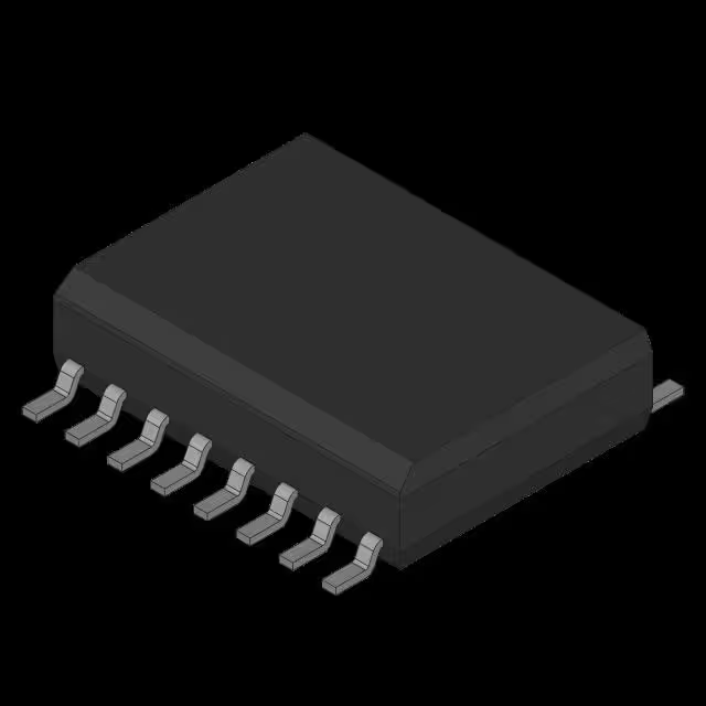
- Part No.:
- IR2177SPBF
- Manufacturer:
- Infineon Technologies
- Category:
- Current Regulation/Management
- Package:
- 16-SOIC (0.295", 7.50mm Width)
- Datasheet:
-
 IR2177SPBF.pdf
- Description:
- IC CURRENT SENSE 0.2% 16SOIC
- Quantity:
- Payment:

- Shipping:

Inventory:1,890
Please send an inquiry. Send us your inquiry, and we will respond immediately.
Product details
Overview
IR2177SPBF from Infineon Technologies is a high-voltage, single-phase current sensor IC for AC motor drives, featuring floating channel operation up to 600 V, <7.5 µs sensing latency at 20 kHz, ratiometric analog output (OUT), digital PWM output (PO), and fast overcurrent detection (OC) with ±470 mV threshold. It interfaces with external shunt resistors and supports bootstrap power supplies in IGBT gate driver circuits.
For engineers reviewing the IR2177SPBF datasheet, IR2177SPBF pinout, IR2177SPBF application, or IR2177SPBF equivalent, this device is selected for precision phase current sensing in variable-frequency drives, where low group delay, high common-mode rejection (100 dB for OUT), and synchronous sampling under high dV/dt noise are critical design requirements.
Technical Context
The IR2177SPBF implements a synchronous sampling measurement system that converts differential shunt voltage (±250 mV) into time-interval-modulated outputs-both PWM (PO) and ratiometric analog (OUT)-with precise ripple rejection and minimal group delay (~4 µs). Its floating channel architecture enables direct high-side sensing referenced to VS, supporting bootstrap-fed half-bridge topologies.
It features dual output formats: PO delivers gain-stable PWM (−40.5 %/V typ.) with CMRR of 0.2 m%/V against VS offset, while OUT provides analog output with 0.3–0.7% linearity and PSRR of 30–100 dB. OC signal asserts within 2.7–4.7 µs for IGBT protection, with internal hysteresis and open-collector drive.
Key Specifications
| Parameter | Value and Actual Design Meaning |
|---|---|
| VOFFSET (max) | 600 V - Enables direct high-side current sensing in 600 V-class motor inverters without level-shifting circuitry. |
| Sensing latency | <7.5 µs @20 kHz - Ensures timely current feedback for closed-loop FOC control with minimal phase lag. |
| Throughput | 40 ksample/sec - Supports real-time current acquisition synchronized to asymmetrical PWM up to 20 kHz. |
| OC threshold | ±470 mV - Configurable overcurrent trip point matching typical shunt-based fault detection in IGBT modules. |
| CMRR (OUT) | 100 dB @600 V - Rejects high dV/dt noise from switching nodes, preserving analog accuracy in noisy half-bridge environments. |
| Bootstrap supply range | 8–20 V - Compatible with standard bootstrap capacitor charging circuits using 12–15 V gate drive rails. |
| Analog output gain | −20% to +20% of VR (VR = VRH–VRL) - Ratiometric scaling ensures immunity to reference voltage drift in DSP A/D interfaces. |
Pinout & Package
IR2177SPBF is housed in an 8-pin SOIC package (SOIC-8, 150 mil width) with creepage-optimized layout for high-voltage isolation. Pin functions are validated per Infineon PD60233 revB datasheet.
| Pin/Terminal | Circuit Role | Design Meaning |
|---|---|---|
| VIN+, VIN− | Differential high-side current sense inputs | Accept ±250 mV shunt voltage; referenced to VS, not ground-enables true high-side sensing. |
| VS | High-side floating ground | Return node for high-side circuitry; tracks switching node potential up to 600 V offset from VSS. |
| VB | High-side floating supply | Provides bias for internal high-side circuitry; requires bootstrap or isolated supply (8–20 V). |
| VCC | Low-side logic supply | Powers internal logic, OC, PO, and OUT drivers; operates from 8–20 V referenced to VSS. |
| SYNC | Sampling synchronization input | Edge-triggered input (Schmitt-triggered, 0.8–2.2 V thresholds) aligning conversion timing to PWM period. |
| OUT | Ratiometric analog output | Voltage output proportional to sensed current, scaled by VRH–VRL reference; drives DSP A/D directly. |
| PO | Digital PWM output | Time-interval modulated signal (4–20 kHz) with −40.5 %/V gain; used for microcontroller timer capture. |
| OC | Open-collector overcurrent flag | Active-low fault signal with 2.7–4.7 µs response; pulls down via internal 25–75 Ω on-resistance. |
Key Features
| Feature | Design Value |
|---|---|
| Synchronous sampling architecture | Eliminates aliasing in PWM-synchronized current loops by locking conversion to SYNC edge-critical for FOC stability. |
| High dV/dt immunity | Rated for 50 V/ns slew rate and 600 V offset-maintains accuracy during IGBT turn-on/off transients. |
| Dual-format output (PO + OUT) | Enables flexible host interface: PO for high-speed timer capture, OUT for precision A/D-no external ADC or comparator needed. |
| Fast OC response with debouncing | 2.7–4.7 µs detection + built-in 0.5 µs reset delay prevents false trips from transient noise spikes. |
| Ratiometric analog output | Output scales with VRH–VRL reference voltage-removes dependency on absolute VCC stability in DSP systems. |
Applications
| Industrial Variable-Frequency Drive | Appliance Motor Control (Washing Machine) |
|---|---|
Use Scenario: Closed-loop field-oriented control of 3-phase induction motors in HVAC compressors and pumps. IC Role / Device Role / Timing Role: High-side phase current sensor providing synchronized, low-latency feedback to DSP for torque regulation. Use Value: <7.5 µs latency and 100 dB CMRR ensure accurate current reconstruction despite 600 V bus switching noise. | Use Scenario: Real-time current monitoring in inverter-driven drum motors for spin cycle balancing and overload protection. IC Role / Device Role / Timing Role: Single-phase current interface converting shunt voltage to both PWM and analog outputs for MCU dual-path processing. Use Value: Dual-output capability allows simultaneous high-speed fault detection (via OC/PO) and precision torque estimation (via OUT). |
| Electric Bicycle Motor Controller | Small AC Servo Amplifier |
Use Scenario: Compact, cost-sensitive 48–72 V BLDC motor controllers requiring integrated overcurrent protection. IC Role / Device Role / Timing Role: Current sensing element interfacing with bootstrap-gated MOSFET half-bridges; OC output directly disables gate drivers. Use Value: Open-collector OC with 25–75 Ω on-resistance enables direct connection to standard gate driver enable pins without external pull-ups. | Use Scenario: Precision position/speed control in CNC axis drives using sinusoidal commutation. IC Role / Device Role / Timing Role: High-fidelity current digitization block feeding FPGA-based current loop with sub-microsecond timing alignment. Use Value: Synchronous sampling and <4 µs group delay preserve phase coherence between current samples and PWM edges-essential for low-distortion sine-wave synthesis. |
Equivalent & Alternatives
The following parts are listed as comparable options for similar high-voltage current sensing applications.
| Alternative Part | Technical Difference | Application Difference | Selection Advice |
|---|---|---|---|
| ACS724LLCTR-20AU-T | Galvanically isolated Hall-effect sensor; 20 A range; fixed 1.2 V output; no PWM output or SYNC input. | Lower voltage rating (480 V max); no floating channel; unsuitable for direct high-side shunt sensing in 600 V inverters. | Choose when isolation is mandatory and bandwidth ≤20 kHz suffices; avoid where synchronous sampling or bootstrap compatibility is required. |
| INA240A1QPWRQ1 | High-side current sense amplifier; 80 V common-mode; 120 kHz bandwidth; analog-only output; no OC or PWM. | Limited to ≤80 V offset; requires external comparator and timing logic for overcurrent; no built-in SYNC alignment. | Prefer for lower-voltage DC systems (<80 V) needing high-precision analog output; not viable for 600 V motor phase sensing. |
Compared with ACS724LLCTR-20AU-T and INA240A1QPWRQ1, IR2177SPBF uniquely integrates synchronous sampling, dual-format output, 600 V floating operation, and fast OC in one SOIC-8 package-making it irreplaceable for compact, high-performance AC motor drives requiring tight timing alignment and noise resilience.
Availability
IR2177SPBF is available at Aetrix Electronics and suitable for industrial variable-frequency drives, appliance motor controllers, and e-bike power stages requiring stable component supply, long-term lifecycle support, and traceable sourcing for high-reliability production.
Supply support for IR2177SPBF includes scheduled delivery planning, volume procurement assistance, BOM continuity management, traceable sourcing, and lifecycle availability coordination for OEM customers, industrial embedded developers, connected-device designers, and electronics production programs.
Manufacturer
Infineon Technologies is a German semiconductor manufacturer specializing in power management, automotive electronics, and industrial control ICs, with leadership in high-voltage analog and mixed-signal solutions.
The IR2177SPBF belongs to Infineon's high-voltage current sensor product line, designed specifically to replace discrete op-amp/comparator solutions in AC motor drives-delivering integrated timing alignment, noise immunity, and dual-output flexibility in a single chip.
FAQ
What is the maximum allowable dV/dt at the VS pin?
The IR2177SPBF is rated for 50 V/ns dV/dt at the VS pin under recommended operating conditions. This specification ensures reliable operation during fast IGBT or MOSFET switching transitions in 600 V motor inverters, preventing false triggering or latch-up due to capacitive coupling into the floating domain.
Can IR2177SPBF operate with a 5 V VCC supply?
No-IR2177SPBF requires VCC between 8 V and 20 V. A 5 V supply falls below the minimum operating voltage and will prevent proper internal biasing of logic and output drivers, resulting in undefined behavior or failure to assert OC/PO signals.
How does the ratiometric analog output (OUT) scale with reference voltage?
The OUT voltage is ratiometric to VR = VRH – VRL, with nominal gain of −20% to +20% of VR. For example, with VR = 3 V, OUT ranges from −0.6 V to +0.6 V for ±250 mV input-ensuring output accuracy remains tied to reference stability rather than VCC or internal bandgap drift.
Is external filtering required on the SYNC input?
No external filtering is required-the SYNC input includes an internal Schmitt trigger with 0.2 V hysteresis and a 6–12 kΩ internal pull-down resistor. Clean TTL- or CMOS-level edges (0.8 V low / 2.2 V high) directly from MCU timers are sufficient for reliable synchronization.
IR2177SPBF Specifications
- Product attributes
- Attribute value
- Manufacturer:
- Infineon Technologies
- Series:
- -
- Package/Case:
- 16-SOIC (0.295", 7.50mm Width)
- Packaging:
- Tube
- Product Status:
- Obsolete
- Function:
- Current Sense
- Sensing Method:
- -
- Accuracy:
- ±0.2%
- Voltage - Input:
- 8V ~ 20V
- Current - Output:
- -
- Operating Temperature:
- -40°C ~ 125°C
- Grade:
- -
- Qualification:
- -
- Mounting Type:
- Surface Mount
- Supplier Device Package:
- 16-SOIC
IR2177SPBF FAQ
1.How can I place an order for IR2177SPBF through Aetrix?
Please submit a Request for Quotation (RFQ) for IR2177SPBF on Aetrix. Our sales agent will provide a competitive quotation and guide you through the order confirmation once you accept the terms.
2.Are the price and stock information for IR2177SPBF reliable?
The price and inventory of IR2177SPBF are updated periodically and may fluctuate due to market conditions. Stock and pricing data are typically refreshed every 24 hours. Quotation validity for IR2177SPBF is usually 5 days.
3.What payment methods are accepted for IR2177SPBF?
We accept Wire Transfer, PayPal, Credit Card, Western Union, MoneyGram, and Escrow for IR2177SPBF transactions.
Note: Certain payment methods may incur a processing fee.
4.How is shipping managed for IR2177SPBF?
IR2177SPBF orders can be shipped via leading logistics carriers, including DHL, UPS, FedEx, TNT, or Registered Mail.
Once your IR2177SPBF order is processed, you will receive an email with the shipment details and tracking number.
Note: Tracking information may take up to 24 hours to appear. Express delivery typically takes 3–5 business days.
5.How can I obtain technical support or documentation for IR2177SPBF?
For technical support, including IR2177SPBF datasheets, pinout diagrams, or application guidance, please contact our engineering support team. They can provide detailed documentation and assistance for your IR2177SPBF requirements.
6.How does Aetrix verify that IR2177SPBF is sourced from the original manufacturer or authorized distributors?
All IR2177SPBF products on Aetrix are procured from qualified distributors and authorized channels. Our dedicated quality assurance team conducts strict verification, including traceability checks and, if necessary, third-party testing. This ensures that IR2177SPBF meets industry standards.
7.What is the process for return or replacement of IR2177SPBF?
All IR2177SPBF units undergo pre-shipment inspection (PSI). If there is an issue with IR2177SPBF, returns or replacements are accepted under the following conditions:
1.Quantity discrepancies, incorrect items, or visible external defects (such as breakage or corrosion), acknowledged by Aetrix.
2.The issue is reported within 90 days of delivery.
3.The IR2177SPBF part is unused and in its original packaging.
Return procedure for IR2177SPBF:
1.Submit a request within 90 days.
2.Obtain a Return Material Authorization (RMA) from Aetrix.
IR2177SPBF Tags
.jpg)
-
PSSI2021SAY,115
Nexperia USA Inc.

-
BCR401RE6327HTSA1
Infineon Technologies

-
INA199B2DCKR
Texas Instruments
-
INA199A1DCKR
Texas Instruments
-
INA199B1DCKR
Texas Instruments
-
NSI45015WT1G
onsemi
-
NSI45020T1G
onsemi
-
NSI45030AT1G
onsemi
-
NSI45025AT1G
onsemi
-
NSI45020AT1G
onsemi
-
NSI50010YT1G
onsemi
-
LM334Z/NOPB
Texas Instruments
Tech Hub

Jumper cables guide covering safe connection order, red and black clamp placement, final ground connection, cable gauge, length, clamp quality, copper vs CCA cables, jump starter comparison and battery…

LDO regulator guide covering low dropout voltage, power dissipation, thermal design, PSRR, output noise, capacitor stability, adjustable LDO circuits, LDO vs buck converter and datasheet selection chec…

Conditional Access Module guide covering CAM meaning, CI/CI+ interface, smart card authorization, DVB security workflow, TV and set-top box compatibility, internal electronics, ESD protection, connecto…

Guide to electronic component obsolescence covering EOL risk, PCN/PDN notices, last-time buy planning, replacement options, form-fit-function validation, counterfeit risk and BOM lifecycle management.

18650 battery guide covering lithium-ion cell basics, 3.6V/3.7V voltage, 4.2V charging, mAh and Wh capacity, protected cells, chargers, BMS, series-parallel packs, holders, welding and sourcing checks.…

Hall effect sensor guide covering working principle, linear and digital sensors, Arduino circuits, current sensing, speed detection, automotive applications, A3144 examples, signal filtering and datash…

Product Change Notification guide for electronic components, covering PCN meaning, PCN vs PDN/EOL, common change types, risk levels, form-fit-function review, engineering validation, BOM control, LTB/L…

A practical guide to blend door actuators, covering HVAC function, symptoms, location, AC and heater issues, reset and calibration, replacement cost, electrical diagnosis, compatibility checks, and rep…

Engineering guide to Raspberry Pi alternatives, covering chip-level differences, Orange Pi, ROCK, Jetson, Banana Pi, NanoPi, Compute Module, Pico, GPIO, camera, HAT compatibility, and replacement risks…

Engineering guide to dynamic load response testing for high-current buck converters, covering load step setup, slew rate, Vcore undershoot, overshoot, recovery time, probe location, output capacitors a…


