
 My Inquiry
 My Account


Renesas IS82C54Z
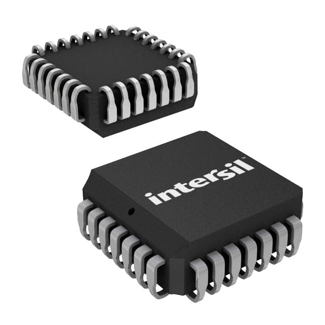
- Part No.:
- IS82C54Z
- Manufacturer:
- Renesas
- Category:
- Programmable Timers and Oscillators
- Package:
- 28-LCC (J-Lead)
- Datasheet:
-
 IS82C54Z.pdf
- Description:
- IC OSC PROG TIMER 8MHZ 28PLCC
- Quantity:
- Payment:

- Shipping:

Inventory:3,523
Please send an inquiry. Send us your inquiry, and we will respond immediately.
Product details
Overview
IS82C54Z from Intersil is a CMOS programmable interval timer IC with three independent 16-bit counters, 8MHz clock input capability, TTL-compatible I/O, and operation over –40°C to +85°C. It serves as a system timing peripheral in legacy x86 embedded controllers for real-time clock generation, event counting, and programmable rate control.
For engineers reviewing the IS82C54Z datasheet, IS82C54Z pinout, IS82C54Z application, or IS82C54Z equivalent, this page delivers verified functional identity, validated PDIP-24 pin mapping, confirmed -40°C to +85°C industrial temperature rating, exact AC/DC electrical specs per FN2970 Rev 6.00, and two documented alternative parts with mode-level compatibility and package-aware selection guidance.
Technical Context
The IS82C54Z implements three fully independent 16-bit synchronous down counters, each configurable via software-written control words into one of six operational modes (Mode 0–5), supporting binary or BCD counting. Its read/write logic decodes A0/A1 address lines to select Counter 0/1/2 or the Control Word Register, with CS, RD, and WR enabling standard microprocessor bus interfacing.
It features a status read-back command that latches count value, output state, null-count flag, and programmed mode-enabling non-intrusive runtime monitoring. Static CMOS design ensures low ICCSB = 10µA standby current while maintaining full TTL compatibility and single +5V supply operation across its specified temperature range.
Key Specifications
| Parameter | Value and Actual Design Meaning |
|---|---|
| Counter Count Width | 16-bit presettable synchronous down counter per channel; supports precise timing intervals up to 65,535 clock cycles. |
| Max Clock Input Frequency | 8 MHz; defines maximum resolution for timebase generation and event counting without external prescaling. |
| Operating Voltage | +4.5 V to +5.5 V; compatible with standard 5V TTL/CMOS logic rails and legacy microprocessor buses. |
| Temperature Range | –40°C to +85°C; qualified for industrial embedded systems including motor controllers and PLC I/O modules. |
| Standby Current | 10 µA at VCC = 5.5 V; enables low-power sleep-mode operation in battery-backed or energy-sensitive applications. |
| Output Drive | TTL-compatible VOH ≥ 3.0 V (IOH = –2.5 mA), VOL ≤ 0.4 V (IOL = +2.5 mA); directly interfaces with 74LS/74HC logic and microcontroller GPIOs. |
| Package Type | 24-pin PDIP (Plastic Dual In-line Package); through-hole mountable with E24.6 footprint, RoHS-compliant Pb-free plus anneal finish. |
Pinout & Package
IS82C54Z is housed in a 24-lead plastic dual in-line package (PDIP) with 0.6-inch body width and E24.6 mechanical drawing compliance. Pin 12 and Pin 24 are dedicated GND and VCC respectively; all digital I/O pins are TTL-compatible and three-state capable.
| Pin/Terminal | Circuit Role | Design Meaning |
|---|---|---|
| D0–D7 | Data Bus I/O | Bi-directional 8-bit data interface; connects directly to CPU data bus for control word and count transfers. |
| CLK 0 / CLK 1 / CLK 2 | Counter Clock Inputs | Independent asynchronous clock inputs per counter; rising-edge triggered, support up to 8 MHz. |
| GATE 0 / GATE 1 / GATE 2 | Counter Enable Inputs | Level-sensitive gate control; high enables counting, low freezes counter and holds OUT state. |
| OUT 0 / OUT 1 / OUT 2 | Counter Output Signals | Active-high or mode-defined output waveforms; used for interrupt assertion, waveform generation, or feedback control. |
| A0, A1 | Address Select Inputs | Selects target register: 00=Counter 0, 01=Counter 1, 10=Counter 2, 11=Control Word Register. |
| CS | Chip Select | Active-low enable; must be asserted for RD/WR operations to affect internal registers. |
| RD, WR | Read/Write Strobes | Active-low bus control signals; synchronized with CS and A0/A1 to execute register access. |
| VCC, GND | Power Supply | +5 V DC supply (Pin 24) and ground return (Pin 12); requires local 0.1 µF decoupling capacitor. |
Key Features
| Feature | Design Value |
|---|---|
| Status Read-Back Command | Enables software inspection of counter output state, null-count flag, and active mode without halting operation. |
| Six Programmable Timer Modes | Supports interrupt-on-terminal-count (Mode 0), programmable one-shot (Mode 1), rate generator (Mode 2), square-wave generator (Mode 3), software-triggered strobe (Mode 4), and hardware-triggered strobe (Mode 5). |
| Binary or BCD Counting | Configurable per-counter numeric format; BCD enables direct decade-based timing (e.g., 100 ms, 1 s) without software conversion. |
| Three Independent Counters | Enables concurrent timing tasks-e.g., real-time clock (Counter 0), event counter (Counter 1), and PWM generator (Counter 2)-on a single IC. |
| Static CMOS Architecture | Delivers 10 µA standby current and full 5V TTL compatibility while eliminating dynamic power concerns of NMOS predecessors. |
Applications
| Industrial Motor Control | Legacy x86 System Timing |
|---|---|
|
Use Scenario: Precise speed regulation and position feedback in stepper/servo drives using pulse-width modulation and encoder counting. IC Role / Device Role / Timing Role: IS82C54Z acts as a programmable rate generator and event counter, synchronizing motor phase timing and capturing quadrature encoder pulses. Use Value: Enables deterministic, software-configurable timing without CPU overhead-critical for closed-loop motion control in PLCs and CNC systems. |
Use Scenario: Real-time clock (RTC), system timer tick, and DMA request generation in 80C86/80C286-based industrial computers. IC Role / Device Role / Timing Role: IS82C54Z serves as a peripheral timer co-processor, providing accurate timekeeping and periodic interrupts independent of main CPU execution. Use Value: Offloads timing-critical functions from the host processor, improving deterministic response and reducing firmware complexity in legacy embedded BIOS and RTOS environments. |
| Programmable Power Sequencing | Test Equipment Signal Generation |
|
Use Scenario: Controlled ramp-up/ramp-down of multiple voltage rails in FPGA or ASIC power management subsystems. IC Role / Device Role / Timing Role: IS82C54Z operates as a cascaded delay generator, triggering sequenced enable signals with microsecond-accurate inter-rail delays. Use Value: Replaces discrete RC networks and logic gates with a single reprogrammable component, simplifying PCB layout and enabling field-upgradable sequencing profiles. |
Use Scenario: Generating calibrated test waveforms (square, pulse, staircase) in benchtop instrumentation and automated test fixtures. IC Role / Device Role / Timing Role: IS82C54Z functions as a programmable waveform synthesizer, producing stable, jitter-free output frequencies from 1 Hz to 4 MHz. Use Value: Delivers repeatable, software-defined signal timing without external crystal oscillators or complex FPGA logic-ideal for calibration and functional verification. |
Equivalent & Alternatives
The following parts are listed as comparable options for similar programmable timer applications.
| Alternative Part | Technical Difference | Application Difference | Selection Advice |
|---|---|---|---|
| IS82C54-10Z | Rated for 10 MHz max clock input; identical pinout, package, and functional architecture. | Supports higher-resolution timing in systems requiring sub-100 ns clock periods (e.g., high-speed data acquisition). | Select IS82C54-10Z only if design requires >8 MHz clock tolerance; otherwise IS82C54Z provides full compatibility at lower cost. |
| 8254-10 (Intel) | NMOS process; higher ICCOP (15 mA typical), no Pb-free option, and no status read-back command. | Limited to commercial temperature range (0°C to +70°C); lacks industrial-grade reliability and diagnostic capability. | Use 8254-10 only in legacy designs where NMOS compatibility is mandatory; IS82C54Z offers superior power efficiency, extended temperature range, and enhanced debug features. |
Compared with IS82C54-10Z and Intel 8254-10, the IS82C54Z delivers optimal balance of industrial temperature operation, low-power CMOS performance, and diagnostic-ready status read-back-making it the preferred choice for new designs targeting long-lifecycle embedded systems.
Availability
IS82C54Z is available at Aetrix Electronics and suitable for industrial motor control, legacy x86 system timing, and programmable power sequencing requiring stable component supply across extended temperature ranges and multi-year production cycles.
Supply support for IS82C54Z includes scheduled delivery planning, volume procurement assistance, BOM continuity management, traceable sourcing, and lifecycle availability coordination for OEM customers, industrial embedded developers, connected-device designers, and electronics production programs.
Manufacturer
Intersil Corporation (now part of Renesas Electronics) is a semiconductor manufacturer specializing in precision analog, power management, and interface ICs for industrial, aerospace, and communications markets.
The IS82C54Z belongs to Intersil's legacy CMOS timer family, designed specifically to replace NMOS 8253/8254 in industrial and military-grade systems requiring low power, wide temperature operation, and enhanced diagnostics.
FAQ
What is the maximum clock frequency supported by the IS82C54Z?
The IS82C54Z supports a maximum clock input frequency of 8 MHz across all three counters. This specification is confirmed in the FN2970 Rev 6.00 datasheet under AC Electrical Specifications, where TCLK (Clock Period) is defined as 125 ns minimum for the base 82C54 variant. Higher-frequency variants (e.g., IS82C54-10Z) are separately rated but do not apply to the IS82C54Z.
Does the IS82C54Z support BCD counting mode?
Yes, the IS82C54Z supports Binary-Coded Decimal (BCD) counting when the BCD bit (D0) is set to 1 in the control word. In BCD mode, each counter operates as a 4-decade (0000–9999) timer, enabling direct decimal-based timing intervals such as 100 ms or 1 second without software conversion-fully documented in the Control Word Format section of FN2970 Rev 6.00.
What package type is used for the IS82C54Z?
The IS82C54Z is supplied in a 24-lead plastic dual in-line package (PDIP) with E24.6 mechanical drawing compliance. It features a Pb-free plus anneal finish per RoHS requirements, and is intended for through-hole wave solder processing-not reflow-as explicitly noted in the Ordering Information table on page 2 of FN2970 Rev 6.00.
Can the IS82C54Z operate with a 3.3V supply?
No, the IS82C54Z requires a +4.5 V to +5.5 V supply voltage and is not rated for 3.3 V operation. Its DC Electrical Specifications-including VIH, VOL, and ICCOP-are characterized exclusively at VCC = +5.0 V ±10%, and the device lacks 3.3 V logic level compatibility. Using 3.3 V will result in undefined behavior and potential failure to meet timing or drive specifications.
How does the status read-back command work in the IS82C54Z?
The IS82C54Z implements a dedicated status read-back command that latches the current output state (OUT), null-count flag, and programmed mode bits into an internal status register. When issued via the Control Word Register (A1=A0=11), it allows non-intrusive software interrogation of counter health and configuration-documented in detail on pages 9–10 of FN2970 Rev 6.00, including byte format and timing constraints.
IS82C54Z Specifications
- Product attributes
- Attribute value
- Manufacturer:
- Renesas
- Series:
- -
- Package/Case:
- 28-LCC (J-Lead)
- Packaging:
- Tube
- Product Status:
- Active
- Type:
- Programmable Timer
- Count:
- -
- Frequency:
- 8MHz
- Voltage - Supply:
- 4.5V ~ 5.5V
- Current - Supply:
- 10 mA
- Operating Temperature:
- -40°C ~ 85°C
- Supplier Device Package:
- 28-PLCC (11.51x11.51)
- Mounting Type:
- Surface Mount
- Grade:
- -
- Qualification:
- -
IS82C54Z FAQ
1.How can I place an order for IS82C54Z through Aetrix?
Please submit a Request for Quotation (RFQ) for IS82C54Z on Aetrix. Our sales agent will provide a competitive quotation and guide you through the order confirmation once you accept the terms.
2.Are the price and stock information for IS82C54Z reliable?
The price and inventory of IS82C54Z are updated periodically and may fluctuate due to market conditions. Stock and pricing data are typically refreshed every 24 hours. Quotation validity for IS82C54Z is usually 5 days.
3.What payment methods are accepted for IS82C54Z?
We accept Wire Transfer, PayPal, Credit Card, Western Union, MoneyGram, and Escrow for IS82C54Z transactions.
Note: Certain payment methods may incur a processing fee.
4.How is shipping managed for IS82C54Z?
IS82C54Z orders can be shipped via leading logistics carriers, including DHL, UPS, FedEx, TNT, or Registered Mail.
Once your IS82C54Z order is processed, you will receive an email with the shipment details and tracking number.
Note: Tracking information may take up to 24 hours to appear. Express delivery typically takes 3–5 business days.
5.How can I obtain technical support or documentation for IS82C54Z?
For technical support, including IS82C54Z datasheets, pinout diagrams, or application guidance, please contact our engineering support team. They can provide detailed documentation and assistance for your IS82C54Z requirements.
6.How does Aetrix verify that IS82C54Z is sourced from the original manufacturer or authorized distributors?
All IS82C54Z products on Aetrix are procured from qualified distributors and authorized channels. Our dedicated quality assurance team conducts strict verification, including traceability checks and, if necessary, third-party testing. This ensures that IS82C54Z meets industry standards.
7.What is the process for return or replacement of IS82C54Z?
All IS82C54Z units undergo pre-shipment inspection (PSI). If there is an issue with IS82C54Z, returns or replacements are accepted under the following conditions:
1.Quantity discrepancies, incorrect items, or visible external defects (such as breakage or corrosion), acknowledged by Aetrix.
2.The issue is reported within 90 days of delivery.
3.The IS82C54Z part is unused and in its original packaging.
Return procedure for IS82C54Z:
1.Submit a request within 90 days.
2.Obtain a Return Material Authorization (RMA) from Aetrix.
IS82C54Z Tags

-
NE555DR
Texas Instruments
-
SA555DR
Texas Instruments
-
NA555DR
Texas Instruments
-
SE555DR
Texas Instruments

-
NE555P
Texas Instruments

-
CD4541BM96
Texas Instruments

-
CD4541BE
Texas Instruments
-
TLC555QDR
Texas Instruments
-
TLC555IDR
Texas Instruments
-
TLC555QDRQ1
Texas Instruments

-
TPL5010DDCR
Texas Instruments
-
TLC555CP
Texas Instruments
Tech Hub

TTL and CMOS logic families differ in thresholds, loading, output drive, power and timing. This engineering guide compares 74HC and 74HCT, calculates noise margins and checks 3.3 V/5 V compatibility.

A practical engineering guide to 3.3V and 5V logic compatibility, input thresholds, resistor dividers, translator ICs, MOSFET level shifting, I2C pull-ups, timing limits and power-sequencing risks.

The 74HC595 uses push-pull logic outputs, while the TPIC6B595 uses 50 V open-drain DMOS sinks for higher-power loads. This guide compares timing, current limits, 3.3 V interfacing, load wiring, thermal…

The 74HC595 converts serial data into eight stable parallel outputs. This guide covers pin functions, shift and storage timing, OE and MR behavior, drive-current limits, cascading, voltage compatibilit…

A technical comparison of level-sensitive latches and edge-triggered flip-flops, covering timing windows, setup and hold limits, master–slave operation, time borrowing, race-through, HDL inference and…

A D latch stores one bit while Enable controls when data can pass. This reference covers gate-level operation, truth tables, transparency, setup and hold timing, LE versus OE, common ICs and practical …

An SR latch stores one bit through cross-coupled feedback. This engineering reference covers NOR and NAND implementations, truth tables, forbidden-state recovery, gated operation, switch debouncing, fa…

Latch circuits retain one bit through feedback. This technical reference covers SR and D latches, truth tables, transparency, timing limits, latch-versus-flip-flop behavior, applications and common log…

An engineering guide to LED driver operation, constant-current and constant-voltage outputs, linear and switching topologies, dimming, IC selection, calculations, replacement compatibility, and fault c…

Operational amplifier guide covering op amp basics, feedback, ideal vs real op amps, common configurations, buffer circuits, offset, bias current, gain-bandwidth, slew rate, rail-to-rail limits and sel…


