
 My Inquiry
 My Account


Renesas IS82C54Z96
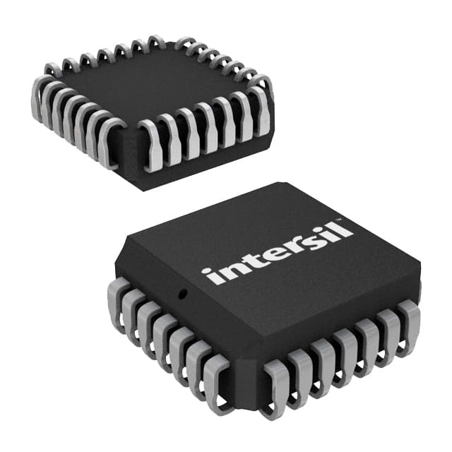
- Part No.:
- IS82C54Z96
- Manufacturer:
- Renesas
- Category:
- Programmable Timers and Oscillators
- Package:
- 28-LCC (J-Lead)
- Datasheet:
-
 IS82C54Z96.pdf
- Description:
- IC OSC PROG TIMER 8MHZ 28PLCC
- Quantity:
- Payment:

- Shipping:

Inventory:3,467
Please send an inquiry. Send us your inquiry, and we will respond immediately.
Product details
Overview
IS82C54Z96 from Intersil is a CMOS programmable interval timer IC with three independent 16-bit counters, supporting up to 8MHz clock input, binary or BCD counting, six programmable modes, and TTL-compatible 5V operation. It serves as a system timing peripheral in legacy x86 embedded controllers for real-time clock generation, event counting, and programmable rate generation.
For engineers reviewing the IS82C54Z96 datasheet, IS82C54Z96 pinout, IS82C54Z96 application, or IS82C54Z96 equivalent, this device delivers deterministic timing control in industrial PLCs, military avionics timing modules, and retro-computing platform replacements where NMOS 8254 compatibility and low-power static CMOS operation are required.
Technical Context
The IS82C54Z96 implements three fully independent synchronous down-counters, each with dedicated CLK, GATE, and OUT terminals, and shares a common 8-bit bidirectional data bus (D0–D7), address decoding (A0/A1), and control interface (RD/WR/CS). Its internal architecture includes a Control Word Register, status latch, and per-counter output latches (OLM/OLL) and count registers (CRM/CRL) enabling non-disruptive read-back of live counter values and mode/status.
It supports all six standard 8254 timer modes-including Mode 0 (interrupt on terminal count), Mode 2 (rate generator), and Mode 3 (square wave)-with precise timing defined by AC parameters such as TCLK = 125 ns (8 MHz), TOD ≤ 150 ns, and TGW ≥ 50 ns. The device operates across –40°C to +85°C and requires only a single +5V supply with ICCOP ≤ 10 mA at 8 MHz.
Key Specifications
| Parameter | Value and Actual Design Meaning |
|---|---|
| Clock Input Frequency | Up to 8 MHz - enables precise microsecond-scale timing intervals in 80C86/80C286-based systems. |
| Counter Width | 16-bit - provides 65,536-step resolution for long-duration delays without software intervention. |
| Supply Voltage | +4.5 V to +5.5 V - ensures robust operation under noisy industrial power rails with 0.1 µF decoupling. |
| Operating Temperature | –40°C to +85°C - qualified for extended-temperature industrial and avionics applications. |
| Power Consumption | ICCOP ≤ 10 mA at 8 MHz - reduces thermal load in dense backplane designs versus NMOS predecessors. |
| Output Compatibility | Fully TTL-compatible - interfaces directly with 74LS/74ALS logic and microprocessor buses without level-shifting. |
| Counting Format | Binary or BCD - supports decimal timekeeping (e.g., seconds/minutes/hours) or binary event counting. |
Pinout & Package
IS82C54Z96 is supplied in a 24-lead PDIP package (Pb-free, RoHS-compliant), with through-hole mounting and wave-solder compatible termination. Pin 12 and Pin 24 are GND and VCC respectively; all I/O pins meet TTL voltage thresholds and drive specifications.
| Pin/Terminal | Circuit Role | Design Meaning |
|---|---|---|
| D0–D7 | Data Bus Interface | Bi-directional 8-bit data path for control word writes, count loading, and status/count read-back. |
| CLK 0–2 | Counter Clock Inputs | Asynchronous rising-edge-triggered inputs; each drives its respective 16-bit down-counter independently. |
| GATE 0–2 | Counter Enable Inputs | High-level enable: gating controls counting start/stop without resetting the counter value. |
| OUT 0–2 | Counter Output Signals | Active-high, open-drain capable outputs reflecting current mode state (e.g., toggle, one-shot, square wave). |
| A0, A1 | Address Select | Decode bus address to select Counter 0, 1, 2, or Control Word Register (A1=A0=1). |
| CS, RD, WR | Chip Control | Standard 8086-style memory-mapped I/O control: CS enables access; RD/WR initiate read/write cycles. |
| VCC, GND | Power Supply | Single +5 V supply with dedicated ground; decoupling capacitor required at VCC–GND per datasheet. |
Key Features
| Feature | Design Value |
|---|---|
| Status Read-Back Command | Enables simultaneous capture of counter output state, null-count flag, and programmed mode-critical for debugging real-time interrupt latency. |
| Counter Latch Function | Latches live count value without halting timing operation, allowing safe "on-the-fly" reads in multi-tasking RTOS environments. |
| Six Programmable Modes | Supports event counting (Mode 0), square-wave generation (Mode 3), and programmable one-shot (Mode 1) within a single chip-reducing board component count. |
| Static CMOS Design | Delivers ICCSB ≤ 10 µA standby current-enabling battery-backed timing in fail-safe monitoring systems. |
| NMOS 8254 Compatibility | Pin- and function-compatible drop-in replacement for legacy 8254 designs, preserving existing PCB layouts and firmware. |
Applications
| Industrial PLC Timing Module | Military Avionics Synchronization |
|---|---|
Use Scenario: Precise 10 ms task scheduling and watchdog timeout generation in ruggedized programmable logic controllers. IC Role / Device Role / Timing Role: System-level interval timer providing deterministic interrupt triggers synchronized to external encoder pulses. Use Value: Eliminates software timing loops, reducing CPU overhead by >95% while guaranteeing sub-millisecond jitter in cyclic executive schedulers. |
Use Scenario: Clock distribution and pulse-width modulation for flight control surface actuation sequencing in airborne computers. IC Role / Device Role / Timing Role: Dual-counter configuration generating synchronized PWM signals with adjustable dead-time insertion via GATE-controlled retriggering. Use Value: Enables hardware-level safety interlocks and deterministic response windows compliant with DO-254 Level A design assurance. |
| Retro-Computing Platform Replacement | Legacy Medical Equipment Maintenance |
Use Scenario: Drop-in upgrade of obsolete NMOS 8254 timers in vintage IBM PC/AT-compatible industrial PCs. IC Role / Device Role / Timing Role: Direct pin-compatible timing peripheral restoring real-time clock, speaker tone, and DMA refresh functions. Use Value: Extends service life of mission-critical legacy systems without firmware modification or PCB redesign. |
Use Scenario: Replacing failed 8254 timers in FDA-cleared patient monitor timing subsystems requiring long-term component availability. IC Role / Device Role / Timing Role: Certified-replacement interval timer ensuring continuity of ECG sampling clock and alarm interval generation. Use Value: Meets IEC 62304 software lifecycle requirements by providing documented RoHS-compliant, temperature-qualified silicon with full traceability. |
Equivalent & Alternatives
The following parts are listed as comparable options for similar programmable timer applications.
| Alternative Part | Technical Difference | Application Difference | Selection Advice |
|---|---|---|---|
| IS82C54-10Z96 | 10 MHz max clock frequency; identical pinout, package, and instruction set. | Required for systems needing >8 MHz timing resolution (e.g., high-speed data acquisition triggers). | Select when higher base clock tolerance is needed; otherwise IS82C54Z96 suffices for standard 80C86 timing. |
| DS82C54Z96 | Same specs and pinout; manufactured by Maxim Integrated (acquired Intersil's timing portfolio). | No functional difference; used in post-acquisition BOM revisions where Maxim part numbering applies. | Preferred for new designs sourcing from Maxim's authorized channels; identical qualification and reliability data. |
Compared with IS82C54-10Z96 and DS82C54Z96, the IS82C54Z96 offers optimal cost-performance balance for 8 MHz-class embedded timing, retains full backward compatibility with legacy 8254 firmware, and provides guaranteed long-term supply under Intersil's extended product support program.
Availability
IS82C54Z96 is available at Aetrix Electronics and suitable for industrial PLC timing modules, military avionics synchronization circuits, retro-computing platform replacements, and legacy medical equipment maintenance requiring stable component supply over extended production lifecycles.
Supply support for IS82C54Z96 includes scheduled delivery planning, volume procurement assistance, BOM continuity management, traceable sourcing, and lifecycle availability coordination for OEM customers, industrial embedded developers, connected-device designers, and electronics production programs.
Manufacturer
Intersil Corporation was a U.S.-based semiconductor company specializing in precision analog, power management, and timing solutions before its acquisition by Renesas Electronics in 2017.
The IS82C54Z96 belongs to Intersil's CMOS programmable timer family, designed specifically to replace power-hungry NMOS 8254s in embedded control systems while maintaining full software and hardware compatibility.
FAQ
What is the maximum clock frequency supported by the IS82C54Z96?
The IS82C54Z96 supports a maximum clock input frequency of 8 MHz, as confirmed by AC Electrical Specifications on page 4 of FN2970 Rev 6.00. This corresponds to a minimum clock period (TCLK) of 125 ns. Exceeding this limit may result in undefined counter behavior or failure to meet timing guarantees for output delay (TOD ≤ 150 ns) and gate setup (TGS ≥ 50 ns).
Does the IS82C54Z96 support BCD counting mode?
Yes, the IS82C54Z96 supports both binary and BCD counting modes. The BCD bit (D0) in the Control Word determines format: when set to '1', the counter operates as a 4-decade BCD counter (0000–9999); when '0', it functions as a 16-bit binary counter (0000–65535). This capability is explicitly listed in the Features section and validated in the Control Word Format table on page 8.
Is the IS82C54Z96 pin-compatible with the original NMOS 8254?
Yes, the IS82C54Z96 is fully pin-compatible and functionally equivalent to the NMOS 8254. The datasheet states "Compatible with NMOS 8254" and confirms identical pin assignments, signal definitions, and programming model. This allows direct replacement in existing designs without PCB or firmware changes, provided the +5V supply and temperature range align.
What is the operating temperature range for the IS82C54Z96?
The IS82C54Z96 is rated for operation from –40°C to +85°C, corresponding to the IX82C54 grade per the Ordering Information table on page 2. This extended temperature range qualifies it for industrial control cabinets, avionics bays, and outdoor deployed equipment where ambient conditions exceed commercial-grade limits.
How does the Read-Back command work on the IS82C54Z96?
The Read-Back command (Control Word with SC1/SC0 = 11 and D5/D4 = 00) allows software to simultaneously latch count values and status flags (OUTPUT, NULL COUNT, mode bits) for one or more counters. Once latched, subsequent reads return the frozen snapshot until the counter is reprogrammed or another Read-Back is issued-enabling reliable diagnostics without disrupting real-time timing operations.
IS82C54Z96 Specifications
- Product attributes
- Attribute value
- Manufacturer:
- Renesas
- Series:
- -
- Package/Case:
- 28-LCC (J-Lead)
- Packaging:
- Tape & Reel (TR)
- Product Status:
- Active
- Type:
- Programmable Timer
- Count:
- -
- Frequency:
- 8MHz
- Voltage - Supply:
- 4.5V ~ 5.5V
- Current - Supply:
- 10 mA
- Operating Temperature:
- -40°C ~ 85°C
- Supplier Device Package:
- 28-PLCC (11.51x11.51)
- Mounting Type:
- Surface Mount
- Grade:
- -
- Qualification:
- -
IS82C54Z96 FAQ
1.How can I place an order for IS82C54Z96 through Aetrix?
Please submit a Request for Quotation (RFQ) for IS82C54Z96 on Aetrix. Our sales agent will provide a competitive quotation and guide you through the order confirmation once you accept the terms.
2.Are the price and stock information for IS82C54Z96 reliable?
The price and inventory of IS82C54Z96 are updated periodically and may fluctuate due to market conditions. Stock and pricing data are typically refreshed every 24 hours. Quotation validity for IS82C54Z96 is usually 5 days.
3.What payment methods are accepted for IS82C54Z96?
We accept Wire Transfer, PayPal, Credit Card, Western Union, MoneyGram, and Escrow for IS82C54Z96 transactions.
Note: Certain payment methods may incur a processing fee.
4.How is shipping managed for IS82C54Z96?
IS82C54Z96 orders can be shipped via leading logistics carriers, including DHL, UPS, FedEx, TNT, or Registered Mail.
Once your IS82C54Z96 order is processed, you will receive an email with the shipment details and tracking number.
Note: Tracking information may take up to 24 hours to appear. Express delivery typically takes 3–5 business days.
5.How can I obtain technical support or documentation for IS82C54Z96?
For technical support, including IS82C54Z96 datasheets, pinout diagrams, or application guidance, please contact our engineering support team. They can provide detailed documentation and assistance for your IS82C54Z96 requirements.
6.How does Aetrix verify that IS82C54Z96 is sourced from the original manufacturer or authorized distributors?
All IS82C54Z96 products on Aetrix are procured from qualified distributors and authorized channels. Our dedicated quality assurance team conducts strict verification, including traceability checks and, if necessary, third-party testing. This ensures that IS82C54Z96 meets industry standards.
7.What is the process for return or replacement of IS82C54Z96?
All IS82C54Z96 units undergo pre-shipment inspection (PSI). If there is an issue with IS82C54Z96, returns or replacements are accepted under the following conditions:
1.Quantity discrepancies, incorrect items, or visible external defects (such as breakage or corrosion), acknowledged by Aetrix.
2.The issue is reported within 90 days of delivery.
3.The IS82C54Z96 part is unused and in its original packaging.
Return procedure for IS82C54Z96:
1.Submit a request within 90 days.
2.Obtain a Return Material Authorization (RMA) from Aetrix.
IS82C54Z96 Tags

-
NE555DR
Texas Instruments
-
SA555DR
Texas Instruments
-
NA555DR
Texas Instruments
-
SE555DR
Texas Instruments

-
NE555P
Texas Instruments

-
CD4541BM96
Texas Instruments

-
CD4541BE
Texas Instruments
-
TLC555QDR
Texas Instruments
-
TLC555IDR
Texas Instruments
-
TLC555QDRQ1
Texas Instruments

-
TPL5010DDCR
Texas Instruments
-
TLC555CP
Texas Instruments
Tech Hub

TTL and CMOS logic families differ in thresholds, loading, output drive, power and timing. This engineering guide compares 74HC and 74HCT, calculates noise margins and checks 3.3 V/5 V compatibility.

A practical engineering guide to 3.3V and 5V logic compatibility, input thresholds, resistor dividers, translator ICs, MOSFET level shifting, I2C pull-ups, timing limits and power-sequencing risks.

The 74HC595 uses push-pull logic outputs, while the TPIC6B595 uses 50 V open-drain DMOS sinks for higher-power loads. This guide compares timing, current limits, 3.3 V interfacing, load wiring, thermal…

The 74HC595 converts serial data into eight stable parallel outputs. This guide covers pin functions, shift and storage timing, OE and MR behavior, drive-current limits, cascading, voltage compatibilit…

A technical comparison of level-sensitive latches and edge-triggered flip-flops, covering timing windows, setup and hold limits, master–slave operation, time borrowing, race-through, HDL inference and…

A D latch stores one bit while Enable controls when data can pass. This reference covers gate-level operation, truth tables, transparency, setup and hold timing, LE versus OE, common ICs and practical …

An SR latch stores one bit through cross-coupled feedback. This engineering reference covers NOR and NAND implementations, truth tables, forbidden-state recovery, gated operation, switch debouncing, fa…

Latch circuits retain one bit through feedback. This technical reference covers SR and D latches, truth tables, transparency, timing limits, latch-versus-flip-flop behavior, applications and common log…

An engineering guide to LED driver operation, constant-current and constant-voltage outputs, linear and switching topologies, dimming, IC selection, calculations, replacement compatibility, and fault c…

Operational amplifier guide covering op amp basics, feedback, ideal vs real op amps, common configurations, buffer circuits, offset, bias current, gain-bandwidth, slew rate, rail-to-rail limits and sel…


