
 My Inquiry
 My Account


Renesas ISL55143IRZ
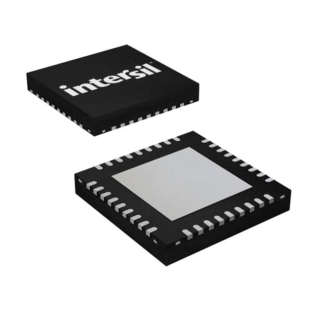
- Part No.:
- ISL55143IRZ
- Manufacturer:
- Renesas
- Category:
- Comparators
- Package:
- 36-WFQFN Exposed Pad
- Datasheet:
-
 ISL55143IRZ.pdf
- Description:
- IC COMPARATOR 4 WINDW 36TQFN
- Quantity:
- Payment:

- Shipping:

Inventory:529
Please send an inquiry. Send us your inquiry, and we will respond immediately.
Product details
Overview
ISL55143IRZ from Intersil is a quad-channel, high-speed 18V CMOS window comparator with dual independent thresholds (CVA/CVB) per channel, 9.5ns typical propagation delay, 65MHz operating frequency, and three-state digital output encoding (QA/QB). It operates across ±3V to ±9V split supplies or 10–18V single supply, supporting burn-in ATE and fast power supervision in flash memory test systems.
For engineers reviewing the ISL55143IRZ datasheet, ISL55143IRZ pinout, ISL55143IRZ application, or ISL55143IRZ equivalent, this device delivers precise 3-level signal qualification (Valid Low / Invalid / Valid High) with user-defined VOH/VOL output rails, wide common-mode input range (VEE to VCC−5V), and power-down capability (<10µA).
Technical Context
The ISL55143IRZ implements four independent dual-threshold comparators, each accepting a shared VINPX input and comparing it against programmable CVAx (high threshold) and CVBx (low threshold) analog references. Output logic states QAx/QBx encode input position relative to both thresholds per Table 1, enabling unambiguous three-state window detection without external logic.
VOH and VOL pins are unbuffered analog supplies that directly set all comparator output high/low voltage levels-supporting interface compatibility with TTL, LVCMOS, ECL, LVDS, and CML logic families. The PD pin enables full device power-down with 10µs exit time, reducing quiescent current from ~33mA (4-channel active at 12V/−3V) to <10µA.
Key Specifications
| Parameter | Value and Actual Design Meaning |
|---|---|
| Propagation Delay | 9.5ns typical at ±50mV overdrive - enables synchronization in 65MHz digital test clock domains. |
| Supply Range | VCC−VEE = 10V to 18V - supports wide-voltage applications including flash memory burn-in and industrial power supervision. |
| Input Common-Mode Range | VEE to VCC−5V - accepts inputs down to negative rail, critical for mixed-signal test fixtures with ground-referenced signals. |
| Output Configuration | Two-bit per-channel QA/QB encoding - provides native three-state qualification (00/01/11) without external decoding logic. |
| Power-Down Current | <10µA - allows low-power idle states in automated test equipment between test sequences. |
| Operating Frequency | 65MHz maximum - matches high-speed digital pattern rates in ATE systems without timing violation. |
| Input Offset Voltage | ±50mV max - ensures accurate threshold discrimination for tight VIH/VIL margin testing. |
Pinout & Package
ISL55143IRZ uses a 36-lead Thin Quad Flat No-Lead (TQFN) package (6mm × 6mm, 0.55mm pitch) with exposed thermal pad electrically connected to VEE. Pin 1 is located in top-left corner of top view, marked by index area.
| Pin/Terminal | Circuit Role | Design Meaning |
|---|---|---|
| CVAX, CVBX (X=0–3) | Independent analog reference inputs per channel | Set high (CVA) and low (CVB) thresholds for three-state window comparison; no internal buffering. |
| VINPX (X=0–3) | Window comparator input | Single analog input per channel evaluated against both CVAx and CVBx thresholds simultaneously. |
| QAX, QBX (X=0–3) | Digital output bits per channel | Encode input state as 00 (below CVB), 01 (between CVB/CVA), or 11 (above CVA); outputs connect directly to VOH/VOL rails. |
| VOH, VOL | User-defined output logic rails | Unbuffered analog supplies setting all QA/QB high/low voltage levels; must satisfy VOH > VOL and remain within (VEE−0.5V) to (VCC+0.5V). |
| VCC, VEE | Positive/negative supply inputs | Support split-rail (e.g., +12V/−3V) or single-supply (e.g., 15V/GND) operation; VEE connects to exposed thermal pad. |
| PD | Power-down control input | Active-low logic input; tie to VEE to enable normal operation, tie to VCC to enter ultra-low-power mode (<10µA). |
| NC | No internal connection | Unused pins (e.g., pins 1, 2, 3, 4, 5, 12, 13, 14, 15, 16, 17, 18, 19, 20, 21, 22, 23, 24, 25, 26, 27, 28, 29, 30, 31, 32, 33, 34, 35) - must be left floating or grounded per layout guidelines. |
Key Features
| Feature | Design Value |
|---|---|
| Dual-threshold per channel | Enables native three-state signal qualification (Valid Low / Invalid / Valid High) without external logic or ADC. |
| User-defined VOH/VOL rails | Allows direct interfacing with diverse logic families (TTL, LVCMOS, ECL, LVDS, CML) using system-specific supply voltages. |
| Wide 18V I/O range | Supports high-voltage test environments (e.g., flash memory VPP programming) without level-shifting circuitry. |
| Power-down mode | Reduces total supply current from ~33mA to <10µA, extending uptime in battery-backed or thermally constrained ATE systems. |
| Negative-rail common-mode support | Accepts inputs down to VEE, enabling ground-referenced signal monitoring in mixed-voltage test fixtures. |
Applications
| Burn-in ATE Testing | Flash Memory Power Supervision |
|---|---|
Use Scenario: Verifying VIH/VIL margins of flash memory devices during high-temperature burn-in cycles using programmable voltage thresholds. IC Role / Device Role / Timing Role: Quad-channel window comparator performing real-time three-state qualification of device I/O lines against dynamically adjusted CVA/CVB references. Use Value: Eliminates need for external DACs and logic decoding, reducing test head component count and improving timing accuracy at 65MHz. | Use Scenario: Monitoring multiple power rails (VCCIO, VPP, VNEG) in NAND/NOR flash controllers for out-of-spec condition detection. IC Role / Device Role / Timing Role: High-speed comparator detecting overvoltage/undervoltage events with sub-10ns response, triggering system reset or fault logging. Use Value: Wide 18V supply range and rail-to-rail input capability allow direct sensing of ±3V to +15V rails without attenuators or op-amp buffers. |
| Low-Cost Automated Test Equipment | High-Speed Instrumentation Signal Conditioning |
Use Scenario: Replacing discrete comparator + logic IC combinations in entry-level ATE platforms requiring multi-channel voltage window checking. IC Role / Device Role / Timing Role: Integrated quad window comparator providing four independent QA/QB outputs with shared VOH/VOL configuration. Use Value: Reduces PCB area by 60% versus discrete solutions and eliminates inter-stage propagation delay skew between channels. | Use Scenario: Converting analog sensor outputs (e.g., current sense, temperature) into three-state digital flags for FPGA-based data acquisition systems. IC Role / Device Role / Timing Role: Precision window detector converting continuous analog waveforms into state-encoded digital streams at up to 65MHz. Use Value: 9.5ns propagation delay and 2ns rise/fall times preserve timing integrity in high-bandwidth measurement loops. |
Equivalent & Alternatives
The following parts are listed as comparable options for similar window comparator applications.
| Alternative Part | Technical Difference | Application Difference | Selection Advice |
|---|---|---|---|
| MAX961 | Single-channel, 4.5ns propagation delay, 2.7–5.5V supply only, no power-down pin | Limited to low-voltage, single-channel use; lacks quad integration and 18V range | Select when ultra-fast single-channel response is required in 3.3V systems without power management needs. |
| LMH7322 | Dual-channel, 2.3ns delay, 2.7–12V supply, no user-defined VOH/VOL, fixed CMOS outputs | Higher speed but narrower voltage range and inflexible output drive; no three-state encoding | Choose for RF/IF signal detection where nanosecond timing dominates over voltage flexibility and multi-state logic. |
Compared with MAX961 and LMH7322, the ISL55143IRZ uniquely combines quad-channel density, 18V operation, user-configurable output rails, and power-down capability-making it the only solution suitable for cost-sensitive, high-voltage ATE and flash power supervision where three-state qualification and thermal efficiency are jointly critical.
Availability
ISL55143IRZ is available at Aetrix Electronics and suitable for burn-in ATE, flash memory power supervision, and low-cost automated test equipment requiring stable component supply, long-term lifecycle support, and RoHS-compliant packaging.
Supply support for ISL55143IRZ includes scheduled delivery planning, volume procurement assistance, BOM continuity management, traceable sourcing, and lifecycle availability coordination for OEM customers, industrial embedded developers, connected-device designers, and electronics production programs.
Manufacturer
Intersil Corporation is a leading provider of precision analog and power management solutions, acquired by Renesas Electronics in 2017. Its products target industrial, infrastructure, and high-end consumer markets.
The ISL55143IRZ belongs to Intersil's high-speed comparator product line, designed specifically for digital test systems requiring wide-voltage window detection, minimal propagation delay, and flexible logic interfacing in compact QFN packages.
FAQ
What is the function of the VOH and VOL pins on the ISL55143IRZ?
The VOH and VOL pins on the ISL55143IRZ are unbuffered analog supply inputs that directly define the high and low voltage levels for all QA/QB outputs. VOH sets the "1" output voltage (e.g., 5V for TTL), VOL sets the "0" output voltage (e.g., 0V), and both must remain within (VEE − 0.5V) to (VCC + 0.5V). Unlike standard logic supplies, these pins require sufficient current sourcing/sinking capability to drive the connected load, as they are not buffered internally. This design enables seamless interface with multiple logic families without level shifters.
How does the ISL55143IRZ implement three-state window comparison?
The ISL55143IRZ implements three-state window comparison per channel using two independent comparators: one driven by CVAx (high threshold) and one by CVBx (low threshold), both evaluating the same VINPx input. Their outputs QA and QB combine to produce three distinct logic states: 00 (input below CVB), 01 (input between CVB and CVA), and 11 (input above CVA). This native encoding eliminates the need for external logic gates or microcontroller polling, delivering deterministic, low-latency state qualification essential for high-speed ATE applications.
What is the recommended power supply sequencing for the ISL55143IRZ?
The ISL55143IRZ requires strict power supply sequencing to prevent EOS damage: apply VEE first, then VOL, followed by VCC, and finally the CVA/CVB reference supplies. The VINPx input must not exceed VEE or VCC during power-up; if transient overvoltage is possible, series current-limiting resistors should be added. This sequence ensures the internal ESD protection diodes remain reverse-biased during ramp-up, preserving reliability in production test environments where supply sequencing may vary across fixture designs.
Can the ISL55143IRZ operate from a single supply, and what are the constraints?
Yes, the ISL55143IRZ can operate from a single supply by tying VEE to ground and applying VCC between 10V and 18V. However, the common-mode input range becomes 0V to (VCC − 5V), limiting the maximum detectable input voltage. Additionally, VOH and VOL must be selected within (0V − 0.5V) to (VCC + 0.5V), and the exposed thermal pad (connected to VEE) must be grounded. Single-supply operation is valid for applications like 12V power supervision but sacrifices the negative-rail input capability available in split-supply configurations.
What is the thermal pad connection requirement for the ISL55143IRZ TQFN package?
The exposed thermal pad on the ISL55143IRZ's 36-lead TQFN package is electrically connected to the VEE supply pin and must be soldered to a PCB copper pour tied to VEE. If VEE is grounded, the pad connects directly to the system ground plane; if VEE is negative (e.g., −3V), the pad must be isolated from other power planes and routed exclusively to the VEE net. This connection is mandatory for thermal performance (θJC = 0.75°C/W) and electrical integrity-floating or misconnected pads cause excessive junction temperature rise and potential device failure under sustained 65MHz operation.
ISL55143IRZ Specifications
- Product attributes
- Attribute value
- Manufacturer:
- Renesas
- Package/Case:
- 36-WFQFN Exposed Pad
- Series:
- -
- Packaging:
- Tube
- Product Status:
- Obsolete
- Type:
- Window
- Number of Elements:
- 4
- Output Type:
- -
- Voltage - Supply, Single/Dual (±):
- 10V ~ 18V
- :
- 50mV @ -3V, 12V
- Voltage - Input Offset (Max):
- 0.025µA @ -3V, 12V
- Current - Input Bias (Max):
- -
- Current - Output (Typ):
- 12.5mA
- Current - Quiescent (Max):
- -
- CMRR, PSRR (Typ):
- 15ns
- Propagation Delay (Max):
- -
- Hysteresis:
- -40°C ~ 85°C
- Operating Temperature:
- -
- Grade:
- -
- Qualification:
- Surface Mount
- :
- 36-TQFN (6x6)
ISL55143IRZ FAQ
1.How can I place an order for ISL55143IRZ through Aetrix?
Please submit a Request for Quotation (RFQ) for ISL55143IRZ on Aetrix. Our sales agent will provide a competitive quotation and guide you through the order confirmation once you accept the terms.
2.Are the price and stock information for ISL55143IRZ reliable?
The price and inventory of ISL55143IRZ are updated periodically and may fluctuate due to market conditions. Stock and pricing data are typically refreshed every 24 hours. Quotation validity for ISL55143IRZ is usually 5 days.
3.What payment methods are accepted for ISL55143IRZ?
We accept Wire Transfer, PayPal, Credit Card, Western Union, MoneyGram, and Escrow for ISL55143IRZ transactions.
Note: Certain payment methods may incur a processing fee.
4.How is shipping managed for ISL55143IRZ?
ISL55143IRZ orders can be shipped via leading logistics carriers, including DHL, UPS, FedEx, TNT, or Registered Mail.
Once your ISL55143IRZ order is processed, you will receive an email with the shipment details and tracking number.
Note: Tracking information may take up to 24 hours to appear. Express delivery typically takes 3–5 business days.
5.How can I obtain technical support or documentation for ISL55143IRZ?
For technical support, including ISL55143IRZ datasheets, pinout diagrams, or application guidance, please contact our engineering support team. They can provide detailed documentation and assistance for your ISL55143IRZ requirements.
6.How does Aetrix verify that ISL55143IRZ is sourced from the original manufacturer or authorized distributors?
All ISL55143IRZ products on Aetrix are procured from qualified distributors and authorized channels. Our dedicated quality assurance team conducts strict verification, including traceability checks and, if necessary, third-party testing. This ensures that ISL55143IRZ meets industry standards.
7.What is the process for return or replacement of ISL55143IRZ?
All ISL55143IRZ units undergo pre-shipment inspection (PSI). If there is an issue with ISL55143IRZ, returns or replacements are accepted under the following conditions:
1.Quantity discrepancies, incorrect items, or visible external defects (such as breakage or corrosion), acknowledged by Aetrix.
2.The issue is reported within 90 days of delivery.
3.The ISL55143IRZ part is unused and in its original packaging.
Return procedure for ISL55143IRZ:
1.Submit a request within 90 days.
2.Obtain a Return Material Authorization (RMA) from Aetrix.
ISL55143IRZ Tags

-
LM2903DR
Texas Instruments

-
LM339DR
Texas Instruments

-
LM339PWR
Texas Instruments

-
LM393DT
STMicroelectronics
-
LM2901PWR
Texas Instruments
-
LM2903DT
STMicroelectronics
-
LM393DR
Texas Instruments
-
LM239DR
Texas Instruments
-
LM339APWR
Texas Instruments

-
LM2903P
Texas Instruments
-
LM393ADR
Texas Instruments
-
NCX2200GMAZ
NXP Semiconductors
Tech Hub

TTL and CMOS logic families differ in thresholds, loading, output drive, power and timing. This engineering guide compares 74HC and 74HCT, calculates noise margins and checks 3.3 V/5 V compatibility.

A practical engineering guide to 3.3V and 5V logic compatibility, input thresholds, resistor dividers, translator ICs, MOSFET level shifting, I2C pull-ups, timing limits and power-sequencing risks.

The 74HC595 uses push-pull logic outputs, while the TPIC6B595 uses 50 V open-drain DMOS sinks for higher-power loads. This guide compares timing, current limits, 3.3 V interfacing, load wiring, thermal…

The 74HC595 converts serial data into eight stable parallel outputs. This guide covers pin functions, shift and storage timing, OE and MR behavior, drive-current limits, cascading, voltage compatibilit…

A technical comparison of level-sensitive latches and edge-triggered flip-flops, covering timing windows, setup and hold limits, master–slave operation, time borrowing, race-through, HDL inference and…

A D latch stores one bit while Enable controls when data can pass. This reference covers gate-level operation, truth tables, transparency, setup and hold timing, LE versus OE, common ICs and practical …

An SR latch stores one bit through cross-coupled feedback. This engineering reference covers NOR and NAND implementations, truth tables, forbidden-state recovery, gated operation, switch debouncing, fa…

Latch circuits retain one bit through feedback. This technical reference covers SR and D latches, truth tables, transparency, timing limits, latch-versus-flip-flop behavior, applications and common log…

An engineering guide to LED driver operation, constant-current and constant-voltage outputs, linear and switching topologies, dimming, IC selection, calculations, replacement compatibility, and fault c…

Operational amplifier guide covering op amp basics, feedback, ideal vs real op amps, common configurations, buffer circuits, offset, bias current, gain-bandwidth, slew rate, rail-to-rail limits and sel…


