
 My Inquiry
 My Account


Renesas ISL6504ACR
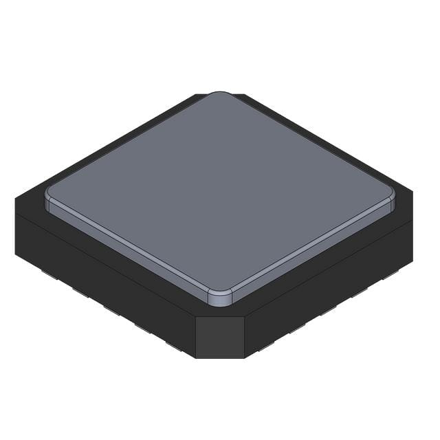
- Part No.:
- ISL6504ACR
- Manufacturer:
- Renesas
- Category:
- Power Supply Controllers, Monitors
- Package:
- 20-VQFN Exposed Pad
- Datasheet:
-
 ISL6504ACR.pdf
- Description:
- IC MULTIPLE POWER CTRLR 20-QFN
- Quantity:
- Payment:

- Shipping:

Inventory:4,758
Please send an inquiry. Send us your inquiry, and we will respond immediately.
Product details
Overview
ISL6504ACR from Intersil is a multiple linear power controller with ACPI control interface, integrating three linear regulators and dual switching controllers for 3.3VDUAL/3.3VSB, 5VDUAL, 1.2VVID, and 1.5VSB outputs in a single IC. It operates across 0°C to 70°C, delivers ±2.0% output voltage regulation, supports S0–S5 ACPI states, and uses external NPN/N-MOS/PMOS pass devices for flexible power delivery in ATX-compliant motherboard designs.
For engineers reviewing the ISL6504ACR datasheet, ISL6504ACR pinout, ISL6504ACR application, or ISL6504ACR equivalent, key selection considerations include its QFN-20 package footprint, S3/S5 digital sleep-state control logic, 5VDUAL behavior in S4/S5 (remains active), undervoltage monitoring across all four outputs, and thermal shutdown at 155°C - critical for reliable ACPI power sequencing in embedded and desktop computing platforms.
Technical Context
The ISL6504ACR implements a state-machine-driven ACPI controller with dedicated error amplifiers for each regulated output (1.5VSB, 1.2VVID, 3.3VDUAL/3.3VSB) and dual-switch control logic for 5VDUAL. Its internal 10 μA soft-start current source charges an external capacitor to coordinate ramp-up timing across outputs during POR and state transitions.
It features deglitched S3/S5 inputs (2 μs filter), 200 μs S3-to-sleep delay, and independent UV detection per output with 10–30 ms fault response latency. The FAULT pin reports undervoltage, overtemperature (>140°C flag, >155°C shutdown), or illegal state transitions via open-collector pull-up to 5VSB.
Key Specifications
| Parameter | Value and Actual Design Meaning |
|---|---|
| Operating Temp Range | 0°C to 70°C ambient - validated for commercial motherboard environments without derating. |
| Output Voltage Accuracy | ±2.0% over temperature - ensures stable VID, standby, and dual-rail supplies under thermal stress. |
| Soft-Start Current | 10 μA typical - enables precise external capacitor-based timing control for sequential output ramp-up. |
| 5VDUAL Behavior in S4/S5 | Remains active - distinguishes ISL6504ACR from ISL6504CR; required for USB wake-on-LAN or resume-from-disk functionality. |
| Thermal Shutdown Threshold | 155°C junction - provides fail-safe protection while allowing operation up to 125°C continuous junction temperature. |
| FAULT Pin Output Impedance | 100 Ω when high - ensures robust low-impedance reporting to system logic under fault conditions. |
| VID_CT Charging Current | 10 μA - sets programmable delay for VID_PG assertion, enabling synchronization with processor power-good timing. |
Pinout & Package
ISL6504ACR is housed in a 20-pin 6×6 mm QFN package with exposed thermal pad connected to GND. The bottom pad improves thermal performance (θJC = 4.0°C/W) and may be left unconnected or tied to GND plane.
| Pin/Terminal | Circuit Role | Design Meaning |
|---|---|---|
| 1 (1V5SB) | 1.5VSB regulator output | Internal LDO output sourcing up to 85 mA from 3V3DL; active whenever 5VSB is present. |
| 2 (3V3DLSB) | NPN base drive for 3.3VDUAL/3.3VSB sleep regulation | Drives external NPN transistor to regulate 3.3V during S3/S4/S5 states using 5VSB as input. |
| 3 (3V3DL) | 3.3VDUAL/3.3VSB output node | Regulated output node monitored for UV; supplies current to 1V5SB and external loads (PCI, LAN). |
| 4 (1V2VID) | 1.2V VID circuitry supply | Internal LDO output (40 mA max) active only in S0/S1/S2; powers CPU voltage identification logic. |
| 5 (3V3) | ATX 3.3V input reference | Connects to main ATX 3.3V rail; supplies current to 1V2VID and serves as UV monitor point. |
| 6 (S3) | Suspend-to-RAM control input | Digital input with 50 kΩ pull-up to 5VSB; initiates S3 entry after 200 μs debounce and state validation. |
| 7 (S5) | Suspend-to-disk/soft-off control input | Digital input with 50 kΩ pull-up to 5VSB; combined with S3 determines ACPI sleep state (S4/S5). |
| 8 (GND) | Signal ground reference | Common return for all analog and digital functions; must be low-impedance connection to PCB ground plane. |
| 9 (FAULT) | Open-collector fault indicator | Pulled to 5VSB on any UV event, overtemperature (>140°C), or illegal state transition; requires 1 kΩ pull-down. |
| 10 (DLA) | N-MOS gate drive for 3.3V/5V switching | Open-collector output driving external N-MOSFET gates (via 1 kΩ to 12V) to connect ATX rails in active state. |
| 11 (5VDLSB) | P-MOS/PNP gate drive for 5VDUAL sleep path | Drives external PMOS or PNP to connect 5VSB to 5VDUAL in S3 (ISL6504ACR) and S3+S4/S5 (ISL6504ACR). |
| 12 (5VDL) | 5VDUAL output node | Switched output node monitored for UV; connects to ATX 5V in active state, 5VSB in S3/S4/S5. |
| 13 (SS) | Soft-start and shutdown control | External capacitor node for ramp timing; pulled low (<0.8V) forces full shutdown and FAULT reset. |
| 14 (VID_PG) | 1.2VVID power-good indicator | Open-collector output asserting when 1V2VID exceeds 1.02 V; requires 10 kΩ pull-up to 1V2VID. |
| 15 (VID_CT) | VID_PG delay timing capacitor | Connects to GND; 10 μA internal current source sets delay before VID_PG assertion (e.g., 10 nF ≈ 0.125 ms). |
| 16 (5VSB) | Main bias supply input | Accepts +5V ±5% from ATX 5VSB; powers entire IC and serves as POR reference (4.5V threshold). |
| 17–20 (NC) | No-connect terminals | Unused pins in QFN-20 package; must remain unconnected per datasheet guidance. |
Key Features
| Feature | Design Value |
|---|---|
| Four ACPI-controlled outputs | Simultaneously manages 5VDUAL (USB/keyboard), 3.3VDUAL/3.3VSB (PCI/LAN), 1.2VVID (CPU VID), and 1.5VSB (ICH4 resume well) with coordinated sequencing. |
| State-aware regulation | 3.3VDUAL/3.3VSB uses NPN in sleep states and N-MOS in active states; 5VDUAL remains on in S4/S5 - enabling wake-from-disk capability. |
| Centralized fault reporting | Single FAULT pin aggregates undervoltage events across all four outputs, input rails (3V3, 5VSB), and die temperature - simplifying system-level fault handling. |
| Programmable soft-start | External CSS capacitor sets ramp time for 3.3VDUAL/3.3VSB and 1.5VSB; second-stage ramp enables controlled 1.2VVID startup after main ATX rails stabilize. |
| Robust input conditioning | S3/S5 inputs feature 2 μs deglitching and state-transition blocking logic to prevent illegal S3↔S4/S5 jumps - ensuring deterministic ACPI compliance. |
Applications
| Desktop Motherboard Power Management | Embedded Industrial Control Board |
|---|---|
Use Scenario: Regulating auxiliary power rails on ATX-compliant desktop motherboards supporting ACPI S0–S5 states. IC Role / Device Role / Timing Role: Central ACPI power controller coordinating 3.3VDUAL, 5VDUAL, 1.2VVID, and 1.5VSB sequencing with S3/S5 state decoding and fault aggregation. Use Value: Eliminates discrete supervisor ICs and reduces external component count by integrating four regulated outputs and centralized monitoring in one QFN-20 device. | Use Scenario: Providing reliable standby and wake-capable power for fanless industrial PCs requiring S3 suspend/resume and S4/S5 hibernation. IC Role / Device Role / Timing Role: Dual-mode linear/switching controller delivering always-on 1.5VSB and 3.3VSB while maintaining 5VDUAL during S4/S5 for network wake signals. Use Value: Enables zero-power-consumption hibernation with guaranteed resume capability via persistent 5VDUAL - critical for remote management in headless systems. |
| Laptop Docking Station Power Hub | Network Attached Storage (NAS) Controller Board |
Use Scenario: Managing shared power domains between laptop and dock peripherals including USB, Ethernet, and PCIe expansion slots. IC Role / Device Role / Timing Role: Linear regulator and switch controller generating 3.3VSB for PCI Express AUX power and 5VDUAL for USB charging ports during both active and sleep states. Use Value: Supports USB wake-on-connect and LAN wake-on-ring through sustained 5VDUAL in S4/S5 - eliminating need for separate always-on power ICs. | Use Scenario: Supplying chipset standby, SATA PHY, and USB controller power in multi-bay NAS units with scheduled wake/sleep cycles. IC Role / Device Role / Timing Role: ACPI-compliant power sequencer delivering 1.5VSB for ICH4 resume well and 3.3VDUAL for LAN controller, with S4/S5 persistence for scheduled backup triggers. Use Value: Reduces BOM cost and board area by consolidating four precision-regulated rails into one IC with integrated UV/thermal protection and fault signaling. |
Equivalent & Alternatives
The following parts are listed as comparable options for similar multiple-output ACPI power controller applications.
| Alternative Part | Technical Difference | Application Difference | Selection Advice |
|---|---|---|---|
| ISL6504CR | Identical pinout and function except 5VDUAL shuts down in S4/S5 states. | Not suitable where persistent 5VDUAL is required for wake-on-LAN or USB resume. | Select ISL6504CR only if S4/S5 hibernation does not require 5VDUAL continuity. |
| RT8205A | QFN-32, integrates MOSFET drivers but lacks native S4/S5 5VDUAL hold-on; requires external logic for S4/S5 persistence. | Higher integration of gate drivers but no built-in S4/S5 5VDUAL retention - adds complexity for wake-from-disk use cases. | Choose RT8205A only when MOSFET driver integration outweighs need for seamless S4/S5 5VDUAL support. |
Compared with ISL6504CR and RT8205A, the ISL6504ACR uniquely guarantees 5VDUAL continuity across all ACPI sleep states - a hardware-enforced requirement for reliable resume-from-disk and wake-on-LAN in legacy and embedded ATX platforms without firmware or external logic intervention.
Availability
ISL6504ACR is available at Aetrix Electronics and suitable for desktop motherboard design, industrial embedded control, and network-attached storage applications requiring stable component supply and long-term lifecycle support.
Supply support for ISL6504ACR includes scheduled delivery planning, volume procurement assistance, BOM continuity management, traceable sourcing, and lifecycle availability coordination for OEM customers, industrial embedded developers, connected-device designers, and electronics production programs.
Manufacturer
Intersil Corporation (now part of Renesas Electronics) is a U.S.-based semiconductor company specializing in precision analog and power management ICs for computing, industrial, and communications markets.
The ISL6504 product line was designed specifically for ACPI-compliant motherboard power sequencing, integrating multiple linear regulators and switching controllers to replace discrete supervisor and regulator solutions in space-constrained ATX designs.
FAQ
What is the key functional difference between ISL6504ACR and ISL6504CR?
The ISL6504ACR maintains 5VDUAL output during S4/S5 sleep states, whereas the ISL6504CR shuts down 5VDUAL in S4/S5. This distinction is hardware-defined and enables wake-on-LAN and resume-from-disk functionality without external circuitry. All other electrical characteristics, pinout, and package dimensions are identical between ISL6504ACR and ISL6504CR.
Does ISL6504ACR require external pass transistors for all outputs?
Yes - ISL6504ACR requires external pass devices: an NPN transistor for 3.3VDUAL/3.3VSB in sleep states, NMOS transistors driven by DLA for 3.3V/5V connection in active states, and a PMOS or PNP transistor driven by 5VDLSB for 5VDUAL in S3/S4/S5. Only the 1.5VSB and 1.2VVID regulators are fully integrated with internal pass elements.
How does the FAULT pin behave during undervoltage events on ISL6504ACR outputs?
When any monitored output (1.5VSB, 1.2VVID, 3.3VDUAL/3.3VSB, 5VDUAL) or input (3V3, 5VSB) falls below its UV threshold, the FAULT pin is pulled high to 5VSB via an internal ~100 Ω driver. For internally regulated outputs (1.5VSB, 1.2VVID), the faulting regulator shuts off; for externally switched outputs, only the FAULT signal asserts - the external FET remains under system control.
Can ISL6504ACR operate without the SS (soft-start) capacitor?
No - the SS capacitor is mandatory. It sets the timing for coordinated output ramp-up during power-on and state transitions. Omitting it disables soft-start, risks output overshoot, violates UV monitor activation sequence, and may trigger immediate FAULT latching due to uncontrolled voltage rise. A 0.1 μF ceramic capacitor is recommended per datasheet guidelines for ISL6504ACR.
What thermal performance can be expected from ISL6504ACR in its QFN-20 package?
The ISL6504ACR QFN-20 package delivers θJC = 4.0°C/W and θJA = 32°C/W under standard test conditions. With proper PCB layout - including a solid GND plane, thermal vias under the exposed pad, and adequate copper area - it sustains continuous operation up to 125°C junction temperature and triggers unconditional shutdown only at 155°C, ensuring robust thermal safety in dense motherboard layouts.
ISL6504ACR Specifications
- Product attributes
- Attribute value
- Manufacturer:
- Renesas
- Series:
- -
- Package/Case:
- 20-VQFN Exposed Pad
- Packaging:
- Tube
- Product Status:
- Obsolete
- Programmable:
- Not Verified
- Applications:
- Power Supply Controller/Monitor
- Voltage - Input:
- -
- Voltage - Supply:
- 4.75V ~ 5.25V
- Current - Supply:
- 17 mA
- Operating Temperature:
- 0°C ~ 70°C
- Grade:
- -
- Qualification:
- -
- Mounting Type:
- Surface Mount
- Supplier Device Package:
- 20-QFN (6x6)
ISL6504ACR FAQ
1.How can I place an order for ISL6504ACR through Aetrix?
Please submit a Request for Quotation (RFQ) for ISL6504ACR on Aetrix. Our sales agent will provide a competitive quotation and guide you through the order confirmation once you accept the terms.
2.Are the price and stock information for ISL6504ACR reliable?
The price and inventory of ISL6504ACR are updated periodically and may fluctuate due to market conditions. Stock and pricing data are typically refreshed every 24 hours. Quotation validity for ISL6504ACR is usually 5 days.
3.What payment methods are accepted for ISL6504ACR?
We accept Wire Transfer, PayPal, Credit Card, Western Union, MoneyGram, and Escrow for ISL6504ACR transactions.
Note: Certain payment methods may incur a processing fee.
4.How is shipping managed for ISL6504ACR?
ISL6504ACR orders can be shipped via leading logistics carriers, including DHL, UPS, FedEx, TNT, or Registered Mail.
Once your ISL6504ACR order is processed, you will receive an email with the shipment details and tracking number.
Note: Tracking information may take up to 24 hours to appear. Express delivery typically takes 3–5 business days.
5.How can I obtain technical support or documentation for ISL6504ACR?
For technical support, including ISL6504ACR datasheets, pinout diagrams, or application guidance, please contact our engineering support team. They can provide detailed documentation and assistance for your ISL6504ACR requirements.
6.How does Aetrix verify that ISL6504ACR is sourced from the original manufacturer or authorized distributors?
All ISL6504ACR products on Aetrix are procured from qualified distributors and authorized channels. Our dedicated quality assurance team conducts strict verification, including traceability checks and, if necessary, third-party testing. This ensures that ISL6504ACR meets industry standards.
7.What is the process for return or replacement of ISL6504ACR?
All ISL6504ACR units undergo pre-shipment inspection (PSI). If there is an issue with ISL6504ACR, returns or replacements are accepted under the following conditions:
1.Quantity discrepancies, incorrect items, or visible external defects (such as breakage or corrosion), acknowledged by Aetrix.
2.The issue is reported within 90 days of delivery.
3.The ISL6504ACR part is unused and in its original packaging.
Return procedure for ISL6504ACR:
1.Submit a request within 90 days.
2.Obtain a Return Material Authorization (RMA) from Aetrix.
ISL6504ACR Tags

-
UC3845AD8TR
Texas Instruments
-
UC2843AD8TR
Texas Instruments

-
LM3880MFX-1AE/NOPB
Texas Instruments
-
LM3880MFX-1AA/NOPB
Texas Instruments

-
INA234AIYBJR
Texas Instruments

-
INA700AYWFR
Texas Instruments
-
LM3880MF-1AE/NOPB
Texas Instruments
-
LM3880MF-1AA/NOPB
Texas Instruments

-
LM3881MM/NOPB
Texas Instruments
-
UCC2802DTR
Texas Instruments

-
NCP4305DMTTWG
onsemi

-
INA237AIDGSR
Texas Instruments
Tech Hub

TTL and CMOS logic families differ in thresholds, loading, output drive, power and timing. This engineering guide compares 74HC and 74HCT, calculates noise margins and checks 3.3 V/5 V compatibility.

A practical engineering guide to 3.3V and 5V logic compatibility, input thresholds, resistor dividers, translator ICs, MOSFET level shifting, I2C pull-ups, timing limits and power-sequencing risks.

The 74HC595 uses push-pull logic outputs, while the TPIC6B595 uses 50 V open-drain DMOS sinks for higher-power loads. This guide compares timing, current limits, 3.3 V interfacing, load wiring, thermal…

The 74HC595 converts serial data into eight stable parallel outputs. This guide covers pin functions, shift and storage timing, OE and MR behavior, drive-current limits, cascading, voltage compatibilit…

A technical comparison of level-sensitive latches and edge-triggered flip-flops, covering timing windows, setup and hold limits, master–slave operation, time borrowing, race-through, HDL inference and…

A D latch stores one bit while Enable controls when data can pass. This reference covers gate-level operation, truth tables, transparency, setup and hold timing, LE versus OE, common ICs and practical …

An SR latch stores one bit through cross-coupled feedback. This engineering reference covers NOR and NAND implementations, truth tables, forbidden-state recovery, gated operation, switch debouncing, fa…

Latch circuits retain one bit through feedback. This technical reference covers SR and D latches, truth tables, transparency, timing limits, latch-versus-flip-flop behavior, applications and common log…

An engineering guide to LED driver operation, constant-current and constant-voltage outputs, linear and switching topologies, dimming, IC selection, calculations, replacement compatibility, and fault c…

Operational amplifier guide covering op amp basics, feedback, ideal vs real op amps, common configurations, buffer circuits, offset, bias current, gain-bandwidth, slew rate, rail-to-rail limits and sel…


