
 My Inquiry
 My Account


Renesas ISL6504ACR-T
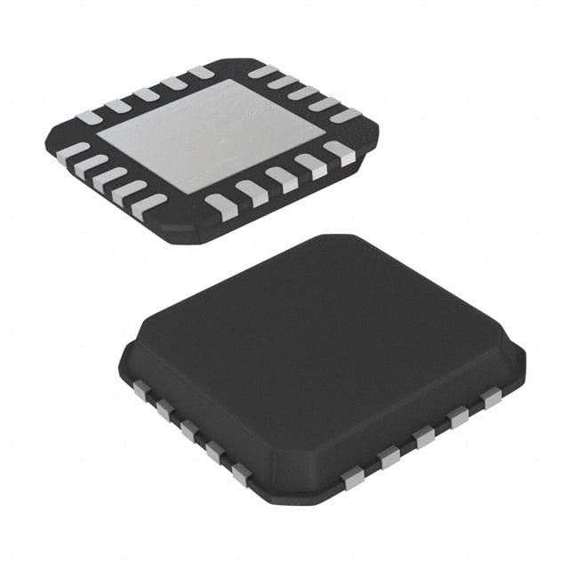
- Part No.:
- ISL6504ACR-T
- Manufacturer:
- Renesas
- Category:
- Power Supply Controllers, Monitors
- Package:
- 20-VQFN Exposed Pad
- Datasheet:
-
 ISL6504ACR-T.pdf
- Description:
- IC MULTIPLE POWER CTRLR 20-QFN
- Quantity:
- Payment:

- Shipping:

Inventory:2,474
Please send an inquiry. Send us your inquiry, and we will respond immediately.
Product details
Overview
ISL6504ACR-T from Intersil is a multiple linear power controller with ACPI control interface, integrating three linear regulators and dual switching controllers for 1.5VSB, 1.2VVID, 3.3VDUAL/3.3VSB, and 5VDUAL outputs in a single 20-pin QFN 6×6 package. It delivers ±2.0% output regulation over temperature, supports S0–S5 ACPI states, and uses external NPN/N-MOS/PMOS pass devices for dynamic voltage routing in motherboard power systems.
For engineers reviewing the ISL6504ACR-T datasheet, ISL6504ACR-T pinout, ISL6504ACR-T application, or ISL6504ACR-T equivalent, key selection considerations include its S4/S5 sleep-state 5VDUAL retention (vs. ISL6504), 0°C to 70°C operating range, QFN thermal resistance (θJA = 32°C/W), fault reporting via open-drain FAULT pin, and VID_PG timing control through VID_CT capacitor.
Technical Context
The ISL6504ACR-T implements ACPI-compliant state transitions using dual digital inputs (S3, S5) with internal 50 kΩ pull-ups to 5VSB and 2 μs noise filtering. Its architecture separates active-state operation (S0/S1/S2) - where 3.3VDUAL connects directly to ATX 3.3V and 5VDUAL to ATX 5V - from sleep states (S3/S4/S5), where 3.3VDUAL is regulated from 5VSB via external NPN and 5VDUAL remains powered from 5VSB via PMOS/PNP.
It integrates four independent regulation paths: an internal 1.5VSB LDO (VOUT1) sourcing from 3V3DL, an internal 1.2VVID LDO (VOUT2) active only in S0/S1/S2 and sourcing from 3V3, a 3.3VDUAL/3.3VSB linear controller (VOUT3) with dual-path topology, and a 5VDUAL switch controller (VOUT4) with undervoltage detection at 4.10 V and hysteresis of 200 mV.
Key Specifications
| Parameter | Value and Actual Design Meaning |
|---|---|
| Operating Temp Range | 0°C to 70°C - validated for commercial motherboard environments without extended industrial derating. |
| Package | 20-pin QFN 6×6 mm - exposes thermal pad tied to GND; θJA = 32°C/W enables compact high-power-density layouts. |
| Output Regulation Accuracy | ±2.0% over temperature - applies to all four outputs (1.5VSB, 1.2VVID, 3.3VDUAL, 5VDUAL), ensuring stable chipset and processor VID supply. |
| 5VDUAL Sleep Behavior | Remains active in S4/S5 - distinguishes ISL6504A from ISL6504; enables USB wake-from-disk and LAN resume functionality. |
| Soft-Start Current | 10 μA - charges external CSS capacitor to control ramp rate of all outputs, preventing 5VSB rail collapse during power-up. |
| FAULT Reporting | Open-drain to 5VSB - asserts low-impedance fault signal on any output UV event or junction temp ≥140°C (typical). |
| VID_PG Delay Control | 10 μA current source into VID_CT capacitor - sets precise power-good assertion timing for CPU VID circuitry (e.g., 10 nF → ~12 ms delay). |
Pinout & Package
ISL6504ACR-T uses a 20-pin QFN 6×6 mm package with exposed thermal pad electrically connected to GND. The bottom pad may be left unconnected or soldered to GND plane; connection to any other potential is prohibited.
| Pin/Terminal | Circuit Role | Design Meaning |
|---|---|---|
| 1 (1V5SB) | 1.5V standby regulator output | Delivers up to 85 mA to ICH4 resume well; sourced from 3V3DL pin; monitored for UV at 1.25 V. |
| 2 (3V3DLSB) | NPN base drive for 3.3VDUAL sleep regulation | Drives external NPN transistor in S3/S4/S5 to regulate 3.3VDUAL from 5VSB; max 8 mA sink capability. |
| 3 (3V3DL) | 3.3VDUAL/3.3VSB output node | Primary regulated output node; supplies south bridge, PCI slots, and 1.5VSB LDO; monitored for UV at 2.75 V. |
| 4 (1V2VID) | 1.2V VID regulator output | Active only in S0/S1/S2; supplies CPU VID circuitry; shut down in all sleep states; 40 mA max output. |
| 5 (3V3) | ATX 3.3V input reference | Connects to ATX 3.3V rail; powers 1.2VVID LDO and serves as UV monitor input (2.75 V threshold). |
| 6 (S3) | ACPI S3 state control input | Digital input with 50 kΩ pull-up to 5VSB; 200 μs delay before S3 entry; deglitched against 2 μs noise. |
| 7 (S5) | ACPI S4/S5 state control input | Digital input with 50 kΩ pull-up to 5VSB; combined with S3 determines full ACPI state machine per Table 1. |
| 8 (GND) | Signal ground reference | Common return for all analog and digital circuits; must connect to PCB ground plane with low-inductance path. |
| 9 (FAULT) | Open-drain fault indicator | Pulled to 5VSB on any UV fault or overtemperature; requires 1 kΩ pull-down to GND for logic-level signaling. |
| 10 (DLA) | N-MOS gate drive for 3.3V/5V switching | Open-collector output; drives gates of external N-MOSFETs in active state via 1 kΩ pull-up to 12V. |
| 11 (5VDLSB) | PMOS/PNP gate drive for 5VDUAL sleep | Drives external PMOS/PNP in S3/S4/S5 to connect 5VSB to 5VDUAL; distinguishes ISL6504A behavior. |
| 12 (5VDL) | 5VDUAL output node | Switched output node; connected to ATX 5V in active state, to 5VSB in S3/S4/S5; monitored for UV at 4.10 V. |
| 13 (SS) | Soft-start and shutdown control | 10 μA current source charges external capacitor; pulled <0.8 V to force global shutdown and reset FAULT. |
| 14 (VID_PG) | 1.2VVID power-good indicator | Open-collector output; asserted after VID_CT capacitor charges past 1.25 V; requires 10 kΩ pull-up to 1.2VVID. |
| 15 (VID_CT) | VID_PG timing capacitor node | Accepts external capacitor to set VID_PG delay; 10 μA internal current source defines timing (e.g., 10 nF → ~12 ms). |
| 16 (5VSB) | Main bias supply input | Connects to ATX 5VSB rail; powers entire IC; monitored for POR at 4.5 V with 0.9 V hysteresis. |
| 17–20 (NC) | No-connect terminals | Not internally bonded; must remain unconnected per datasheet; no routing or stitching required. |
Key Features
| Feature | Design Value |
|---|---|
| Four ACPI-controlled voltage rails | Simultaneously manages 5VDUAL (USB/keyboard), 3.3VDUAL/3.3VSB (PCI/LAN), 1.2VVID (CPU VID), and 1.5VSB (ICH4 resume well) with state-aware routing. |
| S4/S5 5VDUAL retention | Enables wake-on-LAN and USB device resume from disk-off state - unique to ISL6504A variant and critical for modern ACPI compliance. |
| Centralized fault reporting | Single open-drain FAULT pin reports undervoltage on any output or input rail, plus overtemperature events, simplifying system-level monitoring. |
| Programmable VID_PG timing | VID_CT pin accepts external capacitor to precisely delay 1.2VVID power-good assertion, aligning with CPU VID sequencing requirements. |
| Thermally optimized QFN package | 6×6 mm QFN with exposed GND pad achieves θJA = 32°C/W - 55% lower than SOIC - supporting higher ambient and sustained load conditions. |
Applications
| Desktop Motherboard Power Management | ACPI-Compliant Sleep State Sequencing |
|---|---|
Use Scenario: Regulating auxiliary power rails on ATX-compliant desktop motherboards with Intel ICH4 southbridge and Pentium 4-class CPUs. IC Role / Device Role / Timing Role: Central ACPI power controller managing 1.5VSB, 1.2VVID, 3.3VDUAL, and 5VDUAL with state-dependent pass-device switching. Use Value: Eliminates need for discrete linear regulators and logic for S0–S5 transitions; reduces BOM count by 7+ components while guaranteeing ±2.0% regulation. | Use Scenario: Enabling reliable wake-from-disk (S4) and soft-off (S5) states with persistent 5VDUAL for USB and LAN peripherals. IC Role / Device Role / Timing Role: Maintains 5VDUAL rail active during S4/S5 via PMOS-driven 5VSB path - exclusive to ISL6504A - while coordinating soft-start and fault response. Use Value: Supports Windows XP/Vista hibernation standards without external hold-up circuitry; eliminates risk of peripheral disconnect during resume. |
| Processor VID Supply Stabilization | Southbridge & I/O Auxiliary Power |
Use Scenario: Delivering tightly regulated 1.2V to CPU voltage identification circuitry during active states only. IC Role / Device Role / Timing Role: Internal LDO (VOUT2) sourcing from ATX 3.3V rail, active solely in S0/S1/S2, with VID_PG timing controlled by VID_CT capacitor. Use Value: Ensures CPU VID accuracy within ±2.0% across temperature; programmable PG delay prevents premature core enable before VID settling. | Use Scenario: Powering southbridge, PCI slots, and integrated LAN PHY during both active and sleep states. IC Role / Device Role / Timing Role: Dual-path 3.3VDUAL/3.3VSB regulator: N-MOS direct connection in S0/S1/S2; NPN linear regulation from 5VSB in S3/S4/S5. Use Value: Delivers stable 3.3V to legacy and low-power peripherals across all ACPI states; avoids brown-out during S3 entry/exit. |
Equivalent & Alternatives
The following parts are listed as comparable options for similar multiple-output ACPI power controller applications.
| Alternative Part | Technical Difference | Application Difference | Selection Advice |
|---|---|---|---|
| ISL6504CR-T | Same pinout and function but shuts down 5VDUAL in S4/S5 - lacks persistent 5VDUAL retention. | Not suitable for wake-from-disk designs requiring always-on 5VDUAL; limited to S3-only suspend use cases. | Select ISL6504CR-T only if S4/S5 5VDUAL is unnecessary and cost minimization is prioritized. |
| RT8205AZQW | Single-chip 5-phase VRM controller with integrated MOSFET drivers; no native ACPI state logic or 1.5VSB/1.2VVID LDOs. | Targets CPU core VRM, not auxiliary rail management; requires external logic for S3/S5 sequencing and separate LDOs for VID/ICH. | Choose RT8205AZQW only when primary need is CPU VDD regulation - not a functional substitute for ISL6504ACR-T's auxiliary rail integration. |
Compared with ISL6504CR-T, ISL6504ACR-T adds S4/S5 5VDUAL persistence essential for hibernation; compared with RT8205AZQW, it provides fully integrated ACPI auxiliary rail control without external sequencing logic or supplemental LDOs.
Availability
ISL6504ACR-T is available at Aetrix Electronics and suitable for desktop motherboard design, ACPI-compliant power sequencing, and embedded PC platforms requiring stable component supply and legacy-compatible packaging.
Supply support for ISL6504ACR-T includes scheduled delivery planning, volume procurement assistance, BOM continuity management, traceable sourcing, and lifecycle availability coordination for OEM customers, industrial embedded developers, connected-device designers, and electronics production programs.
Manufacturer
Intersil Corporation was a U.S.-based semiconductor company specializing in precision analog and power management ICs, later acquired by Renesas Electronics in 2017.
The ISL6504A product line was designed specifically for ACPI-compliant motherboard power architectures, delivering integrated control of auxiliary voltage rails (5VDUAL, 3.3VDUAL, 1.5VSB, 1.2VVID) with state-aware switching and fault monitoring.
FAQ
What is the key functional difference between ISL6504ACR-T and ISL6504CR-T?
The ISL6504ACR-T maintains the 5VDUAL output active during S4/S5 sleep states, enabling wake-from-disk functionality, whereas the ISL6504CR-T shuts down 5VDUAL in S4/S5. This distinction is the sole functional difference between the two parts and is explicitly defined in Table 1 of the ISL6504 datasheet. Both share identical pinout, package, and all other regulation features including ±2.0% output accuracy and QFN thermal performance.
Does ISL6504ACR-T support both SOIC and QFN packages?
No - ISL6504ACR-T is exclusively offered in the 20-pin QFN 6×6 mm package (Ordering Code: L20.6x6). The SOIC variants are designated with "CB" or "CBN" suffixes (e.g., ISL6504ACB), while "CR" denotes QFN. The "-T" suffix indicates tape-and-reel packaging, not package type. ISL6504ACR-T therefore has fixed QFN mechanical and thermal characteristics, including θJA = 32°C/W and exposed GND pad.
How does the ISL6504ACR-T handle overtemperature conditions?
The ISL6504ACR-T reports overtemperature via the FAULT pin starting at ~140°C (typical), but continues operation until junction temperature reaches ~155°C (typical), at which point all outputs shut down unconditionally. Recovery requires cycling the 5VSB supply to trigger a new power-on reset. The QFN package's low θJA (32°C/W) and exposed thermal pad help mitigate thermal stress, and the FAULT signal allows host systems to log thermal events before shutdown.
Can ISL6504ACR-T operate without external pass transistors?
No - ISL6504ACR-T requires external pass devices for all four outputs: an NPN transistor for 3.3VDUAL in sleep states, NMOS for 3.3VDUAL/5VDUAL in active states, PMOS/PNP for 5VDUAL in S3/S4/S5, and external FETs driven by DLA and 5VDLSB pins. The IC contains only internal LDOs for 1.5VSB and 1.2VVID; all main power paths rely on external silicon selected per load current and thermal requirements.
What is the purpose of the SS pin on ISL6504ACR-T, and how is it used?
The SS (Soft-Start) pin on ISL6504ACR-T serves dual functions: (1) controlling output voltage ramp rate via a 10 μA internal current source charging an external capacitor (recommended 0.1 μF), and (2) acting as a global shutdown input - pulling SS below 0.8 V forces all outputs off and resets the FAULT pin. This pin enables controlled power-up sequences and system-level emergency shutdown without requiring reset of the 5VSB supply.
ISL6504ACR-T Specifications
- Product attributes
- Attribute value
- Manufacturer:
- Renesas
- Series:
- -
- Package/Case:
- 20-VQFN Exposed Pad
- Packaging:
- Tape & Reel (TR)
- Product Status:
- Obsolete
- Programmable:
- Not Verified
- Applications:
- Power Supply Controller/Monitor
- Voltage - Input:
- -
- Voltage - Supply:
- 4.75V ~ 5.25V
- Current - Supply:
- 17 mA
- Operating Temperature:
- 0°C ~ 70°C
- Grade:
- -
- Qualification:
- -
- Mounting Type:
- Surface Mount
- Supplier Device Package:
- 20-QFN (6x6)
ISL6504ACR-T FAQ
1.How can I place an order for ISL6504ACR-T through Aetrix?
Please submit a Request for Quotation (RFQ) for ISL6504ACR-T on Aetrix. Our sales agent will provide a competitive quotation and guide you through the order confirmation once you accept the terms.
2.Are the price and stock information for ISL6504ACR-T reliable?
The price and inventory of ISL6504ACR-T are updated periodically and may fluctuate due to market conditions. Stock and pricing data are typically refreshed every 24 hours. Quotation validity for ISL6504ACR-T is usually 5 days.
3.What payment methods are accepted for ISL6504ACR-T?
We accept Wire Transfer, PayPal, Credit Card, Western Union, MoneyGram, and Escrow for ISL6504ACR-T transactions.
Note: Certain payment methods may incur a processing fee.
4.How is shipping managed for ISL6504ACR-T?
ISL6504ACR-T orders can be shipped via leading logistics carriers, including DHL, UPS, FedEx, TNT, or Registered Mail.
Once your ISL6504ACR-T order is processed, you will receive an email with the shipment details and tracking number.
Note: Tracking information may take up to 24 hours to appear. Express delivery typically takes 3–5 business days.
5.How can I obtain technical support or documentation for ISL6504ACR-T?
For technical support, including ISL6504ACR-T datasheets, pinout diagrams, or application guidance, please contact our engineering support team. They can provide detailed documentation and assistance for your ISL6504ACR-T requirements.
6.How does Aetrix verify that ISL6504ACR-T is sourced from the original manufacturer or authorized distributors?
All ISL6504ACR-T products on Aetrix are procured from qualified distributors and authorized channels. Our dedicated quality assurance team conducts strict verification, including traceability checks and, if necessary, third-party testing. This ensures that ISL6504ACR-T meets industry standards.
7.What is the process for return or replacement of ISL6504ACR-T?
All ISL6504ACR-T units undergo pre-shipment inspection (PSI). If there is an issue with ISL6504ACR-T, returns or replacements are accepted under the following conditions:
1.Quantity discrepancies, incorrect items, or visible external defects (such as breakage or corrosion), acknowledged by Aetrix.
2.The issue is reported within 90 days of delivery.
3.The ISL6504ACR-T part is unused and in its original packaging.
Return procedure for ISL6504ACR-T:
1.Submit a request within 90 days.
2.Obtain a Return Material Authorization (RMA) from Aetrix.
ISL6504ACR-T Tags

-
UC3845AD8TR
Texas Instruments
-
UC2843AD8TR
Texas Instruments

-
LM3880MFX-1AE/NOPB
Texas Instruments
-
LM3880MFX-1AA/NOPB
Texas Instruments

-
INA234AIYBJR
Texas Instruments

-
INA700AYWFR
Texas Instruments
-
LM3880MF-1AE/NOPB
Texas Instruments
-
LM3880MF-1AA/NOPB
Texas Instruments

-
LM3881MM/NOPB
Texas Instruments
-
UCC2802DTR
Texas Instruments

-
NCP4305DMTTWG
onsemi

-
INA237AIDGSR
Texas Instruments
Tech Hub

TTL and CMOS logic families differ in thresholds, loading, output drive, power and timing. This engineering guide compares 74HC and 74HCT, calculates noise margins and checks 3.3 V/5 V compatibility.

A practical engineering guide to 3.3V and 5V logic compatibility, input thresholds, resistor dividers, translator ICs, MOSFET level shifting, I2C pull-ups, timing limits and power-sequencing risks.

The 74HC595 uses push-pull logic outputs, while the TPIC6B595 uses 50 V open-drain DMOS sinks for higher-power loads. This guide compares timing, current limits, 3.3 V interfacing, load wiring, thermal…

The 74HC595 converts serial data into eight stable parallel outputs. This guide covers pin functions, shift and storage timing, OE and MR behavior, drive-current limits, cascading, voltage compatibilit…

A technical comparison of level-sensitive latches and edge-triggered flip-flops, covering timing windows, setup and hold limits, master–slave operation, time borrowing, race-through, HDL inference and…

A D latch stores one bit while Enable controls when data can pass. This reference covers gate-level operation, truth tables, transparency, setup and hold timing, LE versus OE, common ICs and practical …

An SR latch stores one bit through cross-coupled feedback. This engineering reference covers NOR and NAND implementations, truth tables, forbidden-state recovery, gated operation, switch debouncing, fa…

Latch circuits retain one bit through feedback. This technical reference covers SR and D latches, truth tables, transparency, timing limits, latch-versus-flip-flop behavior, applications and common log…

An engineering guide to LED driver operation, constant-current and constant-voltage outputs, linear and switching topologies, dimming, IC selection, calculations, replacement compatibility, and fault c…

Operational amplifier guide covering op amp basics, feedback, ideal vs real op amps, common configurations, buffer circuits, offset, bias current, gain-bandwidth, slew rate, rail-to-rail limits and sel…


