
 My Inquiry
 My Account


Renesas ISL8700IBZ
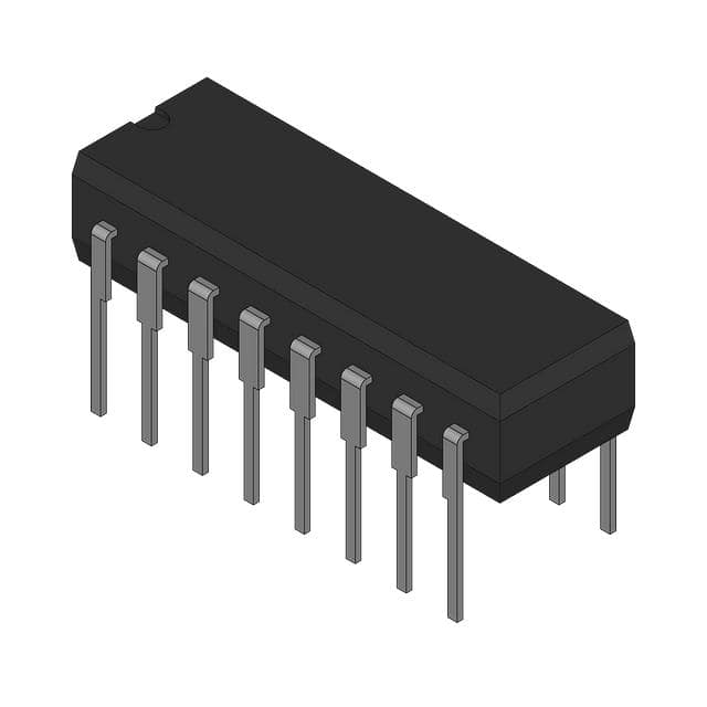
- Part No.:
- ISL8700IBZ
- Manufacturer:
- Renesas
- Category:
- Supervisors
- Package:
- 14-SOIC (0.154", 3.90mm Width)
- Datasheet:
-
 ISL8700IBZ.pdf
- Description:
- IC SUPERVISOR 4 CHANNEL 14SOIC
- Quantity:
- Payment:

- Shipping:

Inventory:3,635
Please send an inquiry. Send us your inquiry, and we will respond immediately.
Product details
Overview
ISL8700IBZ from Intersil is an adjustable quad power supply sequencer IC that monitors a single distributed voltage (2.5V–24V) for undervoltage and overvoltage compliance, then initiates a user-programmed A→B→C→D enable sequence via four open-drain outputs. It uses a 2.6µA TIME pin current source with external capacitor for startup delay, and TB/TC/TD resistors for inter-output delays. It is used in FPGA, DSP, and multi-rail µP systems requiring precise power-up sequencing.
For engineers reviewing the ISL8700IBZ datasheet, ISL8700IBZ pinout, ISL8700IBZ application, or ISL8700IBZ equivalent, key selection considerations include its 2.5V–24V bias range, 1.21V UV/OV threshold accuracy, 100Ω ENABLE output resistance, -40°C to +85°C operation, and SOIC-14 package compatibility with board-level sequencing control.
Technical Context
The ISL8700IBZ implements a voltage-compliance-gated, capacitor-resistor-programmable sequencing engine: UV/OV pins compare divided input voltage against internal 1.21V reference with 104mV hysteresis; only upon valid window detection does the 2.6µA TIME pin current charge an external capacitor to 2.0V threshold, triggering ENABLE_A release.
Subsequent outputs are timed by independent RC-controlled oscillators tied to TB, TC, and TD pins-each resistor sets a discrete delay (e.g., 3kΩ → 4.7ms, 120kΩ → 195ms) between ENABLE transitions, supporting asymmetric on/off timing without firmware or external logic.
Key Specifications
| Parameter | Value and Actual Design Meaning |
|---|---|
| VIN Range | 2.5V to 24V nominal; powers IC and supports wide-input system monitoring without auxiliary bias rail |
| UV/OV Threshold | 1.21V typical; enables precise ±1% trip point setting for 3.3V–24V rails using standard resistor dividers |
| TIME Pin Current | 2.6µA ±10%; provides linear capacitor charging for predictable, temperature-stable startup delay (e.g., 10nF → 7.7ms) |
| ENABLE Output Resistance | 100Ω max; ensures fast rise/fall into typical 4.7kΩ pull-up loads used in DC/DC enable inputs |
| Operating Temp | -40°C to +85°C; validated across full industrial temperature range with no derating required |
| Package | 14-lead SOIC (M14.15); RoHS-compliant, Pb-free, compatible with standard reflow profiles and automated assembly |
Pinout & Package
ISL8700IBZ is housed in a 14-lead SOIC package (JEDEC MO-153, package drawing M14.15), with 1.27mm pitch, 8.65mm × 3.9mm body, and exposed pad not present. Pin 1 is ENABLE_D (active-high open-drain), pin 7 is GND, pin 14 is VIN - all pins match the ISL8700 family pinout exactly per datasheet Figure 2.
| Pin/Terminal | Circuit Role | Design Meaning |
|---|---|---|
| ENABLE_A (Pin 4) | Active-high open-drain sequenced output | First output released after TIME capacitor reaches 2.0V; pulls low if VIN < 1V or UV/OV fault occurs |
| ENABLE_B (Pin 3) | Active-high open-drain sequenced output | Activated after programmable delay set by RTB resistor; tracks ENABLE_A turn-off sequence |
| ENABLE_C (Pin 2) | Active-high open-drain sequenced output | Activated after RTC-set delay; maintains strict A→B→C→D order during both power-up and recovery |
| ENABLE_D (Pin 1) | Active-high open-drain sequenced output | Last output asserted; completes sequence; resets simultaneously with others during UV/OV fault |
| UV (Pin 6) | Undervoltage sense input | Monitors lower rail limit; 1.21V threshold triggers immediate shutdown if input falls below programmed value |
| OV (Pin 5) | Overvoltage sense input | Monitors upper rail limit; 1.21V threshold triggers immediate shutdown if input exceeds programmed value |
| TIME (Pin 10) | Capacitor-based startup delay timer | Sinks 2.6µA to charge external CTIME; delay = C × 2.0V / 2.6µA; discharged automatically after ENABLE_A assertion |
| TB (Pin 11) | Delay programming resistor terminal | Resistor to GND sets delay from ENABLE_A to ENABLE_B activation (e.g., 3kΩ → 4.7ms) |
| TC (Pin 12) | Delay programming resistor terminal | Resistor to GND sets delay from ENABLE_B to ENABLE_C activation (e.g., 51kΩ → 86ms) |
| TD (Pin 13) | Delay programming resistor terminal | Resistor to GND sets delay from ENABLE_C to ENABLE_D activation (e.g., 120kΩ → 195ms) |
| VIN (Pin 14) | Bias supply input | Accepts 2.5V–24V; requires 1µF decoupling; powers internal 3.5V/1.17V regulators and logic |
| GND (Pin 7) | Ground reference | Primary return path for internal regulators, UV/OV comparators, and ENABLE output sinks |
Key Features
| Feature | Design Value |
|---|---|
| Adjustable UV/OV monitoring | Independent resistor-divider configuration enables precise trip points for any rail ≥1.22V, with 104mV hysteresis preventing chatter at thresholds |
| Capacitor-programmed startup delay | 2.6µA constant-current TIME pin allows accurate, temperature-stable delay (±10%) from VIN valid to ENABLE_A assertion |
| Resistor-programmed inter-output delays | Three dedicated pins (TB/TC/TD) accept discrete resistors to set independent delays between ENABLE outputs-no shared timing components |
| Open-drain ENABLE outputs | Each output sinks ≥10mA and presents ≤100Ω on-state resistance, enabling direct interface with standard DC/DC enable inputs (typically 3.3V/5V/12V pull-ups) |
| Full-rail voltage monitoring | Supports monitoring of distributed supplies up to 24V using external divider while operating from same rail-no separate sense supply needed |
Applications
| Server CPU Power Sequencing | FPGA Core/IO Bank Sequencing |
|---|---|
Use Scenario: Multi-phase VRMs powering high-end Xeon or EPYC CPUs require strict VCCIO → VCCSA → VDDQ → VDD sequences with millisecond-level delays and rail monitoring. IC Role / Device Role / Timing Role: ISL8700IBZ acts as autonomous hardware sequencer, replacing FPGA-based or microcontroller-driven timing logic to ensure deterministic, fail-safe startup. Use Value: Eliminates firmware dependency and boot-time latency; guarantees sub-1µs fault response to UV/OV events across all rails monitored via single divider. | Use Scenario: Artix/Kintex Ultrascale+ FPGAs demand staggered power application to core (0.85V), auxiliary (1.8V), and I/O banks (1.2V/1.8V/3.3V) to prevent latch-up or ESD damage. IC Role / Device Role / Timing Role: ISL8700IBZ provides four independently timed, open-drain ENABLE signals-each driving dedicated VRM enable inputs with configurable delays. Use Value: Enables robust, repeatable power-up across temperature and voltage tolerances without recalibration; supports hot-swap-ready designs via VIN transient filtering guidance. |
| Industrial PLC Backplane Power Control | Medical Imaging Subsystem Sequencing |
Use Scenario: Modular PLC chassis with hot-swappable I/O cards require synchronized 5V, 12V, 24V, and isolated analog supply sequencing before card enumeration. IC Role / Device Role / Timing Role: ISL8700IBZ serves as central sequencing supervisor, monitoring backplane 24V and generating timed ENABLEs for downstream DC/DC modules. Use Value: Ensures all subsystems meet IEC 61000-4-5 surge immunity requirements by enforcing minimum hold times and voltage compliance before release. | Use Scenario: CT/MRI subsystems use multiple high-precision ADCs, DACs, and RF transceivers powered from isolated 1.2V, 2.5V, 3.3V, and ±15V rails needing coordinated ramp-up to avoid data corruption. IC Role / Device Role / Timing Role: ISL8700IBZ functions as analog-domain sequencer, interfacing directly with enable pins of medical-grade isolated DC/DC converters. Use Value: Meets IEC 62304 Class C software safety requirements by removing sequencing from software stack-hardware-only fault response under all conditions. |
Equivalent & Alternatives
The following parts are listed as comparable options for similar power supply sequencing applications.
| Alternative Part | Technical Difference | Application Difference | Selection Advice |
|---|---|---|---|
| TPS65023RSLR | Integrated triple-buck + LDO PMIC with fixed 3-output sequencer; no external UV/OV monitoring; 5.5V max VIN | Best for compact, low-voltage (≤5.5V) SoC power trees where sequencing is secondary to regulation | Select ISL8700IBZ when external rail monitoring, >5.5V bias, or fully adjustable delays are required |
| MAX16050ATA+ | Quad sequencer with integrated 12-bit ADC, digital configuration via I²C, 3.6V max VIN, no TIME pin current source | Suited for systems needing telemetry, programmable thresholds, and firmware-controlled sequencing | Select ISL8700IBZ for analog-deterministic, zero-software, high-voltage (>5.5V) sequencing with minimal BOM |
Compared with TPS65023RSLR and MAX16050ATA+, the ISL8700IBZ offers unique support for 24V bias, resistor/capacitor-programmable delays without communication bus overhead, and direct UV/OV monitoring of arbitrary rails-making it optimal for industrial, medical, and high-reliability power-up control where simplicity and voltage range outweigh configurability.
Availability
ISL8700IBZ is available at Aetrix Electronics and suitable for server CPU power sequencing, FPGA core/IO bank sequencing, industrial PLC backplane power control, and medical imaging subsystem sequencing requiring stable component supply across extended temperature and long-lifecycle programs.
Supply support for ISL8700IBZ includes scheduled delivery planning, volume procurement assistance, BOM continuity management, traceable sourcing, and lifecycle availability coordination for OEM customers, industrial embedded developers, connected-device designers, and electronics production programs.
Manufacturer
Intersil Corporation (now part of Renesas Electronics) is a U.S.-based analog and power management IC designer known for high-reliability, precision timing and sequencing solutions targeting industrial, computing, and communications markets.
The ISL8700IBZ belongs to Intersil's adjustable quad sequencer product line, engineered specifically for deterministic, hardware-based power-up/down control in multi-rail systems where firmware-independent reliability and wide-input voltage monitoring are critical.
FAQ
What is the maximum input voltage the ISL8700IBZ can monitor using its UV and OV pins?
The ISL8700IBZ UV and OV pins have a fixed 1.21V threshold, but the device can monitor any distributed voltage ≥1.22V by using an external resistor divider. For example, a 24V rail can be scaled down to 1.21V using Ru=198kΩ, Rm=1.2kΩ, Rl=10kΩ. The datasheet confirms this capability applies to ISL8700IBZ specifically, and the divider design equations are provided on page 6 of FN9250 Rev 2.00. No additional level-shifting circuitry is required.
Does the ISL8700IBZ support power-down sequencing, or only power-up?
The ISL8700IBZ supports only power-up sequencing. Unlike the ISL8702IBZ-which includes SEQ_EN and FAULT pins for controlled shutdown-the ISL8700IBZ lacks those pins and has no provision for reverse-order turn-off. When a UV or OV fault occurs, all four ENABLE outputs reset simultaneously. Datasheet page 4 explicitly states SEQ_EN and FAULT are "not available on ISL8700 and ISL8701", confirming ISL8700IBZ is power-up-only. For bidirectional sequencing, ISL8702IBZ must be selected.
How do I calculate the delay from VIN valid to ENABLE_A assertion for the ISL8700IBZ?
Use the formula CTIME = tVINSEQpd × 770kΩ from datasheet Equation 5 (page 7). For a target delay of 10ms, CTIME = 10ms × 770kΩ = 7.7nF - select a standard 7.5nF or 8.2nF capacitor. This calculation assumes ISL8700IBZ's 2.6µA TIME pin current charging to 2.0V threshold. Measured tVINSEQpd_10 = 7.7ms with 10nF (page 3), validating the linear relationship. Temperature drift is <±5% across -40°C to +85°C per typical curves on page 8.
Can the ISL8700IBZ be used with a 3.3V-only supply, and what layout precautions apply?
Yes, ISL8700IBZ operates down to 2.5V VIN, so 3.3V is fully supported. However, datasheet page 11 warns that low-supply designs require extra noise mitigation: place ≥1µF ceramic decoupling directly at VIN pin, add an RC filter (R <13Ω + C) to suppress dv/dt transients, and route UV/OV traces away from ENABLE outputs to prevent coupling-induced false faults. Adjacent pins ENABLE_A (4) and OV (5) make ground shielding between them essential per Figure 14.
What is the output behavior of ISL8700IBZ ENABLE pins during power-up and fault conditions?
At VIN <1V, all ENABLE outputs are actively pulled low. Once VIN exceeds 2.08V POR threshold, outputs remain latched low until UV >1.21V and OV <1.21V are confirmed; then TIME capacitor charges and ENABLE_A releases high (via external pull-up). During UV/OV fault, all ENABLE outputs immediately return low within 1µs (tshutdown, page 3). This behavior is confirmed for ISL8700IBZ in the Pin Descriptions table (page 4) and Functional Description (page 5).
ISL8700IBZ Specifications
- Product attributes
- Attribute value
- Manufacturer:
- Renesas
- Series:
- -
- Package/Case:
- 14-SOIC (0.154", 3.90mm Width)
- Packaging:
- Tube
- Product Status:
- Obsolete
- Programmable:
- Not Verified
- Type:
- Sequencer
- Number of Voltages Monitored:
- 4
- Voltage - Threshold:
- Adjustable/Selectable
- Output:
- Open Drain or Open Collector
- Reset:
- Active High/Active Low
- Reset Timeout:
- Adjustable/Selectable
- Operating Temperature:
- -40°C ~ 85°C (TA)
- Grade:
- -
- Qualification:
- -
- Mounting Type:
- Surface Mount
- Supplier Device Package:
- 14-SOIC
ISL8700IBZ FAQ
1.How can I place an order for ISL8700IBZ through Aetrix?
Please submit a Request for Quotation (RFQ) for ISL8700IBZ on Aetrix. Our sales agent will provide a competitive quotation and guide you through the order confirmation once you accept the terms.
2.Are the price and stock information for ISL8700IBZ reliable?
The price and inventory of ISL8700IBZ are updated periodically and may fluctuate due to market conditions. Stock and pricing data are typically refreshed every 24 hours. Quotation validity for ISL8700IBZ is usually 5 days.
3.What payment methods are accepted for ISL8700IBZ?
We accept Wire Transfer, PayPal, Credit Card, Western Union, MoneyGram, and Escrow for ISL8700IBZ transactions.
Note: Certain payment methods may incur a processing fee.
4.How is shipping managed for ISL8700IBZ?
ISL8700IBZ orders can be shipped via leading logistics carriers, including DHL, UPS, FedEx, TNT, or Registered Mail.
Once your ISL8700IBZ order is processed, you will receive an email with the shipment details and tracking number.
Note: Tracking information may take up to 24 hours to appear. Express delivery typically takes 3–5 business days.
5.How can I obtain technical support or documentation for ISL8700IBZ?
For technical support, including ISL8700IBZ datasheets, pinout diagrams, or application guidance, please contact our engineering support team. They can provide detailed documentation and assistance for your ISL8700IBZ requirements.
6.How does Aetrix verify that ISL8700IBZ is sourced from the original manufacturer or authorized distributors?
All ISL8700IBZ products on Aetrix are procured from qualified distributors and authorized channels. Our dedicated quality assurance team conducts strict verification, including traceability checks and, if necessary, third-party testing. This ensures that ISL8700IBZ meets industry standards.
7.What is the process for return or replacement of ISL8700IBZ?
All ISL8700IBZ units undergo pre-shipment inspection (PSI). If there is an issue with ISL8700IBZ, returns or replacements are accepted under the following conditions:
1.Quantity discrepancies, incorrect items, or visible external defects (such as breakage or corrosion), acknowledged by Aetrix.
2.The issue is reported within 90 days of delivery.
3.The ISL8700IBZ part is unused and in its original packaging.
Return procedure for ISL8700IBZ:
1.Submit a request within 90 days.
2.Obtain a Return Material Authorization (RMA) from Aetrix.
ISL8700IBZ Tags
-
MIC826SYMT-TR
Microchip Technology

-
APX803S-31SA-7
Diodes Incorporated
-
APX803L20-29SA-7
Diodes Incorporated

-
TPS3828-33DBVR
Texas Instruments

-
V6340RSP3B+
EM Microelectronic
-
EM6325CXSP5B-2.9+
EM Microelectronic
-
MCP120T-300I/TT
Microchip Technology
-
MCP130T-315I/TT
Microchip Technology
-
MCP120T-475I/TT
Microchip Technology
-
MCP111T-300E/TT
Microchip Technology
-
MCP120T-315I/TT
Microchip Technology
-
MCP809T-315I/TT
Microchip Technology
Tech Hub

TTL and CMOS logic families differ in thresholds, loading, output drive, power and timing. This engineering guide compares 74HC and 74HCT, calculates noise margins and checks 3.3 V/5 V compatibility.

A practical engineering guide to 3.3V and 5V logic compatibility, input thresholds, resistor dividers, translator ICs, MOSFET level shifting, I2C pull-ups, timing limits and power-sequencing risks.

The 74HC595 uses push-pull logic outputs, while the TPIC6B595 uses 50 V open-drain DMOS sinks for higher-power loads. This guide compares timing, current limits, 3.3 V interfacing, load wiring, thermal…

The 74HC595 converts serial data into eight stable parallel outputs. This guide covers pin functions, shift and storage timing, OE and MR behavior, drive-current limits, cascading, voltage compatibilit…

A technical comparison of level-sensitive latches and edge-triggered flip-flops, covering timing windows, setup and hold limits, master–slave operation, time borrowing, race-through, HDL inference and…

A D latch stores one bit while Enable controls when data can pass. This reference covers gate-level operation, truth tables, transparency, setup and hold timing, LE versus OE, common ICs and practical …

An SR latch stores one bit through cross-coupled feedback. This engineering reference covers NOR and NAND implementations, truth tables, forbidden-state recovery, gated operation, switch debouncing, fa…

Latch circuits retain one bit through feedback. This technical reference covers SR and D latches, truth tables, transparency, timing limits, latch-versus-flip-flop behavior, applications and common log…

An engineering guide to LED driver operation, constant-current and constant-voltage outputs, linear and switching topologies, dimming, IC selection, calculations, replacement compatibility, and fault c…

Operational amplifier guide covering op amp basics, feedback, ideal vs real op amps, common configurations, buffer circuits, offset, bias current, gain-bandwidth, slew rate, rail-to-rail limits and sel…


