
 My Inquiry
 My Account


NXP Semiconductors JN5169/001Z
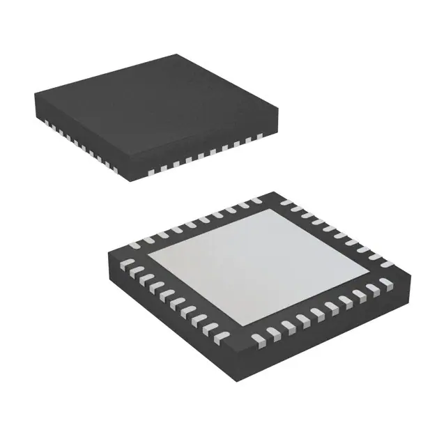
- Part No.:
- JN5169/001Z
- Manufacturer:
- NXP Semiconductors
- Category:
- RF Transceiver ICs
- Package:
- 40-VFQFN Exposed Pad
- Datasheet:
-
 JN5169/001Z.pdf
- Description:
- IC RF TXRX+MCU 802.15.4 40HVQFN
- Quantity:
- Payment:

- Shipping:

Inventory:675
Please send an inquiry. Send us your inquiry, and we will respond immediately.
Product details
Overview
JN5169/001Z from NXP Semiconductors is a 32-bit IEEE 802.15.4-compliant wireless microcontroller for ZigBee PRO, Smart Energy, Light Link, and Home Automation applications. It integrates a 2.4 GHz transceiver (−96 dBm sensitivity, +10 dBm max TX), 512 kB Flash, 32 kB RAM, 4 kB EEPROM, and 20 DIO pins in a 6 × 6 mm HVQFN40 package. Designed for coin-cell operation, it achieves 13 mA RX current and 50 nA deep sleep current.
For engineers reviewing the JN5169/001Z datasheet, JN5169/001Z pinout, JN5169/001Z application, or JN5169/001Z equivalent, key selection criteria include integrated AES-128 security, antenna diversity support, programmable 1–32 MHz CPU clock, 6-channel 10-bit ADC with battery/temperature sensing, and ZigBee stack compatibility without external memory.
Technical Context
The JN5169/001Z implements a unified-memory 32-bit RISC CPU with variable-width instructions and multi-stage pipeline, enabling concurrent execution of ZigBee PRO stack layers and user application code. Its radio subsystem includes MAC accelerator (CRC, auto-ACK, address check), baseband controller, and hardware AES-CCM coprocessor compliant with IEEE 802.15.4-2006.
Power management integrates ultra-low-power RC oscillators (0.7 µA sleep timer), deep-sleep mode (50 nA wake-up from I/O), and five configurable voltage regulators (VB_DIG, VB_SYNTH, VB_VCO, VB_RF1/VB_RF2, VDDA/VDDD). Analog peripherals include internal temperature sensor, battery monitor, and comparator inputs shared with DIO16/DIO17.
Key Specifications
| Parameter | Value and Actual Design Meaning |
|---|---|
| CPU Core | 32-bit RISC with 1–32 MHz programmable clock; enables dynamic power/performance scaling for battery lifetime optimization |
| Radio Compliance | IEEE 802.15.4-2006 PHY/MAC; supports ZigBee PRO, Smart Energy, Light Link, and Home Automation profiles out-of-box |
| RX Sensitivity | −96 dBm; ensures robust link budget (106 dB) and reliable reception in noisy 2.4 GHz ISM band environments |
| TX Output Power | Configurable up to +10 dBm (23.3 mA); enables long-range communication without external PA |
| Memory | 512 kB Flash (10k write cycles), 32 kB RAM, 4 kB EEPROM; supports OTA firmware updates without external storage |
| ADC | 6-channel 10-bit ADC with dedicated battery/temperature sensors; eliminates need for discrete monitoring ICs |
| Security | Hardware 128-bit AES-CCM engine; accelerates encryption/authentication per IEEE 802.15.4 without CPU overhead |
| Package | HVQFN40, 6 × 6 × 0.85 mm, lead-free/RoHS; surface-mount compatible with high-density IoT PCB layouts |
Pinout & Package
HVQFN40 package: 40-terminal, thermally enhanced, very thin quad flat no-lead construction with exposed die paddle (VSSA) requiring PCB thermal pad connection per Section 15.1 layout rules.
| Pin/Terminal | Circuit Role | Design Meaning |
|---|---|---|
| RF_IO (Pin 13) | Single-ended RF antenna interface | Direct connection to 50 Ω microstrip; requires two inductors and two capacitors for impedance matching per datasheet Figure 48 |
| XTAL_IN / XTAL_OUT (Pins 5/4) | 32 MHz crystal oscillator terminals | Drives system clock; divided to 16 MHz core clock; requires external load capacitors to analog ground |
| VDDA / VDDD (Pins 9/30) | Analog/digital supply rails | Each requires 100 nF ceramic decoupling; VDDA powers ADC/comparator, VDDD powers CPU/peripherals |
| DIO0–DIO19 (Pins 16–20, 26–40) | Multi-function digital I/O | 20 pins support GPIO, UART, SPI, I²C, PWM, timers, JTAG, antenna diversity (ADO/ADE), and ADC inputs |
| RESET_N (Pin 3) | Active-low reset input | Internally pulled up to 500 kΩ; assertion resets CPU, radio, and peripherals; must meet 100 ms VDD ramp requirement |
| VB_RF1 / VB_RF2 (Pins 14/12) | RF power supply regulators | Must be shorted externally near device; require 100 nF + 47 pF decoupling for stable RF performance |
Key Features
| Feature | Design Value |
|---|---|
| Integrated ZigBee PRO stack | Pre-certified Home Automation, Light Link, and Smart Energy profiles reduce time-to-market and eliminate protocol stack development effort |
| Antenna diversity with Auto RX | Hardware-based switching between two antennas based on received energy detection improves link reliability in multipath environments |
| Ultra-low-power sleep modes | 0.7 µA sleep timer current and 50 nA deep sleep enable >10-year coin-cell operation in periodic sensor reporting applications |
| On-chip analog monitoring | Battery voltage and die temperature sensors feed directly into ADC channels, eliminating external BMS components |
| Flexible peripheral routing | 20 DIO pins with overlapping functions (e.g., DIO12 = PWM2/CTS0/JTAG_TCK/ADO/SPISMOSI) simplify PCB layout and design reuse |
| Hardware MAC acceleration | Dedicated logic handles CRC generation, address filtering, auto-ACK, and packet timing-offloading CPU and ensuring deterministic latency |
Applications
| ZigBee Smart Energy Metering | ZigBee Light Link Dimmer Switch |
|---|---|
Use Scenario: Wireless electricity/gas/water meter transmitting consumption data hourly to utility concentrator via ZigBee Smart Energy profile. IC Role / Device Role / Timing Role: Primary wireless MCU handling IEEE 802.15.4 PHY/MAC, ZigBee SE stack, secure AES-encrypted payload assembly, and low-duty-cycle sleep/wake scheduling. Use Value: 50 nA deep sleep and 13 mA RX current enable 10+ year battery life on CR2032; integrated EEPROM stores billing history without external memory. | Use Scenario: Battery-powered wall-mounted dimmer switch controlling LED fixtures via ZigBee Light Link network with touch/capacitive interface. IC Role / Device Role / Timing Role: Dual-role node acting as both Light Link controller (initiating scenes) and end device (receiving commands); manages capacitive touch matrix (up to 40 keys) and PWM dimming output. Use Value: On-chip 6-channel ADC reads touch electrodes and battery level; 4× PWM timers drive smooth LED dimming; 0.7 µA sleep timer maintains instant wake-on-touch response. |
| ZigBee Home Automation Thermostat | Energy-Harvesting Wireless Sensor Node |
Use Scenario: HVAC thermostat using ambient temperature readings and occupancy detection to optimize heating/cooling cycles over ZigBee HA network. IC Role / Device Role / Timing Role: Sensor fusion hub integrating internal temperature sensor, external thermistor ADC inputs, and wireless command parsing; executes local control logic while relaying status to gateway. Use Value: Internal temperature sensor calibrated across −40 °C to +125 °C eliminates calibration drift; 2-wire I²C interface connects to external humidity/occupancy sensors with minimal BOM cost. | Use Scenario: Self-powered light switch harvesting mechanical energy to trigger BLE/ZigBee beacon transmission upon press, powered by piezoelectric or RF harvesting circuit. IC Role / Device Role / Timing Role: Ultra-low-power event-driven transmitter: wakes only on harvest-triggered interrupt, configures radio, sends encrypted packet, then returns to 50 nA deep sleep. Use Value: Deep sleep current <50 nA allows energy harvesting circuits to accumulate sufficient charge between events; integrated AES ensures secure command transmission without external crypto IC. |
Equivalent & Alternatives
The following parts are listed as comparable options for similar wireless microcontroller applications.
| Alternative Part | Technical Difference | Application Difference | Selection Advice |
|---|---|---|---|
| JN5179/001Z | Successor with 1 MB Flash, 64 kB RAM, improved RX sensitivity (−100 dBm), and Bluetooth LE 5.0 dual-mode support | Required for new designs targeting ZigBee 3.0 + BLE interoperability or larger firmware images | Select JN5179/001Z when migrating to next-gen ZigBee 3.0 stacks or adding BLE coexistence; JN5169/001Z remains optimal for cost-sensitive legacy ZigBee PRO deployments |
| CC2652R1F | Texas Instruments SimpleLink device with 352 kB Flash, 80 kB RAM, Sub-1 GHz + 2.4 GHz dual-band, and TI-RTOS SDK | Preferred for multi-protocol (ZigBee + Thread + BLE) or Sub-1 GHz long-range requirements | Choose CC2652R1F if Sub-1 GHz operation or TI's ecosystem (Code Composer Studio, SysConfig) is required; JN5169/001Z offers lower BOM cost for pure 2.4 GHz ZigBee PRO |
Compared with JN5169/001Z, JN5179/001Z delivers higher memory capacity and dual-mode radio flexibility at increased cost and power, while CC2652R1F provides broader protocol support and stronger toolchain integration but requires different software architecture and layout practices.
Availability
JN5169/001Z is available at Aetrix Electronics and suitable for ZigBee Smart Energy metering, Light Link dimmer switches, and Home Automation thermostats requiring stable component supply throughout product lifecycles.
Supply support for JN5169/001Z includes scheduled delivery planning, volume procurement assistance, BOM continuity management, traceable sourcing, and lifecycle availability coordination for OEM customers, industrial embedded developers, connected-device designers, and electronics production programs.
Manufacturer
NXP Semiconductors is a global semiconductor leader specializing in secure connectivity solutions for automotive, industrial, and IoT markets, with headquarters in Eindhoven, Netherlands.
The JN5169/001Z belongs to NXP's JN51xx ZigBee wireless MCU family, engineered specifically for ultra-low-power, standards-compliant mesh networking in battery-operated smart home and utility infrastructure devices.
FAQ
What is the maximum transmit power and corresponding current draw for JN5169/001Z?
The JN5169/001Z supports configurable TX output power up to +10 dBm, drawing 23.3 mA at that setting. Lower power levels include 8.5 dBm (19.6 mA) and 3 dBm (14 mA). These values are measured under standard 2.4 GHz ISM band conditions with proper RF matching per datasheet layout guidelines. The JN5169/001Z does not require external power amplifiers to achieve these outputs.
Does JN5169/001Z support over-the-air (OTA) firmware updates without external memory?
Yes, JN5169/001Z supports full OTA firmware updates using its embedded 512 kB Flash memory. The device includes dedicated boot code region (8 kB) and application region (512 kB), with guaranteed 10,000 write cycles and 10-year data retention. No external Flash or EEPROM is needed, reducing BOM count and PCB area. The JN5169/001Z firmware update mechanism is integrated into NXP's ZigBee PRO stack libraries.
How many digital I/O pins does JN5169/001Z provide, and what peripheral functions do they support?
JN5169/001Z provides 20 dedicated DIO pins (DIO0–DIO19), each supporting multiple functions including GPIO, UART (2 ports), SPI master/slave, I²C master/slave, PWM (5 channels), timers, JTAG debug, antenna diversity signals (ADO/ADE), and ADC inputs. Pins like DIO12 and DIO13 are multi-functional (e.g., DIO12 = PWM2/CTS0/JTAG_TCK/ADO/SPISMOSI), allowing flexible peripheral mapping in constrained layouts. The JN5169/001Z datasheet Table 2 details all pin assignments.
What is the operating temperature range and supply voltage specification for JN5169/001Z?
JN5169/001Z operates from −40 °C to +125 °C and accepts a single 2.0 V to 3.6 V supply across VDDA and VDDD pins. This wide voltage range supports direct coin-cell (e.g., CR2032) and alkaline battery operation without external regulators. The JN5169/001Z internal 1.8 V regulators (VB_DIG, VB_SYNTH, etc.) are optimized for internal use only and must not power external circuitry.
Is JN5169/001Z pin-compatible with other members of the JN51xx family, such as JN5164 or JN5168?
No, JN5169/001Z is not pin-compatible with JN5164 or JN5168. While sharing the HVQFN40 package footprint, pin functions differ significantly-for example, JN5169/001Z assigns RF_IO to Pin 13 and includes dedicated antenna diversity outputs (ADO/ADE) absent in earlier variants. Migration requires PCB layout revision and firmware adaptation. The JN5169/001Z datasheet explicitly states its pinout is unique to this generation.
JN5169/001Z Specifications
- Product attributes
- Attribute value
- Manufacturer:
- NXP Semiconductors
- Series:
- -
- Package/Case:
- 40-VFQFN Exposed Pad
- Packaging:
- Tape & Reel (TR)
- Product Status:
- Active
- Programmable:
- Not Verified
- Type:
- TxRx + MCU
- RF Family/Standard:
- 802.15.4
- Protocol:
- Zigbee®
- Modulation:
- O-QPSK
- Frequency:
- 2.4GHz
- Data Rate (Max):
- 400kbps
- Power - Output:
- 10dBm
- Sensitivity:
- -96.5dBm
- Memory Size:
- 512kB Flash, 4kB EEPROM, 32kB RAM
- Serial Interfaces:
- I2C, JTAG, SPI, UART
- GPIO:
- 20
- Voltage - Supply:
- 2V ~ 3.6V
- Current - Receiving:
- 13mA ~ 15mA
- Current - Transmitting:
- 14mA ~ 23.3mA
- Operating Temperature:
- -40°C ~ 125°C
- Grade:
- -
- Qualification:
- -
- Supplier Device Package:
- 40-HVQFN (6x6)
JN5169/001Z FAQ
1.How can I place an order for JN5169/001Z through Aetrix?
Please submit a Request for Quotation (RFQ) for JN5169/001Z on Aetrix. Our sales agent will provide a competitive quotation and guide you through the order confirmation once you accept the terms.
2.Are the price and stock information for JN5169/001Z reliable?
The price and inventory of JN5169/001Z are updated periodically and may fluctuate due to market conditions. Stock and pricing data are typically refreshed every 24 hours. Quotation validity for JN5169/001Z is usually 5 days.
3.What payment methods are accepted for JN5169/001Z?
We accept Wire Transfer, PayPal, Credit Card, Western Union, MoneyGram, and Escrow for JN5169/001Z transactions.
Note: Certain payment methods may incur a processing fee.
4.How is shipping managed for JN5169/001Z?
JN5169/001Z orders can be shipped via leading logistics carriers, including DHL, UPS, FedEx, TNT, or Registered Mail.
Once your JN5169/001Z order is processed, you will receive an email with the shipment details and tracking number.
Note: Tracking information may take up to 24 hours to appear. Express delivery typically takes 3–5 business days.
5.How can I obtain technical support or documentation for JN5169/001Z?
For technical support, including JN5169/001Z datasheets, pinout diagrams, or application guidance, please contact our engineering support team. They can provide detailed documentation and assistance for your JN5169/001Z requirements.
6.How does Aetrix verify that JN5169/001Z is sourced from the original manufacturer or authorized distributors?
All JN5169/001Z products on Aetrix are procured from qualified distributors and authorized channels. Our dedicated quality assurance team conducts strict verification, including traceability checks and, if necessary, third-party testing. This ensures that JN5169/001Z meets industry standards.
7.What is the process for return or replacement of JN5169/001Z?
All JN5169/001Z units undergo pre-shipment inspection (PSI). If there is an issue with JN5169/001Z, returns or replacements are accepted under the following conditions:
1.Quantity discrepancies, incorrect items, or visible external defects (such as breakage or corrosion), acknowledged by Aetrix.
2.The issue is reported within 90 days of delivery.
3.The JN5169/001Z part is unused and in its original packaging.
Return procedure for JN5169/001Z:
1.Submit a request within 90 days.
2.Obtain a Return Material Authorization (RMA) from Aetrix.
JN5169/001Z Tags

-
ESP32-D0WD-V3
Espressif Systems

-
ESP8266EX
Espressif Systems

-
ESP32-S3
Espressif Systems

-
NRF24L01P-R7
Nordic Semiconductor ASA
-
NRF24L01P-R
Nordic Semiconductor ASA

-
ESP32-U4WDH
Espressif Systems

-
DA14531-00000OG2
Renesas
-
ESP32-C6FH4
Espressif Systems

-
DA14531-00000FX2
Renesas
-
NRF24L01P-T
Nordic Semiconductor ASA

-
NRF52810-QCAA-R
Nordic Semiconductor ASA
-
ESP32-S3FN8
Espressif Systems
Tech Hub

A practical engineering guide to 3.3V and 5V logic compatibility, input thresholds, resistor dividers, translator ICs, MOSFET level shifting, I2C pull-ups, timing limits and power-sequencing risks.

The 74HC595 uses push-pull logic outputs, while the TPIC6B595 uses 50 V open-drain DMOS sinks for higher-power loads. This guide compares timing, current limits, 3.3 V interfacing, load wiring, thermal…

The 74HC595 converts serial data into eight stable parallel outputs. This guide covers pin functions, shift and storage timing, OE and MR behavior, drive-current limits, cascading, voltage compatibilit…

A technical comparison of level-sensitive latches and edge-triggered flip-flops, covering timing windows, setup and hold limits, master–slave operation, time borrowing, race-through, HDL inference and…

A D latch stores one bit while Enable controls when data can pass. This reference covers gate-level operation, truth tables, transparency, setup and hold timing, LE versus OE, common ICs and practical …

An SR latch stores one bit through cross-coupled feedback. This engineering reference covers NOR and NAND implementations, truth tables, forbidden-state recovery, gated operation, switch debouncing, fa…

Latch circuits retain one bit through feedback. This technical reference covers SR and D latches, truth tables, transparency, timing limits, latch-versus-flip-flop behavior, applications and common log…

An engineering guide to LED driver operation, constant-current and constant-voltage outputs, linear and switching topologies, dimming, IC selection, calculations, replacement compatibility, and fault c…

Operational amplifier guide covering op amp basics, feedback, ideal vs real op amps, common configurations, buffer circuits, offset, bias current, gain-bandwidth, slew rate, rail-to-rail limits and sel…

Jumper cables guide covering safe connection order, red and black clamp placement, final ground connection, cable gauge, length, clamp quality, copper vs CCA cables, jump starter comparison and battery…


