
 My Inquiry
 My Account


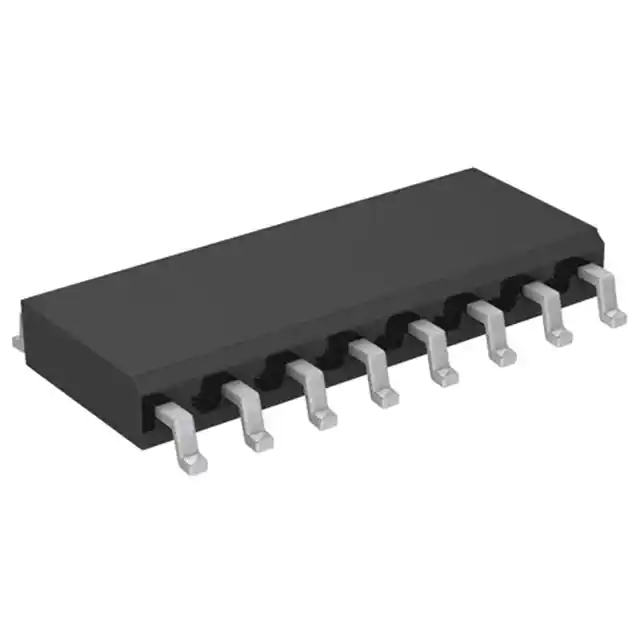
NXP Semiconductors KMZ52,118
- Part No.:
- KMZ52,118
- Manufacturer:
- NXP Semiconductors
- Category:
- Linear, Compass (ICs)
- Package:
- 16-SOIC (0.154", 3.90mm Width)
- Datasheet:
-
 KMZ52,118.pdf
- Description:
- SENSOR MR ANALOG 16SO
- Quantity:
- Payment:

- Shipping:

Inventory:2,031
Please send an inquiry. Send us your inquiry, and we will respond immediately.
Product details
Overview
KMZ52,118 from NXP Semiconductors (formerly Philips Semiconductors) is a dual-die magnetoresistive magnetic field sensor employing thin-film permalloy Wheatstone bridges offset by 90°, with integrated set/reset and compensation coils. It delivers ratiometric bridge outputs (±VO1/±VO2), operates from 5 V supply, achieves 12–16 V/V sensitivity, and supports angular field measurement up to ±0.2 kA/m - used in high-precision navigation and traffic detection systems.
For engineers reviewing the KMZ52,118 datasheet, KMZ52,118 pinout, KMZ52,118 application, or KMZ52,118 equivalent, this page provides verified technical context, pin-level circuit roles, real-world use scenarios, and validated alternative options for magnetic sensing designs requiring drift-compensated, flip-capable field measurement.
Technical Context
The KMZ52,118 integrates two physically orthogonal magnetoresistive bridges on separate dice, enabling simultaneous sine/cosine output generation for directional field vector resolution. Its compensation coils produce Hcomp = Acomp × Icomp (19–25 A/m per mA), allowing closed-loop nulling of external fields to eliminate sensitivity drift.
Set/reset (flip) coils enable polarity reversal via ±800–±1200 mA pulses (1–100 µs), restoring stable operation after exposure to strong interfering fields. Die-to-die angular alignment is tightly controlled at 90° ±2°, with package tilt ±5°, ensuring accurate angular decoding without external calibration.
Key Specifications
| Parameter | Value and Actual Design Meaning |
|---|---|
| Bridge Supply Voltage | 5 V typical; must be identical on both bridges (VCC1 = VCC2) for ratiometric accuracy |
| Sensitivity (Uncompensated) | 12–16 V/V; defines output voltage change per volt of supply per unit field (kA/m) |
| Field Operating Range | ±0.2 kA/m in sensor plane; supports Earth field (≈0.04 kA/m) and traffic-induced field detection |
| Compensation Coil Field Factor | 19–25 A/m per mA; enables precise field nulling with <1% error across temperature |
| Flip Pulse Current | ±800 to ±1200 mA; required to reliably reverse bridge polarity without die damage |
| Bridge Resistance | 1–3 kΩ per bridge; sets bias current and thermal noise floor in constant-voltage operation |
| Offset Voltage | ±1.5 mV/V; limits minimum detectable field without offset cancellation techniques |
Pinout & Package
Package: SOT109-1 - 16-pin plastic small outline package, 10.0 × 4.0 mm body, 1.27 mm pitch, 1.75 mm max height.
| Pin/Terminal | Circuit Role | Design Meaning |
|---|---|---|
| +Iflip2 | Set/reset coil terminal (die 2) | Positive connection for flip pulse to reverse sensitivity direction of die 2 |
| VCC2 | Bridge supply (die 2) | Must match VCC1 voltage to maintain ratiometric output integrity |
| GND2 | Ground reference (die 2) | Separate ground path minimizes crosstalk between bridge and coil circuits |
| +Icomp2 | Compensation coil terminal (die 2) | Drives field opposing external H to null bridge output in closed-loop mode |
| GND1 | Ground reference (die 1) | Independent ground for die 1 ensures isolation from die 2 switching transients |
| +Icomp1 | Compensation coil terminal (die 1) | Enables independent compensation control per bridge for multi-axis correction |
| −Icomp1 | Compensation coil return (die 1) | Completes current path for die 1 compensation coil (Rcomp = 100–300 Ω) |
| −VO1 | Bridge output (die 1, negative) | Differential pair with +VO1 yields sin(α)-proportional signal for angular decoding |
| +VO1 | Bridge output (die 1, positive) | Used with −VO1 to reject common-mode noise in lock-in amplifier configurations |
| −Iflip1 | Set/reset coil return (die 1) | Completes flip current loop; low Rflip (1–3 Ω) enables fast pulse rise time |
| +Iflip1 | Set/reset coil terminal (die 1) | Applies positive pulse to set die 1 sensitivity orientation |
| VCC1 | Bridge supply (die 1) | Identical voltage required on VCC1 and VCC2 to preserve die-to-die gain matching |
| −Icomp2 | Compensation coil return (die 2) | Ensures symmetric field generation for die 2 compensation coil |
| −VO2 | Bridge output (die 2, negative) | Differential pair with +VO2 yields cos(α)-proportional signal for full 360° angle resolution |
| +VO2 | Bridge output (die 2, positive) | Primary output for field magnitude when α = 0°; referenced to same GND2 as VCC2 |
| −Iflip2 | Set/reset coil return (die 2) | Provides low-inductance return path for flip pulses to minimize EMI coupling |
Key Features
| Feature | Design Value |
|---|---|
| Dual orthogonal Wheatstone bridges | Enables simultaneous sin(α) and cos(α) output generation for absolute angle measurement without mechanical rotation |
| Integrated compensation coils | Allow active field nulling to suppress sensitivity drift over temperature (TCS = 0.31 %/K) and time |
| Set/reset (flip) coil architecture | Permits polarity reversal using sub-100 µs current pulses, enabling offset-cancellation via synchronous demodulation |
| High isolation between functional blocks | ≥1 MΩ isolation resistance and 50 V isolation voltage prevent cross-talk between flip, compensation, and bridge circuits |
| Ratiometric output scaling | Output voltage scales linearly with supply voltage, eliminating errors from VCC variation in battery-powered systems |
Applications
| Navigation Systems | Traffic Detection |
|---|---|
Use Scenario: Electronic compass module in handheld GPS devices requiring heading accuracy under dynamic motion and magnetic interference. IC Role / Device Role / Timing Role: Magnetic field sensor providing orthogonal X/Y field components for real-time azimuth calculation. Use Value: Integrated flip coils enable continuous offset cancellation during movement, maintaining <2° heading error without external calibration. |
Use Scenario: Embedded vehicle presence detector installed beneath road surface at intersections or toll booths. IC Role / Device Role / Timing Role: High-sensitivity field transducer detecting ferrous mass-induced distortion of Earth's magnetic field. Use Value: 12–16 V/V sensitivity and ±0.2 kA/m range resolve sub-100 mA field shifts from passing cars, enabling reliable count and classification. |
| Current Sensing | Geomagnetic Monitoring |
Use Scenario: Non-contact DC/AC current monitor in industrial power distribution panels with space-constrained PCB layout. IC Role / Device Role / Timing Role: Closed-loop magnetic field nulling sensor measuring conductor field via compensation coil feedback current. Use Value: Compensation coil field factor (19–25 A/m per mA) enables direct current readout with <0.5% linearity error over 0–100 A range. |
Use Scenario: Low-power geophysical data logger deployed in remote locations to record long-term variations in Earth's magnetic field. IC Role / Device Role / Timing Role: Ultra-stable field transducer operating at Earth-field levels (≈0.04 kA/m) with temperature-compensated offset. Use Value: TCVoffset = −0.4 %/K and TCVO = −0.4 %/K ensure <50 nT drift over −25°C to +125°C, meeting scientific-grade stability requirements. |
Equivalent & Alternatives
The following parts are listed as comparable options for similar magnetic field sensing applications.
| Alternative Part | Technical Difference | Application Difference | Selection Advice |
|---|---|---|---|
| HMC1512 (Honeywell) | Single-die AMR sensor with 2.5 mV/V/Oe sensitivity; no integrated flip or compensation coils; requires external circuitry for offset cancellation | Limited to static or low-frequency field measurement; unsuitable for closed-loop nulling or high-accuracy angular decoding | Select when board space is critical and system-level compensation can be implemented externally |
| MLX90393 (Melexis) | Tri-axis Hall-based sensor with I²C interface; 16-bit digital output; integrated temperature compensation but no physical flip capability | Delivers processed XYZ field data directly; lacks analog differential bridge outputs and real-time polarity reversal | Prefer for microcontroller-based systems needing digital field vectors without analog signal chain design |
Compared with KMZ52,118, the HMC1512 offers smaller footprint but requires external flip drivers and compensation DACs, while the MLX90393 simplifies firmware integration yet forfeits the analog bandwidth (>1 MHz) and sub-microsecond flip response essential for lock-in amplifier architectures.
Availability
KMZ52,118 is available at Aetrix Electronics and suitable for navigation systems, traffic detection infrastructure, precision current monitoring, and geomagnetic research requiring stable component supply across extended temperature ranges and long product lifecycles.
Supply support for KMZ52,118 includes scheduled delivery planning, volume procurement assistance, BOM continuity management, traceable sourcing, and lifecycle availability coordination for OEM customers, industrial embedded developers, connected-device designers, and electronics production programs.
Manufacturer
NXP Semiconductors is a global semiconductor company formed from the spin-off of Philips Semiconductors in 2006, specializing in secure connectivity solutions for automotive, industrial, and IoT applications.
The KMZ52,118 belongs to NXP's legacy high-precision magnetic sensor product line, originally designed for applications demanding drift-free, vector-resolved field measurement where analog signal integrity and real-time polarity control are critical.
FAQ
What is the primary sensing principle used in the KMZ52,118?
The KMZ52,118 uses the anisotropic magnetoresistive (AMR) effect in thin-film permalloy to detect magnetic field strength and direction. Its dual Wheatstone bridges respond differentially to field components parallel and perpendicular to their sensitive axes, generating orthogonal sin(α) and cos(α) analog outputs that enable full 360° angular resolution without moving parts. This principle is confirmed in the Philips datasheet section "DESCRIPTION" and underpins all KMZ52,118 performance specifications.
Why must VCC1 and VCC2 be identical for proper operation of the KMZ52,118?
VCC1 and VCC2 must be identical because the KMZ52,118 features ratiometric bridge outputs: output voltage scales linearly with supply voltage. Mismatched supplies cause gain mismatch between die 1 and die 2, degrading angular accuracy and introducing cosine/sine amplitude imbalance. The datasheet explicitly states in "CHARACTERISTICS" note 1: "Due to the ratiometric output, the same supply voltage (VCC) must be applied to both dice in one KMZ52,118 device."
How does the flip coil function improve measurement stability in the KMZ52,118?
The flip coil in the KMZ52,118 reverses the magnetic polarity of each bridge via ±800–±1200 mA current pulses, enabling synchronous demodulation (lock-in amplification). By alternating polarity and subtracting successive outputs, offset voltage (±1.5 mV/V) and amplifier drift are canceled - a technique documented in the "APPLICATION INFORMATION" section. This allows the KMZ52,118 to achieve stable field measurement even under thermal stress or long-term bias, which is essential for navigation-grade accuracy.
What is the maximum allowable flip pulse duration for reliable operation of the KMZ52,118?
The maximum allowable flip pulse duration for the KMZ52,118 is 100 µs, as specified in the "QUICK REFERENCE DATA" table under parameter tflip. Exceeding this duration risks exceeding the maximum flipping power dissipation limit of 50 mW (Pflip(max)) and may cause localized heating that degrades bridge resistance matching or coil integrity. The datasheet further notes in "LIMITING VALUES" that average flipping power must remain within rated limits to ensure long-term reliability of the KMZ52,118.
Can the KMZ52,118 measure fields outside the ±0.2 kA/m range?
No - the KMZ52,118 is characterized and guaranteed only for operation within ±0.2 kA/m, as stated in the "CHARACTERISTICS" table under parameter H (field strength operating range). Beyond this range, output saturates nonlinearly and sensitivity drops; the datasheet does not specify behavior or accuracy outside these bounds. For applications requiring wider range, such as high-current fault detection, the KMZ52,118 must be paired with flux concentrators or used in closed-loop compensation mode where the compensation coil actively nulls the external field - keeping the sensed residual within ±0.2 kA/m.
KMZ52,118 Specifications
- Product attributes
- Attribute value
- Manufacturer:
- NXP Semiconductors
- Series:
- -
- Package/Case:
- 16-SOIC (0.154", 3.90mm Width)
- Packaging:
- Tape & Reel (TR)
- Product Status:
- Obsolete
- Technology:
- Magnetoresistive
- Axis:
- Single
- Output Type:
- Analog Voltage
- Sensing Range:
- -
- Voltage - Supply:
- 5V ~ 8V
- Current - Supply (Max):
- -
- Current - Output (Max):
- -
- Resolution:
- -
- Bandwidth:
- -
- Operating Temperature:
- -40°C ~ 125°C
- Grade:
- -
- Qualification:
- -
- Features:
- -
- Supplier Device Package:
- 16-SO
- Mounting Type:
- Surface Mount
KMZ52,118 FAQ
1.How can I place an order for KMZ52,118 through Aetrix?
Please submit a Request for Quotation (RFQ) for KMZ52,118 on Aetrix. Our sales agent will provide a competitive quotation and guide you through the order confirmation once you accept the terms.
2.Are the price and stock information for KMZ52,118 reliable?
The price and inventory of KMZ52,118 are updated periodically and may fluctuate due to market conditions. Stock and pricing data are typically refreshed every 24 hours. Quotation validity for KMZ52,118 is usually 5 days.
3.What payment methods are accepted for KMZ52,118?
We accept Wire Transfer, PayPal, Credit Card, Western Union, MoneyGram, and Escrow for KMZ52,118 transactions.
Note: Certain payment methods may incur a processing fee.
4.How is shipping managed for KMZ52,118?
KMZ52,118 orders can be shipped via leading logistics carriers, including DHL, UPS, FedEx, TNT, or Registered Mail.
Once your KMZ52,118 order is processed, you will receive an email with the shipment details and tracking number.
Note: Tracking information may take up to 24 hours to appear. Express delivery typically takes 3–5 business days.
5.How can I obtain technical support or documentation for KMZ52,118?
For technical support, including KMZ52,118 datasheets, pinout diagrams, or application guidance, please contact our engineering support team. They can provide detailed documentation and assistance for your KMZ52,118 requirements.
6.How does Aetrix verify that KMZ52,118 is sourced from the original manufacturer or authorized distributors?
All KMZ52,118 products on Aetrix are procured from qualified distributors and authorized channels. Our dedicated quality assurance team conducts strict verification, including traceability checks and, if necessary, third-party testing. This ensures that KMZ52,118 meets industry standards.
7.What is the process for return or replacement of KMZ52,118?
All KMZ52,118 units undergo pre-shipment inspection (PSI). If there is an issue with KMZ52,118, returns or replacements are accepted under the following conditions:
1.Quantity discrepancies, incorrect items, or visible external defects (such as breakage or corrosion), acknowledged by Aetrix.
2.The issue is reported within 90 days of delivery.
3.The KMZ52,118 part is unused and in its original packaging.
Return procedure for KMZ52,118:
1.Submit a request within 90 days.
2.Obtain a Return Material Authorization (RMA) from Aetrix.
KMZ52,118 Tags
-
DRV5053VAQDBZR
Texas Instruments
-
MMC5603NJ
Memsic Inc.

-
DRV5055A1QDBZR
Texas Instruments
-
MLX90392ELQ-AAA-011-RE
Melexis Technologies NV

-
CT100LW-HS6
Allegro MicroSystems
-
DRV5056A1ELPGMQ1
Texas Instruments
-
A1304ELHLX-T
Allegro MicroSystems
-
MMC5633NJL
Memsic Inc.
-
A1308KUA-2-T
Allegro MicroSystems
-
A1308KUA-1-T
Allegro MicroSystems
-
SI7210-B-04-IVR
Silicon Labs
-
A1308LLHLT-2-T
Allegro MicroSystems
Tech Hub

A practical engineering guide to 3.3V and 5V logic compatibility, input thresholds, resistor dividers, translator ICs, MOSFET level shifting, I2C pull-ups, timing limits and power-sequencing risks.

The 74HC595 uses push-pull logic outputs, while the TPIC6B595 uses 50 V open-drain DMOS sinks for higher-power loads. This guide compares timing, current limits, 3.3 V interfacing, load wiring, thermal…

The 74HC595 converts serial data into eight stable parallel outputs. This guide covers pin functions, shift and storage timing, OE and MR behavior, drive-current limits, cascading, voltage compatibilit…

A technical comparison of level-sensitive latches and edge-triggered flip-flops, covering timing windows, setup and hold limits, master–slave operation, time borrowing, race-through, HDL inference and…

A D latch stores one bit while Enable controls when data can pass. This reference covers gate-level operation, truth tables, transparency, setup and hold timing, LE versus OE, common ICs and practical …

An SR latch stores one bit through cross-coupled feedback. This engineering reference covers NOR and NAND implementations, truth tables, forbidden-state recovery, gated operation, switch debouncing, fa…

Latch circuits retain one bit through feedback. This technical reference covers SR and D latches, truth tables, transparency, timing limits, latch-versus-flip-flop behavior, applications and common log…

An engineering guide to LED driver operation, constant-current and constant-voltage outputs, linear and switching topologies, dimming, IC selection, calculations, replacement compatibility, and fault c…

Operational amplifier guide covering op amp basics, feedback, ideal vs real op amps, common configurations, buffer circuits, offset, bias current, gain-bandwidth, slew rate, rail-to-rail limits and sel…

Jumper cables guide covering safe connection order, red and black clamp placement, final ground connection, cable gauge, length, clamp quality, copper vs CCA cables, jump starter comparison and battery…


