
 My Inquiry
 My Account


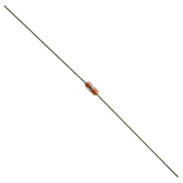
Infineon Technologies KTY13-7
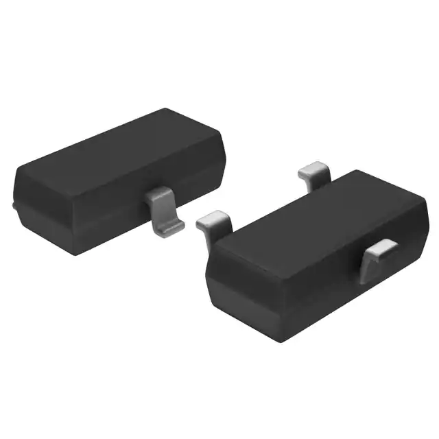
- Part No.:
- KTY13-7
- Manufacturer:
- Infineon Technologies
- Category:
- PTC Thermistors
- Package:
- TO-236-3, SC-59, SOT-23-3
- Datasheet:
-
 KTY13-7.pdf
- Description:
- SENSOR PTC 2.03KOHM 3% SOT23-3
- Quantity:
- Payment:

- Shipping:

Inventory:2,241
Please send an inquiry. Send us your inquiry, and we will respond immediately.
Product details
Overview
KTY13-7 from Infineon Technologies is a silicon-based positive temperature coefficient (PTC) temperature sensor in SOT-23 package, designed for analog temperature sensing in automotive and industrial control circuits. It exhibits R25 = 2010 Ω (min) / 2050 Ω (max) at 25 °C, operates from −50 °C to +150 °C, and delivers linearized resistance output with ±1% or ±3% tolerance options - used in motor winding temperature monitoring and HVAC refrigerant line sensing.
For engineers reviewing the KTY13-7 datasheet, KTY13-7 pinout, KTY13-7 application, or KTY13-7 equivalent, this page provides verified package mapping, thermal time constant (τair = 7 s), resistance vs. temperature coefficients (α = 7.88×10⁻³ K−1, β = 1.937×10⁻⁵ K−2), and direct substitution guidance for SOT-23 PTC thermistors in closed-loop thermal protection systems.
Technical Context
The KTY13-7 implements a planar n-conducting silicon crystal element whose resistance follows a second-order polynomial function RT = R25 × [1 + α·ΔT + β·(ΔT)2], valid from −30 °C to +130 °C. Its temperature factor kT = RT/R25 ranges from 0.506 at −50 °C to 2.274 at +150 °C.
It requires 1 mA operating current (Iop) for specified resistance accuracy, supports polarity-independent connection due to symmetrical two-terminal construction, and achieves τair = 7 s and τoil = 1 s thermal response - enabling fast detection of overtemperature events in compact motor housings and power electronics heatsinks.
Key Specifications
| Parameter | Value and Actual Design Meaning |
|---|---|
| R25 min/max | 2010 Ω / 2050 Ω at 25 °C - defines baseline resistance for calibration and analog-to-temperature conversion scaling |
| Temp range | −50 °C to +150 °C - supports under-hood automotive and industrial motor drive thermal monitoring |
| Thermal τair | 7 s - enables rapid detection of winding temperature rise during motor startup or overload |
| Temp coefficient α | 7.88×10⁻³ K−1 - primary linear term for resistance vs. temperature approximation |
| Temp coefficient β | 1.937×10⁻⁵ K−2 - quadratic correction term ensuring ±0.5 °C accuracy across full range |
| Max Iop | 5 mA - limits self-heating error to <0.1 °C at 1 mA bias, preserving measurement fidelity |
Pinout & Package
SOT-23 surface-mount package with symmetrical two-terminal construction; no polarity requirement. Dimensions: 2.9 mm × 1.3 mm × 1.0 mm (L × W × H); thermal pad not electrically connected.
| Pin/Terminal | Circuit Role | Design Meaning |
|---|---|---|
| Terminal 1 | Anode / Input | Connects to bias voltage or current source; interchangeable with Terminal 2 due to symmetrical design |
| Terminal 2 | Cathode / Output | Provides resistance-varying return path; same electrical function as Terminal 1 - bidirectional operation |
Key Features
| Feature | Design Value |
|---|---|
| Positive temperature coefficient (PTC) | Monotonic resistance increase with temperature - simplifies analog interface and eliminates sign ambiguity in signal conditioning |
| Linearized output curve | Second-order polynomial model (α, β coefficients provided) enables software compensation to ±0.5 °C without lookup tables |
| Polarity independence | Symmetrical two-terminal structure eliminates orientation errors during automated SMT placement and reduces BOM variants |
| Long-term stability | Drift <0.1% per 1000 hours at 125 °C - ensures calibration integrity in sealed motor windings over 10+ year service life |
Applications
| Motor Winding Protection | HVAC Refrigerant Line Monitoring |
|---|---|
Use Scenario: Embedded inside stator windings of BLDC motors to detect thermal runaway during stall or overload conditions. IC Role / Device Role / Timing Role: Analog temperature transducer providing resistance feedback to MCU ADC for real-time thermal derating. Use Value: τair = 7 s enables detection of 20 °C rise within 15 s - sufficient to trigger shutdown before insulation failure. | Use Scenario: Mounted on copper tubing downstream of expansion valve in automotive climate control systems. IC Role / Device Role / Timing Role: Two-terminal PTC resistor interfaced with simple voltage divider and comparator for freeze-protection cutoff. Use Value: R25 = 2010–2050 Ω allows precise 1 mA bias with <10 mW dissipation - avoids refrigerant boiling point shift. |
| Industrial Power Supply Thermal Sensing | Automotive Battery Junction Box Monitoring |
Use Scenario: Surface-mounted on heatsink near IGBT modules in servo drive inverters to track junction temperature indirectly. IC Role / Device Role / Timing Role: Passive resistance sensor feeding into isolated analog front-end for thermal foldback control loop. Use Value: −50 °C to +150 °C range covers cold-start to sustained overload conditions without sensor saturation. | Use Scenario: Integrated into high-current busbar assembly of 12 V battery distribution unit to monitor hotspot formation. IC Role / Device Role / Timing Role: SOT-23 footprint enables direct soldering onto copper busbar with minimal thermal mass penalty. Use Value: τoil = 1 s (in thermal compound) ensures sub-second response to localized resistive heating at bolted joints. |
Equivalent & Alternatives
The following parts are listed as comparable options for similar PTC temperature sensing applications.
| Alternative Part | Technical Difference | Application Difference | Selection Advice |
|---|---|---|---|
| KTY13-6 | R25 = 1980–2020 Ω; identical package, α/β coefficients, and thermal time constants | Same use cases but calibrated for lower baseline resistance - requires ADC gain adjustment | Select when existing system design uses 2.0 kΩ reference point and tighter R25 spread is needed |
| KTY23-7 | R25 = 1005–1025 Ω; same SOT-23 package and temperature range, but half the nominal resistance | Optimized for low-voltage bias (e.g., 3.3 V systems with 1 mA current limit); reduced self-heating at same power | Choose for battery-powered or low-power designs where 1 kΩ range improves SNR in 10-bit ADC implementations |
Compared with KTY13-6 and KTY23-7, the KTY13-7 offers the highest R25 in the KTY13-x series, delivering superior noise immunity in noisy motor drive environments while maintaining identical thermal dynamics and calibration structure.
Availability
KTY13-7 is available at Aetrix Electronics and suitable for motor winding protection, HVAC refrigerant line monitoring, industrial power supply thermal sensing, and automotive battery junction box monitoring requiring stable component supply across extended temperature ranges and long product lifecycles.
Supply support for KTY13-7 includes scheduled delivery planning, volume procurement assistance, BOM continuity management, traceable sourcing, and lifecycle availability coordination for OEM customers, industrial embedded developers, connected-device designers, and electronics production programs.
Manufacturer
Infineon Technologies is a German semiconductor manufacturer specializing in power management, sensor, and automotive ICs, with global manufacturing and quality certification to AEC-Q200 and ISO/TS 16949 standards.
The KTY-series is part of Infineon's analog temperature sensor product line, engineered specifically for high-reliability thermal monitoring in harsh environments where silicon PTC stability outperforms NTC thermistors and RTDs.
FAQ
What is the maximum allowable operating current for KTY13-7?
The absolute maximum operating current is 5 mA at TA ≤ 25 °C. Operation at 1 mA is recommended to limit self-heating error to <0.1 °C. Peak current up to 7 mA is permitted for ≤10 ms pulses, such as during diagnostic sampling, provided supply leads include >10 nF decoupling to suppress induced voltage spikes.
Can KTY13-7 be used in a Wheatstone bridge configuration?
Yes - its symmetrical two-terminal construction and tight R25 tolerance (±1% or ±3%) make it suitable as one arm of a balanced bridge. When paired with a matched fixed resistor, it delivers ratiometric output that rejects supply voltage variation, ideal for low-cost microcontroller-based temperature readouts without precision voltage references.
How is temperature calculated from KTY13-7 resistance measurements?
Temperature is derived using the second-order equation TA = [−α + √(α² − 4β + 4β·kT)] / (2β), where kT = RT/R25. Coefficients α = 7.88×10⁻³ K−1 and β = 1.937×10⁻⁵ K−2 are factory-characterized and valid from −30 °C to +130 °C, enabling software compensation with <0.5 °C error.
Is KTY13-7 compliant with automotive qualification standards?
Yes - KTY13-7 is qualified per AEC-Q200 Rev D for passive components, including stress testing for temperature cycling (−40 °C to +125 °C, 1000 cycles), humidity bias (85 °C/85% RH, 1000 h), and mechanical shock (1500 g). Its SOT-23 package meets reflow profile requirements for lead-free assembly in automotive ECUs and power modules.
KTY13-7 Specifications
- Product attributes
- Attribute value
- Manufacturer:
- Infineon Technologies
- Series:
- -
- Package/Case:
- TO-236-3, SC-59, SOT-23-3
- Packaging:
- Tape & Reel (TR)
- Product Status:
- Obsolete
- Resistance @ 25°C:
- 2.03 kOhms
- Resistance Tolerance:
- ±3%
- Operating Temperature:
- -50°C ~ 150°C
- Power - Max:
- -
- Mounting Type:
- Surface Mount
- Grade:
- -
- Qualification:
- -
- Supplier Device Package:
- SOT-23-3
KTY13-7 FAQ
1.How can I place an order for KTY13-7 through Aetrix?
Please submit a Request for Quotation (RFQ) for KTY13-7 on Aetrix. Our sales agent will provide a competitive quotation and guide you through the order confirmation once you accept the terms.
2.Are the price and stock information for KTY13-7 reliable?
The price and inventory of KTY13-7 are updated periodically and may fluctuate due to market conditions. Stock and pricing data are typically refreshed every 24 hours. Quotation validity for KTY13-7 is usually 5 days.
3.What payment methods are accepted for KTY13-7?
We accept Wire Transfer, PayPal, Credit Card, Western Union, MoneyGram, and Escrow for KTY13-7 transactions.
Note: Certain payment methods may incur a processing fee.
4.How is shipping managed for KTY13-7?
KTY13-7 orders can be shipped via leading logistics carriers, including DHL, UPS, FedEx, TNT, or Registered Mail.
Once your KTY13-7 order is processed, you will receive an email with the shipment details and tracking number.
Note: Tracking information may take up to 24 hours to appear. Express delivery typically takes 3–5 business days.
5.How can I obtain technical support or documentation for KTY13-7?
For technical support, including KTY13-7 datasheets, pinout diagrams, or application guidance, please contact our engineering support team. They can provide detailed documentation and assistance for your KTY13-7 requirements.
6.How does Aetrix verify that KTY13-7 is sourced from the original manufacturer or authorized distributors?
All KTY13-7 products on Aetrix are procured from qualified distributors and authorized channels. Our dedicated quality assurance team conducts strict verification, including traceability checks and, if necessary, third-party testing. This ensures that KTY13-7 meets industry standards.
7.What is the process for return or replacement of KTY13-7?
All KTY13-7 units undergo pre-shipment inspection (PSI). If there is an issue with KTY13-7, returns or replacements are accepted under the following conditions:
1.Quantity discrepancies, incorrect items, or visible external defects (such as breakage or corrosion), acknowledged by Aetrix.
2.The issue is reported within 90 days of delivery.
3.The KTY13-7 part is unused and in its original packaging.
Return procedure for KTY13-7:
1.Submit a request within 90 days.
2.Obtain a Return Material Authorization (RMA) from Aetrix.
KTY13-7 Tags
.jpg)
-
B59421A0075A062
EPCOS - TDK Electronics
-
B59641A0105A062
EPCOS - TDK Electronics

-
B59721A0100A062
EPCOS - TDK Electronics
-
B59701A0100A062
EPCOS - TDK Electronics
-
TFPT0603L1001FM
Vishay Dale
.jpg)
-
TFPT0805L1000FV
Vishay Dale
-
TFPT0603L1001FV
Vishay Dale
.jpg)
-
TFPT1206L1002FV
Vishay Dale

-
B59052D1090A040
EPCOS - TDK Electronics
-
102PS1G
Littelfuse Inc.
-
B59100M1100A070
EPCOS - TDK Electronics
-
STS110003CHIP
Cantherm
Tech Hub

Jumper cables guide covering safe connection order, red and black clamp placement, final ground connection, cable gauge, length, clamp quality, copper vs CCA cables, jump starter comparison and battery…

LDO regulator guide covering low dropout voltage, power dissipation, thermal design, PSRR, output noise, capacitor stability, adjustable LDO circuits, LDO vs buck converter and datasheet selection chec…

Conditional Access Module guide covering CAM meaning, CI/CI+ interface, smart card authorization, DVB security workflow, TV and set-top box compatibility, internal electronics, ESD protection, connecto…

Guide to electronic component obsolescence covering EOL risk, PCN/PDN notices, last-time buy planning, replacement options, form-fit-function validation, counterfeit risk and BOM lifecycle management.

18650 battery guide covering lithium-ion cell basics, 3.6V/3.7V voltage, 4.2V charging, mAh and Wh capacity, protected cells, chargers, BMS, series-parallel packs, holders, welding and sourcing checks.…

Hall effect sensor guide covering working principle, linear and digital sensors, Arduino circuits, current sensing, speed detection, automotive applications, A3144 examples, signal filtering and datash…

Product Change Notification guide for electronic components, covering PCN meaning, PCN vs PDN/EOL, common change types, risk levels, form-fit-function review, engineering validation, BOM control, LTB/L…

A practical guide to blend door actuators, covering HVAC function, symptoms, location, AC and heater issues, reset and calibration, replacement cost, electrical diagnosis, compatibility checks, and rep…

Engineering guide to Raspberry Pi alternatives, covering chip-level differences, Orange Pi, ROCK, Jetson, Banana Pi, NanoPi, Compute Module, Pico, GPIO, camera, HAT compatibility, and replacement risks…

Engineering guide to dynamic load response testing for high-current buck converters, covering load step setup, slew rate, Vcore undershoot, overshoot, recovery time, probe location, output capacitors a…


