
 My Inquiry
 My Account


NXP Semiconductors KTY81/110,112
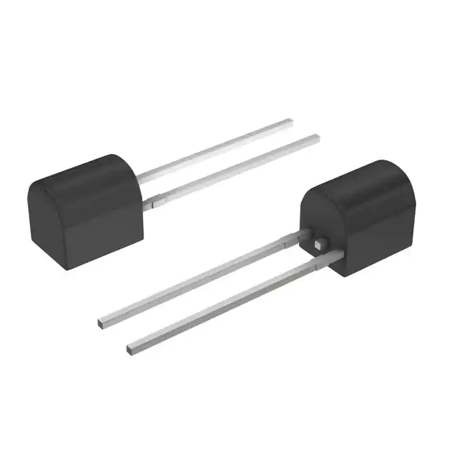
- Part No.:
- KTY81/110,112
- Manufacturer:
- NXP Semiconductors
- Category:
- PTC Thermistors
- Package:
- TO-226-2, TO-92-2 (TO-226AC)
- Datasheet:
-
 KTY81/110,112.pdf
- Description:
- SENSOR PTC 1KOHM PBCYT2
- Quantity:
- Payment:

- Shipping:

Inventory:4,688
Please send an inquiry. Send us your inquiry, and we will respond immediately.
Product details
Overview
KTY81/110,112 from NXP Semiconductors is a silicon-based analog temperature sensor with positive temperature coefficient (PTC) resistance behavior, designed for precision measurement and closed-loop control in industrial and automotive thermal monitoring systems. It delivers R25 = 990–1010 Ω at 25 °C, ±1.27 K max temperature error over −55 to +150 °C, and 0.79 %/K nominal temperature coefficient.
For engineers reviewing the KTY81/110,112 datasheet, KTY81/110,112 pinout, KTY81/110,112 application, or KTY81/110,112 equivalent, this page provides verified package mapping, resistance-vs-temperature tables, thermal time constant data (3 s in flowing liquid), continuous current limits (2 mA @ 150 °C), and validated alternatives for thermal sensing circuit design.
Technical Context
The KTY81/110,112 operates as a two-terminal passive resistive element whose resistance increases linearly with ambient temperature-enabling direct voltage-divider interfacing with ADCs or op-amp conditioning circuits. Its PTC behavior ensures fail-safe operation: rising resistance under overtemperature conditions reduces self-heating and prevents runaway failure modes.
It exhibits virtually linear R–T characteristics across −55 °C to +150 °C, with R100/R25 = 1.676–1.716 and R−55/R25 = 0.480–0.500. Thermal time constants are specified as 3 s (flowing liquid), 5 s (still liquid), and 30 s (still air), defining dynamic response suitability for real-time thermal feedback loops.
Key Specifications
| Parameter | Value and Actual Design Meaning |
|---|---|
| R25 | 990–1010 Ω at 25 °C; defines baseline resistance for calibration and divider ratio selection |
| Temperature Coefficient | 0.79 %/K typical; enables predictable resistance change per degree for linearized readout |
| R100/R25 | 1.676–1.716; quantifies resistance increase at 100 °C vs. 25 °C for high-temp accuracy validation |
| Max Temp Error | ±1.27 K at 25 °C; sets absolute accuracy bound for system-level thermal compensation |
| Thermal Time Constant | 3 s in flowing liquid; determines minimum sampling interval for transient thermal tracking |
| Continuous Current Limit | 2 mA at 150 °C; defines maximum bias current to avoid self-heating-induced drift |
| Operating Range | −55 °C to +150 °C; supports under-hood, motor winding, and industrial process monitoring |
Pinout & Package
Encapsulated in the SOD70 plastic near-cylindrical single-ended package with 2 in-line leads, the KTY81/110,112 has no polarity or orientation dependency. The device is mechanically symmetric and electrically bidirectional.
| Pin/Terminal | Circuit Role | Design Meaning |
|---|---|---|
| 1 | Electrical contact | Interchangeable terminal for series connection into voltage divider or current-sense path |
| 2 | Electrical contact | Interchangeable terminal; no functional distinction from Pin 1; bidirectional conduction |
Key Features
| Feature | Design Value |
|---|---|
| Positive Temperature Coefficient (PTC) | Fail-safe behavior: resistance rises with temperature, inherently limiting current and preventing thermal runaway |
| Virtually Linear R–T Curve | Enables direct analog-to-digital conversion without complex polynomial compensation in many applications |
| Long-Term Stability | ≤1.6 Ω resistance drift after 10,000 h at 150 °C (KTY81/1 series); critical for maintenance-free industrial deployments |
| ESD-Sensitive Handling | Requires ESD-safe transport and PCB handling per IEC 61000-4-2; avoids parametric shift during assembly |
| Low Self-Heating Error | Specified at 1 mA operating current; keeps ΔT < 0.1 K in still air, preserving measurement fidelity |
Applications
| Motor Winding Monitoring | Automotive Cabin Climate Control |
|---|---|
Use Scenario: Real-time temperature sensing of stator windings in BLDC motors to prevent insulation breakdown. IC Role / Device Role / Timing Role: Passive resistive sensor providing analog R–T signal to microcontroller ADC input. Use Value: ±1.27 K accuracy at 25 °C and 3 s thermal response in oil-cooled environments enable predictive thermal shutdown before damage occurs. |
Use Scenario: Ambient cabin air temperature feedback for HVAC blower speed and blend door actuation. IC Role / Device Role / Timing Role: Two-terminal analog temperature transducer interfaced via simple voltage divider. Use Value: R25 = 990–1010 Ω and 0.79 %/K TC allow stable 12-bit ADC resolution down to 0.25 °C LSB without software linearization. |
| Industrial Oven Temperature Profiling | Power Supply Thermal Foldback |
Use Scenario: Multi-point thermal profiling inside convection ovens for food processing and curing cycles. IC Role / Device Role / Timing Role: Discrete PTC sensor mounted on thermally conductive substrate for uniform heat transfer. Use Value: −55 °C to +150 °C range and 5 s thermal time constant in still liquid match oven ramp/soak profiles with minimal lag. |
Use Scenario: Overtemperature detection in DC–DC converter output stage to reduce load current before MOSFET failure. IC Role / Device Role / Timing Role: Fail-safe analog sensor in series with bias resistor, triggering comparator threshold. Use Value: PTC behavior ensures monotonic resistance rise with junction temperature, enabling reliable foldback without active circuitry. |
Equivalent & Alternatives
The following parts are listed as comparable options for similar silicon PTC temperature sensing applications.
| Alternative Part | Technical Difference | Application Difference | Selection Advice |
|---|---|---|---|
| TSI301-100 | R25 = 1000 Ω ±1 %, TC = 0.78 %/K, SOT-23 package, 3-pin configuration | Requires PCB layout revision due to surface-mount 3-pin footprint and different biasing topology | Preferred when space-constrained PCBs demand SMT placement and tighter initial tolerance is required |
| KTY83-110 | R25 = 950–1050 Ω, wider tolerance, TO-92 package, higher thermal mass (τth = 15 s in air) | Slower response limits use in fast-transient thermal control; larger through-hole footprint | Selected where legacy TO-92 compatibility or higher power dissipation margin (>5 mW) is prioritized over speed |
Compared with KTY81/110,112, TSI301-100 offers tighter R25 tolerance but demands redesign for SMT integration, while KTY83-110 trades speed and precision for mechanical robustness and legacy compatibility-making KTY81/110,112 optimal for new designs requiring balance of accuracy, speed, and through-hole manufacturability.
Availability
KTY81/110,112 is available at Aetrix Electronics and suitable for motor protection, automotive climate control, industrial oven profiling, and power supply thermal foldback requiring stable component supply across extended temperature ranges and long product lifecycles.
Supply support for KTY81/110,112 includes scheduled delivery planning, volume procurement assistance, BOM continuity management, traceable sourcing, and lifecycle availability coordination for OEM customers, industrial embedded developers, connected-device designers, and electronics production programs.
Manufacturer
NXP Semiconductors is a global semiconductor company headquartered in Eindhoven, Netherlands, specializing in secure connectivity solutions for automotive, industrial, and IoT applications.
The KTY81 series was developed by NXP to deliver high-stability, linear PTC silicon temperature sensors for cost-sensitive yet reliability-critical thermal monitoring in harsh environments-replacing thermistors where long-term drift and linearity are design constraints.
FAQ
What is the recommended operating current for KTY81/110,112 to minimize self-heating error?
The KTY81/110,112 datasheet specifies Isen(cont) = 1 mA as the recommended operating current for temperatures above 100 °C to keep temperature error low. At this current, self-heating remains below 0.1 K in still air, preserving measurement accuracy. Exceeding 2 mA at 150 °C violates limiting values and risks long-term drift. Always verify bias network power dissipation using R25 = 990–1010 Ω when designing the voltage divider for KTY81/110,112.
Does KTY81/110,112 have polarity or directional mounting requirements?
No, KTY81/110,112 is a two-terminal passive resistive device with no polarity. Pins 1 and 2 are electrically identical and interchangeable-mounting orientation does not affect function. The SOD70 package is mechanically symmetric, and the sensor operates identically regardless of current direction. This simplifies PCB layout and eliminates risk of reverse installation during assembly of KTY81/110,112.
How does the temperature coefficient of KTY81/110,112 vary across its operating range?
The temperature coefficient of KTY81/110,112 decreases with rising temperature: it is 0.79 %/K at 25 °C, 0.63 %/K at 100 °C, and 0.35 %/K at 150 °C. This non-constant TC is documented in Table 7 of the datasheet and results in a slightly sub-linear R–T curve. For high-accuracy applications above 100 °C, interpolation using the published resistance tables-not a fixed TC-is required to achieve ±1.27 K error bounds for KTY81/110,112.
Can KTY81/110,112 be used in liquid immersion environments?
Yes, KTY81/110,112 is qualified for use in liquid immersion, with thermal time constant specified as 5 s in still liquid and 3 s in flowing liquid. Its SOD70 plastic encapsulation provides moisture resistance suitable for coolant, oil, and non-corrosive aqueous media. However, prolonged exposure to aggressive solvents or high-pressure steam is not supported. All resistance and error specifications in the datasheet-including R25 = 990–1010 Ω-are defined under liquid-immersion test conditions for KTY81/110,112.
What is the maximum allowable continuous current for KTY81/110,112 at 125 °C ambient?
At Tamb = 125 °C, the maximum continuous sensor current for KTY81/110,112 is 3.5 mA, interpolated from the limiting values table (2 mA at 150 °C; 10 mA at 25 °C). Operation above this value risks accelerated resistance drift and violates the Absolute Maximum Rating System per IEC 60134. For reliable 125 °C operation, maintain Isen(cont) ≤ 3.5 mA and confirm power dissipation stays below 3.5 mW using worst-case R25 = 1010 Ω when designing the interface for KTY81/110,112.
KTY81/110,112 Specifications
- Product attributes
- Attribute value
- Manufacturer:
- NXP Semiconductors
- Series:
- KTY81
- Package/Case:
- TO-226-2, TO-92-2 (TO-226AC)
- Packaging:
- Bulk
- Product Status:
- Obsolete
- Resistance @ 25°C:
- 1 kOhms
- Resistance Tolerance:
- -
- Operating Temperature:
- -55°C ~ 150°C
- Power - Max:
- -
- Mounting Type:
- Through Hole
- Grade:
- -
- Qualification:
- -
- Supplier Device Package:
- PBCYT2
KTY81/110,112 FAQ
1.How can I place an order for KTY81/110,112 through Aetrix?
Please submit a Request for Quotation (RFQ) for KTY81/110,112 on Aetrix. Our sales agent will provide a competitive quotation and guide you through the order confirmation once you accept the terms.
2.Are the price and stock information for KTY81/110,112 reliable?
The price and inventory of KTY81/110,112 are updated periodically and may fluctuate due to market conditions. Stock and pricing data are typically refreshed every 24 hours. Quotation validity for KTY81/110,112 is usually 5 days.
3.What payment methods are accepted for KTY81/110,112?
We accept Wire Transfer, PayPal, Credit Card, Western Union, MoneyGram, and Escrow for KTY81/110,112 transactions.
Note: Certain payment methods may incur a processing fee.
4.How is shipping managed for KTY81/110,112?
KTY81/110,112 orders can be shipped via leading logistics carriers, including DHL, UPS, FedEx, TNT, or Registered Mail.
Once your KTY81/110,112 order is processed, you will receive an email with the shipment details and tracking number.
Note: Tracking information may take up to 24 hours to appear. Express delivery typically takes 3–5 business days.
5.How can I obtain technical support or documentation for KTY81/110,112?
For technical support, including KTY81/110,112 datasheets, pinout diagrams, or application guidance, please contact our engineering support team. They can provide detailed documentation and assistance for your KTY81/110,112 requirements.
6.How does Aetrix verify that KTY81/110,112 is sourced from the original manufacturer or authorized distributors?
All KTY81/110,112 products on Aetrix are procured from qualified distributors and authorized channels. Our dedicated quality assurance team conducts strict verification, including traceability checks and, if necessary, third-party testing. This ensures that KTY81/110,112 meets industry standards.
7.What is the process for return or replacement of KTY81/110,112?
All KTY81/110,112 units undergo pre-shipment inspection (PSI). If there is an issue with KTY81/110,112, returns or replacements are accepted under the following conditions:
1.Quantity discrepancies, incorrect items, or visible external defects (such as breakage or corrosion), acknowledged by Aetrix.
2.The issue is reported within 90 days of delivery.
3.The KTY81/110,112 part is unused and in its original packaging.
Return procedure for KTY81/110,112:
1.Submit a request within 90 days.
2.Obtain a Return Material Authorization (RMA) from Aetrix.
KTY81/110,112 Tags
.jpg)
-
B59421A0075A062
EPCOS - TDK Electronics
-
B59641A0105A062
EPCOS - TDK Electronics

-
B59721A0100A062
EPCOS - TDK Electronics
-
B59701A0100A062
EPCOS - TDK Electronics
-
TFPT0603L1001FM
Vishay Dale
.jpg)
-
TFPT0805L1000FV
Vishay Dale
-
TFPT0603L1001FV
Vishay Dale
.jpg)
-
TFPT1206L1002FV
Vishay Dale
-
B59052D1090A040
EPCOS - TDK Electronics
-
102PS1G
Littelfuse Inc.
-
B59100M1100A070
EPCOS - TDK Electronics
-
STS110003CHIP
Cantherm
Tech Hub

A practical engineering guide to 3.3V and 5V logic compatibility, input thresholds, resistor dividers, translator ICs, MOSFET level shifting, I2C pull-ups, timing limits and power-sequencing risks.

The 74HC595 uses push-pull logic outputs, while the TPIC6B595 uses 50 V open-drain DMOS sinks for higher-power loads. This guide compares timing, current limits, 3.3 V interfacing, load wiring, thermal…

The 74HC595 converts serial data into eight stable parallel outputs. This guide covers pin functions, shift and storage timing, OE and MR behavior, drive-current limits, cascading, voltage compatibilit…

A technical comparison of level-sensitive latches and edge-triggered flip-flops, covering timing windows, setup and hold limits, master–slave operation, time borrowing, race-through, HDL inference and…

A D latch stores one bit while Enable controls when data can pass. This reference covers gate-level operation, truth tables, transparency, setup and hold timing, LE versus OE, common ICs and practical …

An SR latch stores one bit through cross-coupled feedback. This engineering reference covers NOR and NAND implementations, truth tables, forbidden-state recovery, gated operation, switch debouncing, fa…

Latch circuits retain one bit through feedback. This technical reference covers SR and D latches, truth tables, transparency, timing limits, latch-versus-flip-flop behavior, applications and common log…

An engineering guide to LED driver operation, constant-current and constant-voltage outputs, linear and switching topologies, dimming, IC selection, calculations, replacement compatibility, and fault c…

Operational amplifier guide covering op amp basics, feedback, ideal vs real op amps, common configurations, buffer circuits, offset, bias current, gain-bandwidth, slew rate, rail-to-rail limits and sel…

Jumper cables guide covering safe connection order, red and black clamp placement, final ground connection, cable gauge, length, clamp quality, copper vs CCA cables, jump starter comparison and battery…


