
 My Inquiry
 My Account


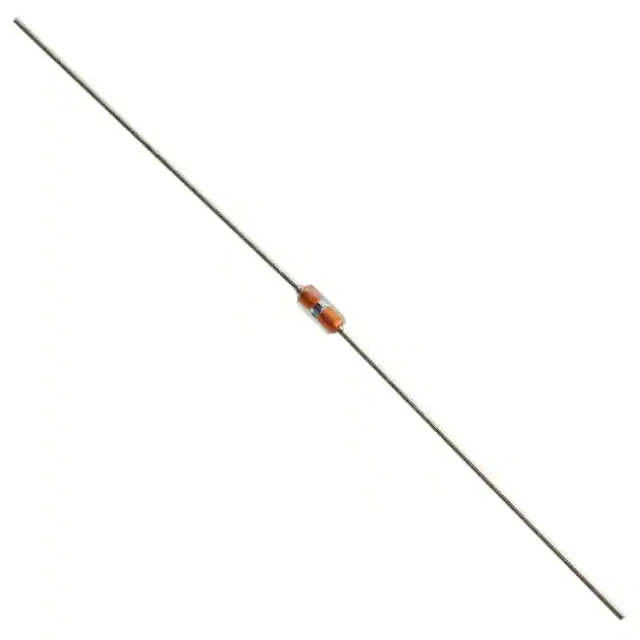
NXP Semiconductors KTY81/210,116
- Part No.:
- KTY81/210,116
- Manufacturer:
- NXP Semiconductors
- Category:
- PTC Thermistors
- Package:
- TO-226-2, TO-92-2 (TO-226AC)
- Datasheet:
-
 KTY81/210,116.pdf
- Description:
- SENSOR PTC 2KOHM PBCYT2
- Quantity:
- Payment:

- Shipping:

Inventory:1,955
Please send an inquiry. Send us your inquiry, and we will respond immediately.
Product details
Overview
KTY81/210,116 from NXP Semiconductors is a silicon-based positive temperature coefficient (PTC) temperature sensor in SOD70 plastic package, with nominal resistance of 2000 Ω at 25 °C, ±0.79 %/K temperature coefficient, and operating range from −55 °C to +150 °C. It delivers stable resistance-vs-temperature linearity for HVAC airflow monitoring, motor winding thermal protection, and industrial oven temperature feedback.
For engineers reviewing the KTY81/210,116 datasheet, KTY81/210,116 pinout, KTY81/210,116 application, or KTY81/210,116 equivalent, this page provides verified resistance values across −55 °C to 150 °C, thermal time constants in air/liquid, long-term drift specification, fail-safe PTC behavior, and direct alternative part comparisons for thermal sensing circuit redesign.
Technical Context
The KTY81/210,116 operates as a two-terminal passive resistive element requiring external bias current (recommended 1 mA) to generate voltage proportional to temperature. Its PTC response ensures monotonic, predictable resistance increase with rising ambient temperature - eliminating ambiguity in fault detection scenarios.
Resistance variation follows a well-characterized curve with R100/R25 = 1.696 and R−55/R25 = 0.490, enabling accurate linearization via lookup tables or polynomial compensation. Thermal time constant is 30 s in still air and 3 s in flowing liquid, defining dynamic response limits for closed-loop control timing.
Key Specifications
| Parameter | Value and Actual Design Meaning |
|---|---|
| R25 | 1980–2020 Ω at 25 °C; defines baseline scaling for analog-to-temperature conversion circuits |
| Temperature Coefficient | 0.79 %/K typical; enables predictable resistance change per degree for calibration-free designs |
| R100/R25 | 1.676–1.716; quantifies resistance ratio between 100 °C and 25 °C for high-temp accuracy validation |
| Operating Range | −55 °C to +150 °C; supports under-hood automotive, industrial motor, and power supply thermal monitoring |
| Max Continuous Current | 10 mA at 25 °C; sets upper limit for excitation current to avoid self-heating error & drift |
| Thermal Time Constant | 30 s in still air; determines minimum sampling interval for transient temperature tracking |
| Long-Term Drift | ≤3.2 Ω after 10,000 h at 150 °C; guarantees stability in continuous high-temp operation |
Pinout & Package
Package: SOD70 - near-cylindrical plastic case with two inline leads, 2.54 mm lead pitch (bulk), 5.08 mm spread lead pitch (reel), body dimensions 4.4–4.8 mm wide × 5.0–5.2 mm high × 3.6–4.2 mm thick.
| Pin/Terminal | Circuit Role | Design Meaning |
|---|---|---|
| 1 | Electrical contact | Unpolarized terminal; connects to bias current source or voltage divider node |
| 2 | Electrical contact | Unpolarized terminal; completes current path; no functional distinction from Pin 1 |
Key Features
| Feature | Design Value |
|---|---|
| Positive Temperature Coefficient (PTC) | Fail-safe behavior: resistance increases with temperature, preventing undetected overtemperature failure |
| Virtually Linear Characteristics | ±1.27 K max temperature error at 25 °C enables simple 2-point calibration for <±2 K system accuracy |
| Long-Term Stability | Drift ≤3.2 Ω after 10,000 h at 150 °C supports 10+ year reliability in sealed industrial enclosures |
| ESD-Sensitive Construction | Requires handling per IEC 61000-4-2 Level 2; avoids gate oxide damage during PCB assembly |
| Wide Operating Range | −55 °C to +150 °C ambient rating allows direct mounting on heatsinks, motors, and power semiconductors |
Applications
| Motor Winding Protection | HVAC Airflow Sensing |
|---|---|
Use Scenario: Embedded inside stator windings of industrial AC motors to detect thermal overload before insulation breakdown. IC Role / Device Role / Timing Role: Passive resistive temperature transducer; no timing role; provides analog resistance signal to comparator or ADC. Use Value: PTC behavior ensures resistance rises predictably with winding temperature, triggering shutdown before irreversible damage occurs. | Use Scenario: Mounted in ductwork upstream of heat exchangers to monitor supply air temperature for PID-controlled fan speed modulation. IC Role / Device Role / Timing Role: Analog temperature sensing element; interfaces with microcontroller ADC via simple voltage divider. Use Value: 30 s thermal time constant in air matches HVAC thermal mass dynamics, avoiding false alarms from transient airflow pulses. |
| Oven Temperature Feedback | Power Supply Thermal Monitoring |
Use Scenario: Surface-mounted on heating element brackets in commercial convection ovens to regulate setpoint accuracy within ±2 °C. IC Role / Device Role / Timing Role: Two-terminal analog sensor; no active circuitry; requires external 1 mA bias for linear response. Use Value: R100/R25 = 1.696 enables precise polynomial compensation to meet IEC 60519 Class B oven calibration requirements. | Use Scenario: Attached to MOSFET heatsink in telecom DC-DC converters to throttle output power before thermal shutdown. IC Role / Device Role / Timing Role: Fail-safe thermal sentinel; resistance increase directly correlates with junction temperature rise. Use Value: 150 °C max ambient rating allows direct placement on thermally coupled surfaces without derating. |
Equivalent & Alternatives
The following parts are listed as comparable options for similar silicon PTC temperature sensing applications.
| Alternative Part | Technical Difference | Application Difference | Selection Advice |
|---|---|---|---|
| KTY81/220 | Same SOD70 package; R25 = 1960–2040 Ω; identical TC and R100/R25 spec | No functional difference; used where tighter initial tolerance not required | Select when ±20 Ω R25 tolerance is acceptable versus KTY81/210,116's ±20 Ω window centered at 2000 Ω |
| TSI301-2000 | Different SOT-23-3 package; 2000 Ω ±1 % at 25 °C; integrated ESD protection; higher cost | Requires PCB layout change; offers better initial accuracy but less rugged mechanical form factor | Choose only if 1 % R25 tolerance and surface-mount compatibility outweigh SOD70's axial-leaded robustness |
Compared with KTY81/210,116, KTY81/220 offers identical thermal performance with looser R25 bounds, while TSI301-2000 trades mechanical ruggedness for tighter tolerance and SMT fit - making KTY81/210,116 optimal for cost-sensitive, high-reliability axial-leaded thermal monitoring.
Availability
KTY81/210,116 is available at Aetrix Electronics and suitable for HVAC airflow sensing, motor winding protection, and oven temperature feedback requiring stable component supply across extended temperature ranges and multi-year production cycles.
Supply support for KTY81/210,116 includes scheduled delivery planning, volume procurement assistance, BOM continuity management, traceable sourcing, and lifecycle availability coordination for OEM customers, industrial embedded developers, connected-device designers, and electronics production programs.
Manufacturer
NXP Semiconductors is a global semiconductor company headquartered in Eindhoven, Netherlands, specializing in secure connectivity solutions for automotive, industrial, and IoT applications.
The KTY81 series was designed by NXP as low-cost, high-stability silicon PTC sensors targeting thermal protection and measurement in harsh environments where ceramic or thermistor alternatives lack long-term drift performance.
FAQ
What is the recommended operating current for KTY81/210,116 to minimize self-heating error?
The recommended continuous operating current for KTY81/210,116 is 1 mA, as specified in the datasheet for all resistance and temperature error measurements. At this level, self-heating remains below 0.1 K in still air, preserving measurement accuracy. Exceeding 10 mA at 25 °C risks permanent drift; KTY81/210,116 must be biased within its absolute maximum ratings to maintain long-term stability.
Does KTY81/210,116 require polarity-aware connection in circuit?
No, KTY81/210,116 is a two-terminal passive resistor with no polarity; Pins 1 and 2 are electrically identical and interchangeable. The device functions identically regardless of orientation in a voltage divider or constant-current bias configuration. This simplifies PCB layout and eliminates risk of reverse installation - a key advantage over diode-based or IC temperature sensors.
How does the temperature coefficient of KTY81/210,116 compare to NTC thermistors in practical use?
KTY81/210,116 has a positive temperature coefficient of 0.79 %/K, meaning resistance increases predictably with temperature - unlike NTC thermistors whose resistance drops nonlinearly. This PTC behavior provides inherent fail-safe detection: open-circuit or wiring fault yields infinite resistance (interpreted as overtemperature), whereas NTC faults may mimic normal cold-state readings. KTY81/210,116 thus reduces system-level diagnostic complexity.
Can KTY81/210,116 be used in reflow soldering processes?
KTY81/210,116 is qualified for wave soldering and hand-soldering per its SOD70 package specifications, but is not rated for standard Pb-free reflow profiles (e.g., JEDEC J-STD-020). Peak temperatures above 260 °C risk internal bond degradation. For automated assembly, selective soldering or adhesive mounting followed by hand-soldering of leads is recommended to preserve KTY81/210,116's long-term drift performance and mechanical integrity.
What is the maximum expected temperature error of KTY81/210,116 at 100 °C?
At 100 °C, the maximum expected temperature error for KTY81/210,116 is ±3.46 K when operated at 1 mA, as documented in Table 10 of the NXP datasheet. This error includes contributions from resistance tolerance, nonlinearity, and thermal time constant effects. For applications requiring tighter accuracy, polynomial compensation using R100/R25 = 1.696 and R−55/R25 = 0.490 can reduce residual error to <±1 K across −20 °C to 120 °C.
KTY81/210,116 Specifications
- Product attributes
- Attribute value
- Manufacturer:
- NXP Semiconductors
- Series:
- KTY81
- Package/Case:
- TO-226-2, TO-92-2 (TO-226AC)
- Packaging:
- Tape & Reel (TR)
- Product Status:
- Obsolete
- Resistance @ 25°C:
- 2 kOhms
- Resistance Tolerance:
- -
- Operating Temperature:
- -55°C ~ 150°C
- Power - Max:
- -
- Mounting Type:
- Through Hole
- Grade:
- -
- Qualification:
- -
- Supplier Device Package:
- PBCYT2
KTY81/210,116 FAQ
1.How can I place an order for KTY81/210,116 through Aetrix?
Please submit a Request for Quotation (RFQ) for KTY81/210,116 on Aetrix. Our sales agent will provide a competitive quotation and guide you through the order confirmation once you accept the terms.
2.Are the price and stock information for KTY81/210,116 reliable?
The price and inventory of KTY81/210,116 are updated periodically and may fluctuate due to market conditions. Stock and pricing data are typically refreshed every 24 hours. Quotation validity for KTY81/210,116 is usually 5 days.
3.What payment methods are accepted for KTY81/210,116?
We accept Wire Transfer, PayPal, Credit Card, Western Union, MoneyGram, and Escrow for KTY81/210,116 transactions.
Note: Certain payment methods may incur a processing fee.
4.How is shipping managed for KTY81/210,116?
KTY81/210,116 orders can be shipped via leading logistics carriers, including DHL, UPS, FedEx, TNT, or Registered Mail.
Once your KTY81/210,116 order is processed, you will receive an email with the shipment details and tracking number.
Note: Tracking information may take up to 24 hours to appear. Express delivery typically takes 3–5 business days.
5.How can I obtain technical support or documentation for KTY81/210,116?
For technical support, including KTY81/210,116 datasheets, pinout diagrams, or application guidance, please contact our engineering support team. They can provide detailed documentation and assistance for your KTY81/210,116 requirements.
6.How does Aetrix verify that KTY81/210,116 is sourced from the original manufacturer or authorized distributors?
All KTY81/210,116 products on Aetrix are procured from qualified distributors and authorized channels. Our dedicated quality assurance team conducts strict verification, including traceability checks and, if necessary, third-party testing. This ensures that KTY81/210,116 meets industry standards.
7.What is the process for return or replacement of KTY81/210,116?
All KTY81/210,116 units undergo pre-shipment inspection (PSI). If there is an issue with KTY81/210,116, returns or replacements are accepted under the following conditions:
1.Quantity discrepancies, incorrect items, or visible external defects (such as breakage or corrosion), acknowledged by Aetrix.
2.The issue is reported within 90 days of delivery.
3.The KTY81/210,116 part is unused and in its original packaging.
Return procedure for KTY81/210,116:
1.Submit a request within 90 days.
2.Obtain a Return Material Authorization (RMA) from Aetrix.
KTY81/210,116 Tags
.jpg)
-
B59421A0075A062
EPCOS - TDK Electronics
-
B59641A0105A062
EPCOS - TDK Electronics

-
B59721A0100A062
EPCOS - TDK Electronics
-
B59701A0100A062
EPCOS - TDK Electronics
-
TFPT0603L1001FM
Vishay Dale
.jpg)
-
TFPT0805L1000FV
Vishay Dale
-
TFPT0603L1001FV
Vishay Dale
.jpg)
-
TFPT1206L1002FV
Vishay Dale
-
B59052D1090A040
EPCOS - TDK Electronics
-
102PS1G
Littelfuse Inc.
-
B59100M1100A070
EPCOS - TDK Electronics
-
STS110003CHIP
Cantherm
Tech Hub

A practical engineering guide to 3.3V and 5V logic compatibility, input thresholds, resistor dividers, translator ICs, MOSFET level shifting, I2C pull-ups, timing limits and power-sequencing risks.

The 74HC595 uses push-pull logic outputs, while the TPIC6B595 uses 50 V open-drain DMOS sinks for higher-power loads. This guide compares timing, current limits, 3.3 V interfacing, load wiring, thermal…

The 74HC595 converts serial data into eight stable parallel outputs. This guide covers pin functions, shift and storage timing, OE and MR behavior, drive-current limits, cascading, voltage compatibilit…

A technical comparison of level-sensitive latches and edge-triggered flip-flops, covering timing windows, setup and hold limits, master–slave operation, time borrowing, race-through, HDL inference and…

A D latch stores one bit while Enable controls when data can pass. This reference covers gate-level operation, truth tables, transparency, setup and hold timing, LE versus OE, common ICs and practical …

An SR latch stores one bit through cross-coupled feedback. This engineering reference covers NOR and NAND implementations, truth tables, forbidden-state recovery, gated operation, switch debouncing, fa…

Latch circuits retain one bit through feedback. This technical reference covers SR and D latches, truth tables, transparency, timing limits, latch-versus-flip-flop behavior, applications and common log…

An engineering guide to LED driver operation, constant-current and constant-voltage outputs, linear and switching topologies, dimming, IC selection, calculations, replacement compatibility, and fault c…

Operational amplifier guide covering op amp basics, feedback, ideal vs real op amps, common configurations, buffer circuits, offset, bias current, gain-bandwidth, slew rate, rail-to-rail limits and sel…

Jumper cables guide covering safe connection order, red and black clamp placement, final ground connection, cable gauge, length, clamp quality, copper vs CCA cables, jump starter comparison and battery…


